JVC DV-180 User manual

OPERATIONS MANUAL
for a
JVC DV-180
CONTROLLER
.
Prepared for: JVC Professional Products Company
1700 Valley Road
Wayne, NJ 07470
Document No. D0154
Date: 19 November 2003
Revision: A

Table of Contents
1. DESCRIPTION4
1.1 FUNCTIONAL DESCRIPTION .................................................................................................................................. 4
1.2 PHYSICAL DESCRIPTION ....................................................................................................................................... 4
2. DV-180 CONTROLLER SPECIFICATIONS: ................................................................................................... 5
3. INSTALLATION ................................................................................................................................................... 6
3.1 TOOLS AND EQUIPMENT REQUIRED:..................................................................................................................... 6
3.2 RS-422 CABLE INSTALLATION ............................................................................................................................. 6
3.3 CAMERA CONTROL CABLE .................................................................................................................................. 7
3.4 GROUND WIRE ..................................................................................................................................................... 7
3.5 POWER MODULE................................................................................................................................................... 7
3.6 POWER “ON” INDICATOR TEST ............................................................................................................................ 7
3.7 ANALOG CONTROL CALIBRATION ........................................................................................................................ 7
4. FRONT PANEL-CONTROLS AND INDICATORS.......................................................................................... 8
4.1 POWER SWITCH .................................................................................................................................................... 8
4.2 POWER INDICATOR ............................................................................................................................................... 8
4.3 PAGE SWITCH AND INDICATOR ............................................................................................................................. 9
4.4 PROGRAM SWITCH AND INDICATOR ..................................................................................................................... 9
4.5 CAMERA SELECT SWITCH AND INDICATOR .......................................................................................................... 9
4.6 AUXILIARY 1 SWITCH AND INDICATOR ................................................................................................................ 9
4.7 AUXILIARY 2 SWITCH AND INDICATOR .............................................................................................................. 10
4.8 PRESET SWITCHES AND INDICATORS .................................................................................................................. 10
4.9 ZOOM & FOCUS - SEESAWS CONTROLS.............................................................................................................. 10
4.10 JOYSTICK............................................................................................................................................................ 10
5. REAR PANEL-CONNECTORS AND SWITCHES......................................................................................... 11
5.1 COMPUTER CONTROL CONNECTOR .................................................................................................................... 11
5.2 CAMERA 1 - 4 CONNECTORS ............................................................................................................................ 11
5.3 GROUND SCREW ................................................................................................................................................ 11
5.4 DC JACK, POWER REQUIREMENTS .................................................................................................................... 11
5.5 REAR PANEL DIP SWITCHES .............................................................................................................................. 12
5.6 RS-422 CONNECTORS ........................................................................................................................................ 13
6DV-180 PC COMM.............................................................................................................................................. 14
7. OPERATION........................................................................................................................................................ 15
7.1 COMMUNICATION INTERFACE ............................................................................................................................ 15
7.2 POWER ON.......................................................................................................................................................... 15
JVC DV-180 PAN/TILT Operations Manual Doc #: D0154-A
2

7.3 MANUAL OPERATION ......................................................................................................................................... 15
7.4 PROGRAMMING A PRESET LOCATION ................................................................................................................. 15
7.5 TO GO TO A PRESET LOCATION:......................................................................................................................... 16
7.6 DV-180 PC COMM............................................................................................................................................. 16
7.7 TO REVERSE MANUAL CONTROL FUNCTIONS .................................................................................................... 16
7.8 TO SET THE SPEED RANGE ................................................................................................................................. 16
7.9 VIDEO RECORDER CONTROLS ............................................................................................................................ 17
7.10 AUTO FOCUS ...................................................................................................................................................... 17
7.11 MANUAL IRIS ..................................................................................................................................................... 17
7.12 AUTO IRIS........................................................................................................................................................... 17
7.13 COLOR BAR GENERATION .................................................................................................................................. 18
7.14 CABLE DRAWINGS.............................................................................................................................................. 18
8. TROUBLE SHOOTING...................................................................................................................................... 20
8.1 PAN & TILT ........................................................................................................................................................ 20
8.2 DV-180 PC COMM............................................................................................................................................. 20
8.3 TECHNICAL SUPPORT.......................................................................................................................................... 20
JVC DV-180 PAN/TILT Operations Manual Doc #: D0154-A
3

1. DESCRIPTION
1.1 FUNCTIONAL DESCRIPTION
This document describes the operation and installation of the DV-180 Digital Controller. The DV-180
is designed to meet the demanding challenges of remote motion and camera control for the JVC GY-
DV300U camera. It has been specifically configured to control up to four DV-115 Digital Pan & Tilt Heads.
The DV-180 Digital Controller is designed for long distance remote control requirements in
applications such as worship services, teleconferencing, university distance learning, tele-medicine
and theater or auditorium presentations
The DV-180 has a suite of features which enhance the video presentation. Among the features is a
professional preset capability. Presets allow a predetermined pan, tilt, zoom and focus position to
be stored in the DV-115 non-volatile memory. This stored position information may later recalled
for accurately repeating the previously stored shot. With the resolution of the pan & tilt presets
being 12 bits, the preset repeatability is 0.1 degrees in both pan & tilt. The preset data is stored
within the pan and tilt head. Eight presets per camera site may be programmed from the DV-180.
The pan and tilt control is provided by a proportional deflection joystick. Control of the zoom and focus is
accomplished with proportional deflection “Seesaw” controls. The proportional controls allow a slow
movement when the control is only slightly depressed increasing to a faster response when the control is
fully depressed. In addition to basic pan, tilt, zoom and focus control, the DV-180 allows control of
iris (automatic or manual), video tape recording controls, camera/bars selection, automatic or
manual focus selection and, of course, presets.
The versatile digital interface of the DV-180 Controller will also communicate with the user’s computer
system. Camera, tape, and pan and tilt commands may be routed to all the cameras on the system through the
DV-180 to Computer interface.
1.2 PHYSICAL DESCRIPTION
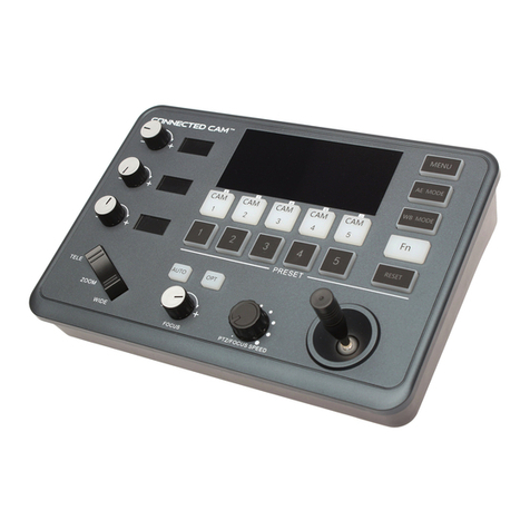
The DV-180 Controller tabletop version features a sloped front panel for ready access to all of the DV-180
Controller controls. Four RS-422 connectors are located on the rear of the unit to interface to each of the 4
remote camera sites. A 15 Pin D female connector is located on the rear of the DV-180. This connector
provides the interface to the user’s computer system for Camera Control functions. A computer program is
supplied with the DV-180 which provides Gain, Shutter and White Balance control of the GY-DV300.
Input power to the DV-180 Controller is provided by a wall mounted power supply which is provided with
the unit.
JVC DV-180 PAN/TILT Operations Manual Doc #: D0154-A
4

2. DV-180 CONTROLLER SPECIFICATIONS:
Operating Environment: ................................................... Indoor; contact factory for outdoor requirements
Temperature:..................................................................... 40 to 104 degrees F. (0 to 40 degrees C.)
Control Characteristics:
Power................................................................... Rocker Switch, with LED indicator
Pan/Tilt ................................................................ Joystick, proportional deflection
Focus.................................................................... Seesaw control, proportional deflection
Zoom.................................................................... Seesaw control, proportional deflection
Presets.................................................................. 8 per camera station
Number of Stations.............................................. 4
Max. distance between controller & p/t head ...... 2000 feet
Physical Characteristics:
Size (surface mount) ........................................... 9.75 (W) X 7.25 (D) inches; sloped chassis
Weight ................................................................. 4 Pounds
Mounting ............................................................. Table-top
Power Input Requirements:
Voltage................................................................. 12 VDC
Current................................................................. 0.3 Amperes
Wall Mount Power Supply .................................. Provided with Controller
Pan/Tilt Output Connector................................................ 4 conductor RJ-11 Jacks
Computer Interface Connector.......................................... 15 pin D (female)
JVC DV-180 PAN/TILT Operations Manual Doc #: D0154-A
5

3. INSTALLATION
Installation of the DV-180 Controller console version consists of merely attaching interface cables and
power module. The mounting hardware is the responsibility of the installer and is not provided with the
controller. The interface cables consist of up to four RS-422 cables to the DV-115 pan & tilt heads and one
RS-232 cable to the user’s computer.
3.1 TOOLS AND EQUIPMENT REQUIRED:
There are only two tools required to install the controller, they are: 1/8 inch flat blade screwdriver for the 15
pin remote (LDCC) “D” connector on the rear panel of the unit. This connector is only attached in the event
the computer based CCU option is included, and a #1 Phillips screwdriver for attaching the ground wire to
metal chassis in the event it is required.
3.2 RS-422 CABLE INSTALLATION
This interface is the normal connection between DV-180 controllers and the DV-115 pan and tilt heads. The
figure below illustrates a typical RS-422 interface cable. These cables are terminated with conventional
telephone type modular six position four contact connectors. Each camera station in the system must be
connected to the controller via a RS-422 cable. Connect one end of RS-422 to the connector on the rear of
the controller. Connect the other end of the cable to the connector on the pan and tilt head labeled “RS422”.
Note: pins 1 and 6 are not used.
960379-100
Black
Red
Green
Yellow
P/T Out -
P/T Out +
P/T In -
P/T In +
1
2
3
4
5
6
1
2
3
4
5
6
Figure 3-1: Typical RS-422 Cable
JVC DV-180 PAN/TILT Operations Manual Doc #: D0154-A
6

3.3 CAMERA CONTROL CABLE
If the Computer based Camera Control option is used with the DV-180, a cable is required on the 15-pin
connector located on the rear panel of the controller. To install the cable, connect the 15-pin plug (male) end
of cable (ACA203006600) to the rear panel of controller and connect the 9-pin end of the cable to the 9-pin
serial data connector on the computer.
3.4 GROUND WIRE
The DV-180 Controller is equipped with the provision for attaching a chassis ground to the metal controller
console. This ground helps eliminate static electricity problems and provides a hard earth ground if required.
A single 4-40 stainless steel screw is located adjacent to the power switch on the rear panel of the console
chassis. Fabricating the ground wire is the responsibility of the installer and is not provided with the
controller.
3.5 POWER MODULE
The power for the DV-180 Controller is supplied by a single wall mount power module. The unit requires a
12 VDC @ 500 ma version power module. To install the power module simply plug the unit into the AC
wall outlet and plug the DC plug into the jack on the rear panel of the DV-180 Controller labeled “POWER
+12 VDC”. Caution: in the event the power is supplied by the user the center pin of the plug is ground DO
NOT reverse the polarity.
3.6 POWER “ON” INDICATOR TEST
When the system is powered on, the green “PWR” indicator will be illuminated and the function LED’s
will sequence from all extinguished to all illuminated. This indicates the system is operating normally. The
power on test is complete when all indicators are extinguished with the exception of the green power
“ON” LED, and the camera 1 LED, which defaults to illuminated at the completion of the test.
3.7 ANALOG CONTROL CALIBRATION
Do not activate any analog controls (pan, tilt, zoom or focus) while the system is executing the power-up
sequence test. These analog pan, tilt, zoom, and focus controls are automatically calibrated during power-
on test.
JVC DV-180 PAN/TILT Operations Manual Doc #: D0154-A
7

4. FRONT PANEL-CONTROLS AND INDICATORS.
ZOOMFOCUS
NEAR FAR WIDE TELE
DN
RTLT
PRESET
12345678
PWR
DV-180 DIGITAL CONTROLLER
PGPRG 1234
CAMERA
UP
AUXILIARY
12
JVC
2
A/I BARS
RECORD
ST RC RV FF PAU A/F OP CL
IRIS
DV-180 Controller Console Front Panel
4.1 POWER SWITCH
The power switch on the DV-180 Controller is located on the lower area of the controller rear panel. To
apply power to the unit depress the bottom portion of the switch. The front panel green power LED will
illuminate indicating the power is on. Upon supplying power to the DV-180 Controller, the lamp test and
analog calibration self test will commence.
4.2 POWER INDICATOR
The power indicator for the DV-180 Controller is a green LED labeled “PWR”. This is an indication that the
power supply is connected and the power switch is in the “ON” position.
JVC DV-180 PAN/TILT Operations Manual Doc #: D0154-A
8

4.3 PAGE SWITCH AND INDICATOR
The function of the “PAGE” switch is to select preset positions one through eight, which are indicated by the
numbers over the switches, or to select recorder, auto focus, or manual iris functions, which are indicated by
the letters and symbols under the switches. The current page status is indicated by the illumination of the
page LED located in the “PAGE” switch located on the upper left area of the front panel. Preset positions
one through eight are selected if the LED is extinguished. Recorder, auto focus, or manual iris functions
are enabled if the LED is illuminated.
4.4 PROGRAM SWITCH AND INDICATOR
This switch and indicator are located adjacent to the “PAGE” switch on the upper left area of the front panel
and can be identified by the gray switch cap. This control is used to initiate the programming of one of the
eight presets when the “PAGE” LED is extinguished. If the “Program” LED is illuminated, depressing a
Preset switch will program a preset to that preset number. If the “Program” LED is extinguished, the
depression of a preset switch will send the pan & tilt head to preset location corresponding to the preset
switch depressed.
If the “PAGE” LED is illuminated, the “PROGRAM” switch turns the GY-DV300 Full Auto mode on or
off. If the “PROGRAM”LED is extinguished, the Full Auto Mode is “OFF”. If the “PROGRAM” LED is
illuminated, the Full Auto Mode is “ON”. Depressing the “PROGRAM” switch reverses the Full Auto
Mode.
4.5 CAMERA SELECT SWITCH AND INDICATOR
These four switches and indicators are centrally located on the upper area of the front panel. The camera to
be controlled is selected by depressing the appropriate switch. The red LED in the switch cap indicates
which camera is selected. Note: Upon power up the controller will always default to camera number one.
4.6 AUXILIARY 1 SWITCH AND INDICATOR
This switch and indicator are located on the upper right area of the front panel. As with the PRESET
switches the AUXILLARY 1 switch performs two different functions depending on the state of the PAGE
switch. If the LED in the PAGE switch is off, the AUX 1 switch controls the AUX 1 functions. If the LED
in the PAGE switch is on, the AUX 1 switch controls the auto iris mode of the camera.
The AUX1 switch is used in conjunction with the CAMERA SELECT and rear panel DIP switches to
allow reversal of the manual control functions and to vary the speed of certain control functions. The
functions of this switch will be discussed in depth in the operations section of this manual.
The Camera Auto/Manual Iris mode is toggled by depressing the AUX 1 switch when the “PAGE” LED
illuminated. The functions of this switch will also be discussed in depth in the operations section of this
manual
JVC DV-180 PAN/TILT Operations Manual Doc #: D0154-A
9

4.7 AUXILIARY 2 SWITCH AND INDICATOR
This switch and indicator is located adjacent to the “AUXILIARY 1” switch on the upper right area of the
front panel. The AUX2 switch is used to control the Color Bar/Camera mode when the “PAGE” LED is
lit. If the LED in the PAGE switch is off, the AUX 2 has no function. If the AUX2 LED is illuminated, the
Camera displays Bars. Conversely, if the AUX2 LED is extinguished, the camera is in its normal display
mode.
4.8 PRESET SWITCHES AND INDICATORS
There are eight preset switches with LED indicators. They are centrally located on the front panel of the DV-
180 Controller. As with the AUXILLARY 1 switch, the PRESET switches performs two different functions
depending on the state of the PAGE switch. These switches, in conjunction with the PAGE switch, allow the
user to set and go to eight unique preset positions for pan, tilt, zoom, and focus for each of the four (4)
camera stations. In addition, it is used to control the video recorder feature of the GY-DV300U and to toggle
auto focus, or to manually open or close the iris on the camera.
If the LED in the PAGE switch is off, the eight PRESET switches program and recall the eight presets for
each of the cameras.
If the LED in the PAGE switch is on, the left most five PRESET switches initiate commands to GY-DV-
300U video recorder. The commands are stop, record, rewind, fast forward, and pause. The sixth switch
toggles the auto focus mode of the camera. Switches seven and eight open and close the iris, if the camera
is in the manual iris mode.
4.9 ZOOM & FOCUS - SEESAWS CONTROLS
Located to the left of the pan and tilt joystick are the controls for zoom and focus. Control of the zoom and
focus is accomplished with proportional deflection “Seesaw” rocker type controls. The proportional controls
allow a slow movement when the control is only slightly depressed increasing to a maximum response when
the control is more fully depressed. These devices are automatically calibrated during the power up of the
DV-180 Controller.
4.10 JOYSTICK
Located on the lower right area of the front panel is the joystick. Control of the pan and tilt is accomplished
with proportional deflection action from the joystick. The proportional control allows a slow movement
when the rod is slightly deflected with an increasing response as the control is more fully deflected. The
joystick is automatically calibrated during the power up of the DV-180 Controller. The direction that the
joystick drives the pan and tilt may be reversed by using the setup switches on the DV-180 Controller rear
panel. These switches are used in conjunction with the AUX 1 switch. Direction reversal is discussed in the
operations section.
JVC DV-180 PAN/TILT Operations Manual Doc #: D0154-A
10

5. REAR PANEL-CONNECTORS AND SWITCHES
COMPUTER
CONTROL
POWER
+12 VDC
+-
CAM1 CAM2 CAM3 CAM4 SETUP
Made in USA
www.jvc.com S/N:
ON
12345678
Camera Controller for GY-DV300U
JVC
DV-180 Controller Rear Panel
5.1 COMPUTER CONTROL CONNECTOR
The female high density15 pin “D” connector located in the lower left area of the rear panel is labeled
“COMPUTER CONTROL”. This connector accepts a cable that allows a PC based camera control program
to communicate via the DV-180 Controller to individual cameras in the system. In this mode Camera
Control commands are sent via the DV-180 Controller to the individual pan and tilt heads using their RS-
422 communication links. The wiring for this RS-422 cable assembly is shown in the cable section.
5.2 CAMERA 1 - 4 CONNECTORS
These four, six conductor, four contact modular telephone type plugs are used to link the pan and tilt heads
to the DV-180 Controller. The control data for the pan and tilt head or the camera will go out the port that is
selected on the front panel by the camera select switches.
5.3 GROUND SCREW
The DV-180 Controller is equipped with a grounding screw to make provision for attaching a chassis ground
wire to the metal controller console. A single 4-40 Phillips head stainless steel screw is located adjacent to
the power switch on the rear panel of the DV-180 Controller console chassis.
5.4 DC JACK, POWER REQUIREMENTS
The DC power connection for the DV-180 Controller is the small circular 5.5 mm DC jack located on the
lower right area of rear panel on the DV-180 Controller. This connector accepts the power plug from the
small wall mount power modules supplied with the unit. The DC plug type connector that plugs into the DV-
180 Controller is a Switchcraft part number S760.
JVC DV-180 PAN/TILT Operations Manual Doc #: D0154-A
11

5.5 REAR PANEL DIP SWITCHES
The function of the DV-180 Controller set-up switches are shown below. To activate any of these
commands, verify the PAGE led is not illuminated, put the desired command DIP switch in the DOWN
position, depress the CAMERA SELECT switch and then depress and release the AUXILIARY 1 switch
as described in the tilt example. Switches 3 – 6 are unused and should remain “OFF”.
ON
12345678
Pan Reverse
Tilt Reverse
Reserved
Reserved
Reserved
Reserved
Speed Range 1
Speed Range 0
REAR PANEL DIP SWITCH
The Function of each of these switches is as follows:
SW8 Pan Reverse
• Up: Normal pan direction, left on joystick camera pans to the left.
• Down: Reverse pan direction, left on joystick camera pans to the right
SW7 Tilt Reverse
• Up: Normal tilt direction, up on joystick camera tilts up.
• Down: Reverse tilt direction, up on joystick camera tilts down.
SW2 Speed Range 1
SW1 Speed Range 0
• The Speed Range bits are used to the vary the speed of the joystick and seesaw controls. With both
switches Up the maximum speed is enabled and with both switches down the minimum speed is
enabled
JVC DV-180 PAN/TILT Operations Manual Doc #: D0154-A
12

5.6 RS-422 CONNECTORS
The four connectors labeled “CAM1”, “CAM2”, “CAM3”, and “CAM4” on the connector plate are six
position, four conductor modular jacks. This connector provides RS-422 level differential signals to and
from the digital pan and tilt head. The RS-422 is the interface from the controller to the pan and tilt heads.
Shown below is the pin-out for the RS-422 connector. The pin assignment for this connector follows:
Pin 2 Pin 5 Pin 6
Not
Used
Pin 1
Not
Used
The camera connector pin assignment:
Pin # Description
2 P/T Data Out - (Data In to the DV-180 Controller)
3 P/T Data Out +
4 P/T Data In - (Data Out of the DV-180 Controller)
5 P/T Data In +
JVC DV-180 PAN/TILT Operations Manual Doc #: D0154-A
13

6 DV-180 PC COMM
The DV-180 PC COMM is a software program designed to run on a Windows platform and to
control select camera features. The screenshot below illustrates the DV-180 PC COMM.
The 2030066 cable provided with the system is the interface between the DV-180 and the computer.
Connect the 9 pin “D” connector to the serial port on the computer and the fifteen pin “D” Sub connector on
the rear of the DV-180 Controller.
To install the PC COMM Program, double click on the setup.exe program in the PC-COMM Folder. If the
installation is unsuccessful, manually move the file MSCOMM32.OCX (located in the Support folder) to
your Windows/System directory. Double click on the ESI DV-180 PC COMM.exe file and hopefully all is
well.
When operating the PC COMM program, it will initially load its default values. Select a camera on the DV-
180 Controller front panel and make sure the PAGE LED is illuminated and the PROGRAM LED is
extinguished. Vary each of the PC COMM controls. This will re-synchronize the PC COMM program to the
camera settings. This should be done for each camera in the system. After the initial re-synchronize, the PC
COMM program will store the current values of the camera.
The PC COMM program operates much like a typical Camera Control Unit. It will only work, if it is
connected to the DV-180. Special code exists in the PC COMM command structure to tell the DV-115 to
switch the incoming data directly to the GY-DV300REM. Directly interfacing the PC COMM program to
the camera WILL NOT WORK.
JVC DV-180 PAN/TILT Operations Manual Doc #: D0154-A
14

7. OPERATION
7.1 COMMUNICATION INTERFACE
Control of the pan and tilt is accomplished by sending packets of serial characters to the DV-115. Camera
related commands are converted to RS-232 level and routed through the DV-115 to the camera. The standard
communications protocol is 9600 baud, eight data bits, one stop bit, and no parity. These commands tell the
pan and tilt head and camera which operations to perform Preset related commands are also passed over the
communication link between the head and the controller.
7.2 POWER ON
When the system is powered up, all LED’s will sequence individually indicating the system is operating
normally. All LED’s will extinguish with the exception of CAM1. The controller defaults to camera
number one at the completion of the power on sequence. Do not activate any analog controls (pan, tilt,
zoom or focus) while the system is in the power-up sequence. These analog controls are automatically
calibrated during power-up. Camera modes setting will be the same as they were when the DV-180
controller was last powered off.
7.3 MANUAL OPERATION
Select the desired camera by depressing the appropriate CAMERA select switch. The selected camera
LED will be lit and the camera location will be under the control of the DV-180 Controller. Camera 1 is
the default selection at power up. To position the selected pan & tilt head, move the joystick up, down, left
and right. To change the zoom, depress the TELE or the WIDE side of the ZOOM control. To change the
focus, depress the FAR or NEAR side of the FOCUS control.
7.4 PROGRAMMING A PRESET LOCATION
To program the preset location, first verify the PAGE LED is not illuminated, depress the gray
“PRG” switch and the amber PRG LED will be lit. Then position the pan & tilt head and the lens
zoom & focus to the desired positions and depress the desired preset location switch. Note: if the
camera is in the auto focus mode the operator will have no manual control with the focus seesaw at
this time. The individual preset numbered LED will then be illuminated at the point in time when
the desired preset switch is depressed. The current location data has now been stored in the desired
preset location. The program LED will cease to be lit after the preset location is selected or when
the “PRG” switch is depressed a second time.
Note: The preset storage is accomplished within the DV-115. A “Goto” command to preset
location “1” will command the DV-115 to go to the preset location data stored in location #1.
JVC DV-180 PAN/TILT Operations Manual Doc #: D0154-A
15

7.5 TO GO TO A PRESET LOCATION:
Verify the LED in the “PAGE” switch in not illuminated, depress the desired preset location and the
selected camera will go to the stored pan, tilt, zoom & focus location. That particular preset LED will
illuminate when the switch is depressed. Activating any manual control will interrupt the process of going
to a preset. When at the preset location, the preset location LED will remain lit until another preset is
selected or any manual control is activated.
7.6 DV-180 PC COMM
The DV-180 PC COMM is a software program that runs on the user’s personal computer. The user’s PC
must have a CD and at least one external serial port. This program performs limited camera control unit
functions and communicates with the DV-180, the DV-115, and the GY-DV300 camera via a RS-232
cable interface. The part number for the cable is 2030066; the standard length for this cable is three feet.
This cable is connected between the serial port on the computer and the fifteen pin “D” Sub connector on
the rear of the DV-180 Controller.
Once installed on the user’s computer the DV-180 PC COMM program provides control for the GY-
DV300 video gain, white balance, and shutter for each camera connected to the system. The program
remembers the parameters that are set using the DV-180 PC COMM. If the controller is powered off the
configuration of the camera set up is not lost. These parameters are restored for the camera when the
controller is powered back on.
7.7 TO REVERSE MANUAL CONTROL FUNCTIONS
To reverse the directions of the manual functions of the DV-180 Controller use the SETUP switches
located on the rear panel of the DV-180 Controller chassis. These switches used in conjunction with the
CAMERA SELECT and the AUXILIARY 1 switches to allow reversal of the pan and tilt manual control
functions. For example, it may be necessary to reverse the direction of motion of the tilt head because the
system is being operated by a aircraft pilot. To reverse the tilt function for camera 1, perform the following
steps:
Put the SETUP Switch #7(Tilt Reverse) in the DOWN position, depress the CAMERA SELECT 1 switch
and hold it down. Depress and release the AUXILIARY 1 switch while the CAMERA SELECT 1 switch
is still depressed. Release the CAMERA SELECT 1 switch. The tilt function is now reversed for camera 1
only. To reverse the tilt function of camera 2, repeat the above procedure with the CAMERA SELECT 2
switch depressed instead of the CAMERA SELECT 1 switch. To the restore the normal polarity of the tilt
control, simply repeat the above procedure with DIP Switch #7 in the UP position.
7.8 TO SET THE SPEED RANGE
To set the speed range of the manual functions of the DV-180 Controller also use the SETUP switches
JVC DV-180 PAN/TILT Operations Manual Doc #: D0154-A
16

located on the rear panel of the DV-180 Controller.
These switches used in conjunction with the CAMERA SELECT switches and the AUXILIARY 1 switch
allow setting the speed range of the joystick and seesaw manual control functions. For example, it may be
necessary to slow the motion of the pan & tilt head because very smooth control is needed for “on air”
moves. To change the speed range for camera 1, perform the following steps:
Put the SETUP Switch #1(Speed Range bit 1) in the DOWN position, depress the CAMERA SELECT 1
switch and hold it down. Depress and release the AUXILIARY 1 switch while the CAMERA SELECT 1
switch is still depressed. Release the CAMERA SELECT 1 switch. The Speed Range has now been slowed
for camera 1 only. To change the Speed Range of camera 2, repeat the above procedure with the CAMERA
SELECT 2 switch depressed instead of the CAMERA SELECT 1 switch. For the highest speed operation,
load with both switches in the up position. For the slowest speed operation, load with both switches in the
down position.
7.9 VIDEO RECORDER CONTROLS
There are five video recorder control commands available from the front panel of the DV-180, they are: stop,
record, rewind, fast-forward, and pause. These controls use the preset switches 1-5. To activate these
controls, verify the PAGE LED is illuminated indicating the functions listed under the PRESET switches are
enabled, and then depress desired tape command.
7.10 AUTO FOCUS
There is an auto focus command available from the front panel of the DV-180. This control use the preset
switches 6. To activate auto focus, verify the PAGE LED is illuminated indicating the functions listed under
the PRESET switches are enabled.
7.11 MANUAL IRIS
There is two manual iris control commands available from the front panel of the DV-180, they are: open and
close. These controls use the preset switches 7 and 8. To activate these controls, verify the PAGE LED is
illuminated indicating the functions listed under the PRESET switches are enabled, and then depress desired
iris command.
7.12 AUTO IRIS
There is an auto iris control command available from the front panel of the DV-180, this function is labeled
A/I. This controls uses the preset switch 6. To activate these controls, verify the PAGE LED is illuminated
indicating the functions listed under the AUXILLLARY 1 switch is enabled, and then depress A/I (PRESET
6) switch.
JVC DV-180 PAN/TILT Operations Manual Doc #: D0154-A
17

7.13 COLOR BAR GENERATION
An industry standard color bar pattern can be generated from the GY-DV300U camera. To activate this
control, verify the PAGE LED is illuminated indicating the functions listed under the AUILLARY 2 switch
is enabled, and then depress AUILLARY 2 switch, color bars will be displayed on monitor. To disable the
bars depress the switch again.
7.14 CABLE DRAWINGS
Attached are the two applicable cable drawings for the DV-180 Controller, these include; drawing 960379
the RS-422 I/F cable between the DV-180 Controller and the pan and tilt heads and drawing 2030066, the
RS-232 cable between the DV-180 Controller the user’s personal computer.
1
3
2X
Pin 1
2
Blk
Red
Grn
Yel
.25 In.
ACA96037900
1. Strip jacket .375 Inches.
2. Fan and flatten to color pattern.
3. Trim straight to .250 Inches.
4. Insert in connector and crimp
Black
Red
Green
Yellow
P/T Tx -
P/T Tx +
P/T Rx -
P/T Rx +
2
3
4
5
2
3
4
5
6 Inches.
RS-422 INTERFACE CABLE, P/N ACA96037900
JVC DV-180 PAN/TILT Operations Manual Doc #: D0154-A
18

9 Pin Female
Receptacle
ACA203006600
BLK
2
3
5
3
2
15
15 Pin Male
(Plug)
DATA TO DV-180
GROUND
YEL
RED
12345
78910
6
11 12 13 14 15
DATA TO PC
12345
789
6
DV-180/PC COMM CABLE, P/N ACA203006600
JVC DV-180 PAN/TILT Operations Manual Doc #: D0154-A
19

JVC DV-180 PAN/TILT Operations Manual Doc #: D0154-A
20
8. TROUBLE SHOOTING
8.1 PAN & TILT
Problem: No pan/tilt or lens functions.
Verify proper power is supplied to controller.
Verify “AUX2” switch is not depressed.
Verify the interface cable is properly installed.
8.2 DV-180 PC COMM
Problem: No CCU functions.
Verify correct Comm port is selected for your computer.
Verify configuration of 3 conductor RS-232 interface cable, P/N 2030066.
8.3 TECHNICAL SUPPORT
For technical assistance on the DV-180 call (321) 956-0095 or go to web site at esi-inc.com. Have serial
number of unit and description of symptoms available.
Table of contents
Other JVC Controllers manuals
Popular Controllers manuals by other brands

ICT
ICT Protege SE installation manual

Pilz
Pilz PSEN sl-1.0p 4.2 operating manual

Avigilon
Avigilon AC-HID-LSP-ACMEC-KIT4 installation guide

iNels
iNels RFDEL-76M manual

Edgewater Networks
Edgewater Networks EdgeMarc 4800 Hardware installation guide

Albalá Ingenieros, S.A.
Albalá Ingenieros, S.A. TLE3100C02 manual

Sumpo Electric Co., Ltd.
Sumpo Electric Co., Ltd. P9000 instruction manual

SEW
SEW movidrive md_60a user manual

DOGA
DOGA HDC-30i instruction manual

Shinko
Shinko FCR-13A instruction manual

National Instruments
National Instruments NI 3100 user manual

Ascon tecnologic
Ascon tecnologic KM Series Quick programming guide