JVC TH-P7 User manual

LVT1523-001B
[B]
DVD DIGITAL CINEMA SYSTEM
INSTRUCTIONS
(Only for TH-P7/TH-P5)
TH-P5
Consists of XV-THP5, SP-WP5,
SP-THP5F, SP-THP5C and SP-THP5S
TH-P3
Consists of XV-THP3, SP-WP5,
SP-THP3F, SP-THP3C and SP-THP3S
TH-P7
Consists of XV-THP7, SP-WP7,
SP-THP7F, SP-THP7C and SP-THP7S
EN_THP7-P5-P3[B]-rev4.book Page i Thursday, March 2, 2006 6:59 PM

G-1
IMPORTANT for the U.K.
DO NOT cut off the mains plug from this equipment.
If the plug fitted is not suitable for the power points in
your home or the cable is too short to reach a power
point, then obtain an appropriate safety approved
extension lead or consult your dealer.
BE SURE to replace the fuse only with an identical
approved type, as originally fitted.
If nonetheless the mains plug is cut off ensure to
remove the fuse and dispose of the plug immediately,
to avoid a possible shock hazard by inadvertent
connection to the mains supply.
If this product is not supplied fitted with a mains plug
then follow the instructions given below:
IMPORTANT.
DO NOT make any connection to the terminal which
is marked with the letter E or by the safety earth
symbol or coloured green or green-and-yellow.
The wires in the mains lead on this product are
coloured in accordance with the following code:
Blue: Neutral
Brown: Live
As these colours may not correspond with the coloured
markings identifying the terminals in your plug
proceed as follows:
The wire which is coloured blue must be connected to
the terminal which is marked with the letter N or
coloured black.
The wire which is coloured brown must be connected
to the terminal which is marked with the letter L or
coloured red.
IF IN DOUBT - CONSULT A COMPETENT
ELECTRICIAN.
CAUTION
To reduce the risk of electrical shocks, fire, etc.:
1. Do not remove screws, covers or cabinet.
2. Do not expose this appliance to rain or moisture.
CAUTION— button!
Disconnect the mains plug to shut the power off
completely (the STANDBY lamp goes off). When
installing the apparatus, ensure that the plug is easily
accessible.
The button in any position does not disconnect the
mains line.
• When the system is on standby, the STANDBY lamp
lights red.
• When the system is turned on, the STANDBY lamp
goes off.
The power can be remote controlled.
CAUTION
• Do not block the ventilation openings or holes.
(If the ventilation openings or holes are blocked by a
newspaper or cloth, etc., the heat may not be able to
get out.)
• Do not place any naked flame sources, such as
lighted candles, on the apparatus.
• When discarding batteries, environmental problems
must be considered and local rules or laws governing
the disposal of these batteries must be followed
strictly.
• Do not expose this apparatus to rain, moisture,
dripping or splashing and that no objects filled with
liquids, such as vases, shall be placed on the
apparatus.
IMPORTANT FOR LASER PRODUCTS
1. CLASS 1 LASER PRODUCT
2. CAUTION: Do not open the top cover. There are no user
serviceable parts inside the unit; leave all servicing to qualified
service personnel.
3. CAUTION: Visible and/or invisible class 1M laser radiation
when open. Do not view directly with optical instruments.
Warnings, Cautions and Others
EN_THP7-P5-P3[B]-rev4.book Page 1 Thursday, March 2, 2006 6:59 PM

G-2
Caution: Proper Ventilation
To avoid risk of electric shock and fire and to protect from damage, place the apparatus on a level surface. The minimal
clearances are shown below:
15 cm
Wall or
obstructions
XV-THP7/
XV-THP5/
XV-THP3
15 cm
15 cm
15 cm
XV-THP7/
XV-THP5/
XV-THP3
15 cm
Front
No
obstructions
Wall or
obstructions
Information for Users on Disposal of Old Equipment
[European Union]
Attention:
This symbol is only valid
in the European Union.
This symbol indicates that the electrical and electronic equipment should not be
disposed as general household waste at its end-of-life. Instead, the product should
be handed over to the applicable collection point for the recycling of electrical and
electronic equipment for proper treatment, recovery and recycling in accordance
with your national legislation.
By disposing of this product correctly, you will help to conserve natural resources
and will help prevent potential negative effects on the environment and human
health which could otherwise be caused by inappropriate waste handling of this
product. For more information about collection point and recycling of this product,
please contact your local municipal office, your household waste disposal service or
the shop where you purchased the product.
Penalties may be applicable for incorrect disposal of this waste, in accordance with
national legislation.
(Business users)
If you wish to dispose of this product, please visit our web page www.jvc-europe.com
to obtain information about the take-back of the product.
[Other Countries outside the European Union]
If you wish to dispose of this product, please do so in accordance with applicable
national legislation or other rules in your country for the treatment of old electrical
and electronic equipment.
Front view Side view
EN_THP7-P5-P3[B]-rev4.book Page 2 Thursday, March 2, 2006 6:59 PM

1
Introduction ...........................................2
Notes on handling ......................................................... 2
Supplied accessories ...................................................... 2
About discs .............................................3
Playable disc types ......................................................... 3
Playable file types .......................................................... 4
Index of parts and controls ...................5
Connections ............................................7
Connecting the FM and AM (MW) antennas .......... 7
Connecting the satellite (front, center, surround)
speakers and the subwoofer ......................................... 8
Speaker layout .............................................................. 12
Connecting a TV ......................................................... 12
Connecting a USB mass storage class device .......... 13
Connecting the power cord ....................................... 13
Operating the TV ..................................14
Basic operations ...................................15
Turning the system on/off ......................................... 15
Selecting the source to play ........................................ 16
Adjusting the volume [VOLUME] ........................... 16
Listening with headphones (not supplied) .............. 16
Turning off the sound temporarily [MUTING] ..... 16
Adjusting the brightness of the indications
[DIMMER] ................................................................... 16
Sleep Timer [SLEEP] .................................................. 17
Adjusting the output level of the front/center/
surround speakers and subwoofer ............................ 17
Changing scan mode .................................................. 17
Playback ...............................................18
Basic Playback ..............................................................18
One Touch Replay .......................................................20
Fast-forward/fast-reverse search ................................20
Skip to the beginning of a desired selection .............20
Skipping at about 5-minute intervals.........................21
Locating a desired title/group using number buttons ....
21
Selecting the desired title/playlist from the control
display ............................................................................21
Advanced operations ..........................22
Using the surround mode ...........................................22
Using the on-screen bar ..............................................23
Playing from a specified position on a disc ..............25
Using the file control display ......................................26
Resume Playback ..........................................................27
Selecting a view angle ..................................................27
Selecting the subtitle ....................................................28
Selecting the audio .......................................................28
Special picture playback ..............................................29
Program Playback ........................................................30
Random Playback ........................................................30
Repeat Playback ...........................................................31
Tray lock ........................................................................32
Balance Setting .............................................................32
Setting DVD preferences .....................33
Using the setup menus ................................................33
Menu description .........................................................33
Tuner operations .................................36
Manual tuning ..............................................................36
Preset tuning .................................................................36
Selecting the FM reception mode ..............................37
Using the Radio Data System when receiving FM
stations ...........................................................................37
References ............................................40
Maintenance .................................................................40
Troubleshooting ...........................................................40
Specifications ................................................................41
I
Table of contents
EN_THP7-P5-P3[B]-rev4.book Page 1 Thursday, March 2, 2006 6:59 PM

2
Introduction
7Important cautions
Installation of the system
• Select a place which is level, dry and neither too hot nor
too cold; between 5°C and 35°C.
• Leave sufficient distance between the system and the TV.
• Do not use the system in a place subject to vibration.
Power cord
• Do not handle the power cord with wet hands.
• A small amount of power is always consumed while the
power cord is connected to the wall outlet.
• When unplugging the power cord from the wall outlet,
always pull on the plug, not the power cord.
To prevent malfunctions of the system
• There are no user-serviceable parts inside. If anything
goes wrong, unplug the power cord and consult your
dealer.
• Do not insert any metallic object into the system.
• Do not use any non-standard shape disc (like a heart,
flower or credit card, etc.) available on the market,
because it may damage the system.
• Do not use a disc with tape, stickers, or paste on it,
because it may damage the system.
Note about copyright laws
Check the copyright laws in your country before recording
from the discs. Recording of copyrighted material may
infringe copyright laws.
Note about copyguard system
The discs are protected by copyguard system. When you
connect the system to your VCR directly, the copyguard
system activates and the picture may not be played back
correctly.
7Safety precautions
Avoid moisture, water and dust
Do not place the system in moist or dusty places.
Avoid high temperatures
Do not expose the system to direct sunlight and do not
place it near a heating device.
When you are away
When away on travel or for other reasons for an extended
period of time, disconnect the power cord plug from the
wall outlet.
Do not block the vents
Blocking the vents may damage the system.
Care of the cabinet
When cleaning the system, use a soft cloth and follow the
relevant instructions on the use of chemically-coated cloths.
Do not use benzene, thinner or other organic solvents
including disinfectants. These may cause deformation or
discoloring.
If water gets inside the system
Turn the system off and disconnect the power cord plug
from the wall outlet, then call the store where you made
your purchase. Using the system in this condition may
cause a fire or electrical shock.
Check to be sure you have all of the supplied accessories.
The number in parentheses is the quantity of the pieces
supplied.
If anything is missing, contact your dealer immediately.
• Remote control (1)
• Batteries (2)
• FM antenna (1)
• AM loop antenna (1)
• Speaker cords (Only for TH-P7)
4 m: For satellite (front left/right), center speakers, and
subwoofer (4)
10 m: For satellite speakers (surround left/right) (2)
•Screws(OnlyforTH-P7)
M5 x40 mm (4)
M4 x20 mm (8)
• Speaker cord clamps (Only for TH-P7) (4)
Notes on handling
Paste
Sticker
Label sticker Supplied accessories
EN_THP7-P5-P3[B]-rev4.book Page 2 Thursday, March 2, 2006 6:59 PM

3
About discs
This system has been designed to play back the following
discs:
The √in the list below shows available disc types and
recording formats.
*1This system can play finalized discs only.
*2Recorded with UDF Bridge format.
*3This system may not be able to play back a file if the file
size is too large.
• It is possible to play back finalized +R/+RW (DVD Video
Format only) discs. “DVD” lights on the display panel
when a +R/+RW disc is loaded.
• This system accommodates the PAL system, and also can
play discs recorded with NTSC system. Note that an
NTSC video signal on a disc is converted to the PAL60
signal and output.
• The Non-DVD side of a “DualDisc” does not comply
with the “Compact Disc Digital Audio” standard.
Therefore, the use of Non-DVD side of a DualDisc on
this product may not be recommended.
• On some DVD VIDEOs, VCDs or SVCDs, their actual
operation may be different from what is explained in
this manual. This is due to the disc programming and
disc structure, not a malfunction of this system.
DVD Logo is a trademark of DVD Format/Logo Licensing
Corporation.
Notes on DVD-R and DVD-RW
• This system does not support “multi-border” disc.
Notes on CD-R and CD-RW
• This system can play CD-Rs or CD-RWs recorded with
ISO 9660 format.
• This system supports “multi-session” discs (up to 20
sessions).
• This system cannot play “packet write” discs.
Region code of DVD VIDEO
DVD VIDEO players and DVD VIDEO discs have their
own Region Code numbers. This system can play back
DVD VIDEO discs whose Region Code numbers include
the system’s Region Code, which is indicated on the rear
panel.
If a DVD with an improper Region Code number is loaded,
“REGION CODE ERROR!” appears on the TV screen and
playback cannot start.
Some discs may not be played back because of their disc
characteristics, recording conditions, or damage or stain on
them.
Playable disc types
DVD VIDEO Audio CD
VCD SVCD
Disc type
CD-R/-RW
*1DVD-R*1DVD-RW*1
Recording
format
DVD Video — √√
DVD VR — √√
VCD/SVCD √——
Audio CD √——
MP3 √√*2√*2
WMA √√*2√*2
JPEG √√*2√*2
ASF √√*2√*2
MPEG-2 √*3√*2√*2
MPEG-1 √*3√*2√*2
DivX √√*2√*2
Unplayable discs
DVD-ROM, DVD-RAM, CD-I (CD-I Ready), Photo CD,
SACD, etc.
Playing back these discs will generate noise and damage
the speakers.
Example of playable DVD:
EN_THP7-P5-P3[B]-rev4.book Page 3 Thursday, March 2, 2006 6:59 PM

4
About discs
For all playable files
• The system can only recognize and play files with one of
the following extensions, which can be in any
combination of upper and lower case;
MP3: “.MP3”, “.mp3”
WMA: “.WMA”, “.wma”
JPEG: “. J P G”, “. JP E G”, “.jpg ”, “. j p e g”
ASF: “. A SF ”, “. a s f ”
MPEG-2/MPEG-1:“.MPG”, “.MPEG”, “.mpg”, “.mpeg”
DivX: “.DIVX”, “.DIV”, “.divx”, “.div”, and “.AVI”, “.avi”
• The system recognizes up to 150 tracks (files) per group,
99 groups per disc/device, and the total number of the
tracks (files) that the system can play is 4000.
• Some files may not be played back normally because of
their disc characteristics or recording conditions.
• MP3/WMA/JPEG/ASF/MPEG-2/MPEG-1/DivX files
require a longer readout time. (It differs due to the
complexity of the directory/file configuration.)
• If different kinds of files are mixed, set the FILE TYPE
setting in the PICTURE menu to the appropriate setting
for the data to be read (“AUDIO”, “STILL PICTURE” or
“VIDEO”). (See page 34.)
For MP3/WMA files
• The system supports MP3/WMA files recorded with a bit
rate of 32 – 320 kbps and a sampling frequency of 16 kHz,
22.05 kHz, 24 kHz*, 32 kHz, 44.1 kHz, or 48 kHz.
• If the track information (album name, artist, and track
title, etc.) is recorded, it appears in the file control display
on the TV screen. (See page 26.)
• We recommend to record each piece of material (song) at
a sample rate of 44.1 kHz and at a data transfer rate of 128
(96*) kbps.
*For WMA only
For JPEG files
• We recommend to record a file at 640 x480 resolution. (If
a file has been recorded at a resolution of more than 640 x
480, it will take a longer time to be displayed.)
• This system can only play baseline JPEG files.
For ASF files
• The system supports the types of the advanced simple
profile as MPEG-4 files (MPEG-4 ASF).
• The system supports MPEG-4 files with the following
conditions:
File format: ASF
Visual profile: MPEG-4 SP (Simple Profile)
Audio CODEC: G.726
Max. picture size: 352 x288 (CIF)
Max. bit rate: 384 kbps
For MPEG-2/MPEG-1 files
• The stream format should conform to MPEG system/
program stream.
• 720 x576 pixels (25 fps)/720 x480 pixels (30 fps) is
recommended for the highest resolution.
• This system also supports the resolutions of 352 x576/
480 x576/352 x288 pixels (25 fps) and 352 x480/480 x
480/352 x240 pixels (30 fps).
• The file format should be MP@ML (Main Profile at Main
Level)/SP@ML (Simple Profile at Main Level)/MP@LL
(Main Profile at Low Level).
• Audio streams should conform to MPEG1 Audio Layer-2
or MPEG2 Audio Layer-2.
For DivX files
• The system supports DivX 6.x, 5.x, 4.x and 3.11.
• The system supports DivX files whose resolution is 720 x
480 pixels or less (30 fps), and 720 x576 pixels or less
(25 fps).
• Audio stream should conform to Dolby Digital
(including multi channel) or MPEG1 Audio Layer-3
(MP3).
• The system does not support GMC (Global Motion
Compression).
• The file encoded in the interlaced scanning mode may
not be played back correctly.
• The system has its own Registration Code for DivX
playback.
If necessary, you can confirm the Registration Code of
your system using the OTHERS menu. (See page 35.)
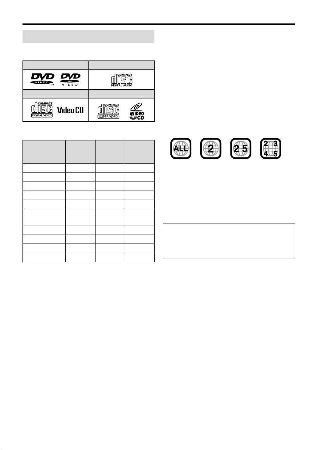
Playable file types
• This product incorporates copyright protection
technology that is protected by U.S. patents and other
intellectual property rights. Use of this copyright
protection technology must be authorized by
Macrovision, and is intended for home and other
limited viewing uses only unless otherwise authorized
by Macrovision. Reverse engineering or disassembly is
prohibited.
• “CONSUMERS SHOULD NOTE THAT NOT ALL
HIGH DEFINITION TELEVISION SETS ARE FULLY
COMPATIBLE WITH THIS PRODUCT AND MAY
CAUSE ARTIFACTS TO BE DISPLAYED IN THE
PICTURE. IN CASE OF 525 OR 625 PROGRESSIVE
SCAN PICTURE PROBLEMS, IT IS
RECOMMENDED THAT THE USER SWITCH THE
CONNECTION TO THE ‘STANDARD DEFINITION’
OUTPUT.
IF THERE ARE QUESTIONS REGARDING OUR TV
SET COMPATIBILITY WITH THIS MODEL 525p
AND 625p DVD PLAYER, PLEASE CONTACT OUR
CUSTOMER SERVICE CENTER.”
• USE OF THIS PRODUCT IN ANY MANNER THAT
COMPLIES WITH THE MPEG-4 VISUAL
STANDARD IS PROHIBITED, EXCEPT FOR USE BY
A CONSUMER ENGAGING IN PERSONAL AND
NON-COMMERCIAL ACTIVITIES.
• DivX, DivX Ultra Certified, and associated logos are
trademarks of DivX, Inc. and are used under license.
• Official DivX®Ultra Certified product
• Plays all versions of DivX®video (including DivX®6)
with enhanced playback of DivX®media files and the
DivX®Media Format
EN_THP7-P5-P3[B]-rev4.book Page 4 Thursday, March 2, 2006 6:59 PM

5
Index of parts and controls
The numbers in the figures indicate the pages where the details of the parts are described.
Front panel (center unit)
Rear panel (center unit)
Display window
22 36 19 23
19 36
37 39
18
18
18
16
Disc tray (inside): 18 Remote sensor: 6
18
16
16
15
19 30
19
15
27
31
30Only for TH-P7/TH-P5: 17
13
36
21
9-11 12
7
13
Only for TH-P7/TH-P5: 12
EN_THP7-P5-P3[B]-rev4.book Page 5 Thursday, March 2, 2006 6:59 PM

6
Index of parts and controls
Remote control Putting batteries in the remote control
If the range or effectiveness of the remote control decreases,
replace both batteries.
CAUTION
• Do not expose batteries to heat or flame.
Operating the system from the remote
control
Aim the remote control directly to the front panel of the
center unit.
• Do not block the remote sensor.
Number
buttons: 20
15
16
21, 25, 33
19, 37
16, 18
18, 36
16, 18
20, 29
28, 29
27, 28
18, 37
30
17
14, 16, 17, 25,
27, 29, 31, 32,
33, 37, 38
30
14
14
21
21, 25,
32
17, 21,
33, 37
23
16, 36
20, 36
23
20, 25
16
17, 29
14, 16
14, 17
31
31 17
16
R6P (SUM-3)/AA (15F) type dry-cell batteries
(supplied)
EN_THP7-P5-P3[B]-rev4.book Page 6 Thursday, March 2, 2006 6:59 PM

7
Connections
7AM (MW) loop antenna
Setting up supplied AM (MW) loop antenna
Connecting AM (MW) loop antenna
• Turn the loop antenna until you have the best reception
during AM (MW) broadcast program reception.
NOTE
• Make sure the antenna conductors do not touch any other
terminals, connecting cords or power cords. This could cause
poor reception.
If reception is poor
7FM antenna
If reception is poor
NOTE
• We recommend that you use coaxial cable for the FM
antenna as it is well-shielded against interference.
Connecting the FM and AM
(MW) antennas
If the antenna cord is covered with the
insulation coat, twist and pull the
insulation coat off and remove.
White Black
Outdoor single vinyl-covered wire
antenna (not supplied)
AM (MW) loop
antenna (white)
Center unit
Extend the supplied FM antenna
horizontally.
Center unit FM antenna (supplied)
Outdoor FM antenna (not
supplied)
Outdoor FM antenna cord
(not supplied)
Center unit
Standard type (75 Ω
coaxial) connector
Do not connect the power cord until all other connections have been made.
EN_THP7-P5-P3[B]-rev4.book Page 7 Thursday, March 2, 2006 6:59 PM

8
Connections
7Assembling the front and surround speakers for
TH-P7
• Check the model name of each speaker from the label
on the rear to locate each speaker correctly.
Before assembling —
• Prepare a Phillips screwdriver (not supplied).
• Take care not to drop any component part while
assembling; otherwise, it may cause damage to the floor
or personal injury.
Precautions for daily use
• When moving the speakers, do not pull the speaker
cords; otherwise, the speakers may fall over, causing
damage or injury.
• When holding a speaker, always grasp the lower portion.
• Do not lean against the speakers, as the speakers could
fall down or break, possibly causing an injury. Especially
be careful that children do not lean against them.
• Do not reproduce sounds at so high a volume that the
sound is distorted; otherwise, the speakers may be
damaged by internal heat buildup.
Connecting the satellite (front, center, surround) speakers and
the subwoofer
Assembled speakers:
With stand: Refer to steps 1
to 3.
Without stand: Refer to steps
2 and 3.
Front speaker
(SP-THP7F) (2)
Stand (4) Base plate (4)Surround
speaker
(SP-THP7S) (2)
or
Stand
Screw M5 x 40 mm
(supplied)
Speaker
1
2
Stand (or speaker
directly)*
Base plate
Screw M4 x 20 mm
(supplied)*
When assembling a speaker without stand:
Speaker
A: Use these screws (M4 x
45 mm) when assembling the
speaker with the base plate.
*When assembling the speaker with the base plate,
use the screws A.
3
Red White
Black Black
You can route the speaker cord
by using speaker cord clamp
(supplied).
Do not connect the power cord until all other connections have been made.
EN_THP7-P5-P3[B]-rev4.book Page 8 Thursday, March 2, 2006 6:59 PM

9
Connections
7Connecting speakers for TH-P7
CAUTION
• If you connect speakers other than the supplied ones, use
speakers of the same speaker impedance (SPEAKER
IMPEDANCE) indicated on the rear of the center unit.
• DO NOT connect more than one speaker to one speaker
terminal.
• When installing the satellite speakers on the wall;
– Be sure to have them installed on the wall by qualified
personnel.
DO NOT install the satellite speakers on the wall by
yourself to avoid unexpected damage from falling off the
wall due to incorrect installation or weakness in wall
structure.
– Care must be taken in selecting a location for speaker
installation on a wall. Injury to personnel or damage to
equipment may result if the speakers installed interfere
with daily activities.
SP-THP7C
Center speaker
• Connect the black cords to the black (–) terminals.
• Connect the white cords to the red (+) terminals.
Speaker cord
SP-WP7
Subwoofer
SP-THP7S
Surround
speakers
Before connecting
the speaker cords;
Twist and pull the
insulation coat off
and remove.
SP-THP7F
Front speakers
White
Black
Black Red
Do not connect the power cord until all other connections have been made.
EN_THP7-P5-P3[B]-rev4.book Page 9 Thursday, March 2, 2006 6:59 PM

10
Connections
7Connecting speakers for TH-P5
CAUTION
• If you connect speakers other than the supplied ones, use
speakers of the same speaker impedance (SPEAKER
IMPEDANCE) indicated on the rear of the center unit.
• DO NOT connect more than one speaker to one speaker
terminal.
• When installing the satellite speakers on the wall;
– Be sure to have them installed on the wall by qualified
personnel.
DO NOT install the satellite speakers on the wall by
yourself to avoid unexpected damage from falling off the
wall due to incorrect installation or weakness in wall
structure.
– Care must be taken in selecting a location for speaker
installation on a wall. Injury to personnel or damage to
equipment may result if the speakers installed interfere
with daily activities.
Precautions for daily use
• When moving the speakers, do not pull the speaker
cords; otherwise, the speakers may fall over, causing
damage or injury.
• Do not reproduce sounds at so high a volume that the
sound is distorted; otherwise, the speakers may be
damaged by internal heat buildup.
To remove the speaker grilles (For front speakers):
• Connect the black cords to the black (–) terminals.
• Connect the white cords to the red (+) terminals.
Speaker cord
Before connecting the
speaker cords;
Twist and pull the
insulation coat off and
remove.
SP-THP5S
Surround speakers
SP-THP5F
Front speakers
SP-WP5
Subwoofer
SP-THP5C
Center speaker
HolesProjections
Speaker grille
Do not connect the power cord until all other connections have been made.
EN_THP7-P5-P3[B]-rev4.book Page 10 Thursday, March 2, 2006 6:59 PM

11
Connections
7Connecting speakers for TH-P3
CAUTION
• If you connect speakers other than the supplied ones, use
speakers of the same speaker impedance (SPEAKER
IMPEDANCE) indicated on the rear of the center unit.
• DO NOT connect more than one speaker to one speaker
terminal.
• When installing the satellite speakers on the wall;
– Be sure to have them installed on the wall by qualified
personnel.
DO NOT install the satellite speakers on the wall by
yourself to avoid unexpected damage from falling off the
wall due to incorrect installation or weakness in wall
structure.
– Care must be taken in selecting a location for speaker
installation on a wall. Injury to personnel or damage to
equipment may result if the speakers installed interfere
with daily activities.
Precautions for daily use
• When moving the speakers, do not pull the speaker
cords; otherwise, the speakers may fall over, causing
damage or injury.
• Do not reproduce sounds at so high a volume that the
sound is distorted; otherwise, the speakers may be
damaged by internal heat buildup.
• Connect the black cords to the black (–) terminals.
• Connect the white cords to the red (+) terminals.
Speaker cord
SP-THP3S
Surround speakers
SP-THP3F
Front speakers
SP-WP5
Subwoofer
SP-THP3C
Center speaker
Before connecting the
speaker cords;
Twist and pull the
insulation coat off and
remove.
Do not connect the power cord until all other connections have been made.
EN_THP7-P5-P3[B]-rev4.book Page 11 Thursday, March 2, 2006 6:59 PM

12
Connections
To obtain the best possible sound from this system, you
need to place all the speakers except the subwoofer at the
same distance from the listening position.
If your speakers cannot be placed at the same distance
from the listening position
You can adjust the delay time of the speakers. See “Delay
menu (DELAY)” on page 34.
NOTE
• Place the satellite speakers on a flat and level surface.
• The front and center speakers are magnetically shielded to
avoid color distortions on TVs. However, if not installed
properly, they may cause color distortions. So, pay attention
to the following when installing the speakers.
– When placing the speakers near a TV set, turn off the TV’s
main power switch or unplug it before installing the
speakers. Then wait at least 30 minutes before turning on
the TV’s main power switch again.
Some TVs may still be affected even though you have
followed the above. If this happens, move the speakers away
from the TV.
• The surround speakers and the subwoofer are not
magnetically shielded.
If they are located nearby the TV or monitor, it will probably
cause color distortion on the screen. To avoid this, do not
place the speakers nearby the TV or monitor.
• Be sure to place the subwoofer to the TV’s right. If you place
the subwoofer to the TV’s left, keep sufficient distance
between them to prevent the TV screen from appearing
mottled.
• Distortion of picture may occur when connecting the TV
via a VCR, or to a TV with a built-in VCR.
• You need to set “MONITOR TYPE” in the PICTURE
menu correctly according to the aspect ratio of your TV.
(See page 33.)
7To connect a TV equipped with the component video
input jacks (Only for TH-P7/TH-P5)
You c an en joy a high quality picture by connecting with using
a component video cord.
NOTE
• Select “PROGRESS” for the scan mode when connecting the
TV with the component video cord; otherwise, the system
does not output video signals from the component video
jacks. (See page 17.)
• If your TV does not support progressive video input, connect
the center unit to the TV by using the SCART cable. (See “To
connect a TV with the SCART connector” below.)
• If the component video input jacks of your TV are of the
BNC type, use a plug adapter (not supplied) to convert the
pin plugs to BNC plugs.
• The component video signals can be output only when you
select DVD or USB MEMORY as the source to play. (See
page 16.)
7To connect a TV with the SCART connector
*Some TV’s SCART connectors output audio signal. In
such a case, you can enjoy the TV sound through this
system by selecting TV SOUND as the source to play.
(See page 16.)
NOTE
• No sound signal comes out from “AV” (SCART) connector.
• Select the appropriate scan mode according to your TV. (See
page 17.)
Speaker layout
Connecting a TV
Front right
speaker
Center speaker
Subwoofer
Surround left
speaker
Surround right
speaker
Front left
speaker
Center unit TV
To component
video input
Component video cord (not supplied)
Center unit TV
SCART cable (not supplied)
To SCART connector*
Do not connect the power cord until all other connections have been made.
EN_THP7-P5-P3[B]-rev4.book Page 12 Thursday, March 2, 2006 6:59 PM

13
Connections
You can connect a USB mass storage class device such as a
USB flash memory device, hard disc drive, multimedia card
reader, digital camera, etc. to this system.
• After connecting a USB mass storage class device to this
system and selecting USB MEMORY as the source, the
file control display appears on the TV screen. (See page
26.)
NOTE
• When connecting a USB mass storage class device, refer also
to its manual.
• Connect one USB mass storage class device to the system at a
time. Do not use a USB hub.
• You cannot charge the USB mass storage class device while
connecting it to the USB MEMORY jack.
• While playing back a file in a USB mass storage class device,
do not disconnect the device. It may cause a malfunction of
both the system and the device.
• JVC bears no responsibility for any loss of data in the USB
mass storage class device while using this system.
• When connecting with a USB cable, use a cable less than 1 m
in length.
• This system is compatible with the USB 2.0 Full-Speed (not
compatible with the USB 1.1).
• You can play back the following types of files in a USB mass
storage class device (maximum data transfer rate: 2 Mbps):
–Music:MP3,WMA
–Picture:JPEG
– Movie: MPEG-4 (ASF), DivX (maximum frame rate of
30 fps for progressive)
• You cannot play back a file larger than 2 GB.
• When playing a file which has a large transfer rate, frames or
sounds may be dropped during playback.
• This system cannot recognize a USB mass storage class
device whose rating exceeds 5 V/500 mA.
• This system may not recognize some USB mass storage class
devices.
• This system may not play back some files even though their
formats are listed above.
Make sure that all other connections have been completed.
CAUTION
• Disconnect the power cord before cleaning or moving the
system.
• Do not pull on the power cord to unplug the cord. When
unplugging the cord, always grasp and pull the plug so as not
to damage the cord.
NOTE
• Preset settings, such as preset stations and surround mode
adjustment, may be erased in a few days in the following
cases;
– If you unplug the power cord of the center unit.
– If a power failure occurs.
Connecting a USB mass
storage class device
Center unit (on the front panel)
USB cable (not supplied)
Connecting the power cord
Center unit
Power cord
Plug into an AC outlet.
Do not connect the power cord until all other connections have been made.
EN_THP7-P5-P3[B]-rev4.book Page 13 Thursday, March 2, 2006 6:59 PM

14
Operating the TV
7To operate a JVC’s TV
You can perform the following operations on the TV.
You can use the remote control to operate not only this unit but also JVC TVs.
• Refer also to the manuals supplied for the TV.
• To operate the TV, aim the remote control directly at the remote sensor on the TV.
TV: Turn on or off the TV.
TV VOL +/– with SHIFT
pressed and held:
Adjust the volume.
TV/VIDEO: Set the input mode
(either TV or VIDEO).
TV CH +/– with SHIFT
pressed and held:
Change the channels.
EN_THP7-P5-P3[B]-rev4.book Page 14 Thursday, March 2, 2006 6:59 PM

15
Basic operations
On the remote control:
Press AUDIO.
On the center unit:
Press .
When DVD or USB MEMORY is selected as the source (see
page 16), the following messages will appear on the TV
screen.
NOTE
• The STANDBY lamp goes off when the power is turned on,
and the lamp lights when the power is turned off.
• A small amount of power is consumed even when the power
is turned off. This is called standby mode and the STANDBY
lamp lights in this mode. Unplug the power cord from the
AC outlet to turn the power off completely.
• You can also turn on the system by pressing the following
buttons;
–0on the center unit
– One of the source selecting buttons on the remote control
–3on the center unit.
The buttons on the remote control are used to explain
most of the operations in this manual. You can use the
buttons on the center unit same as on the remote control
for operations unless otherwise noted.
The buttons described below are used on pages 15 to
17.
Turning the system on/off
• “OPEN”/“CLOSE”:
Appears when opening or closing the disc tray.
• “NOW READING”:
Appears when the system is reading the disc/file
information.
• “REGION CODE ERROR!”:
Appears when the Region Code of the DVD VIDEO
does not match the code the system supports. The
disc cannot be played back.
•“NODISC”:
Appears when no disc is loaded.
•“NOUSBDEVICE”:
Appears when no USB mass storage class device is
connected.
• “CANNOT PLAY THIS DISC”:
Appears when unplayable disc is loaded.
• “CANNOT PLAY THIS DEVICE”:
Appears when unplayable USB mass storage class
device is connected.
EN_THP7-P5-P3[B]-rev4.book Page 15 Thursday, March 2, 2006 6:59 PM

16
Basic operations
On the remote control:
Press one of the source selecting
buttons (DVD 3, USB MEMORY 3,
FM/AM or TV SOUND).
DVD 3: To play back a disc (DVD VIDEO, VCD etc.). (See
page 18.)
USB MEMORY 3: To play back a file in a USB mass storage
class device. (See page 18.)
FM/AM: To tune in an FM or AM (MW) station. (See page
36.)
Each time you press the button, the band alternates between
FM and AM (MW).
TV SOUND: To select the TV (that outputs sound signals)
connected to the AV (SCART) connector. (See page 12.)
On the center unit:
Press SOURCE repeatedly until the
source name you want appears on
the display window.
NOTE
• When a source except DVD or USB MEMORY is selected,
this system does not output video signals.
• It may take time to change the source.
CAUTION
• Always set the volume to minimum level before starting any
source. If the volume is set at a high level, the sudden blast of
sound could permanently damage your hearing and/or blow
out the speakers.
On the remote control:
Press AUDIO VOL +/–.
On the center unit:
Press VOLUME +/–.
CAUTION
Be sure to turn down the volume;
• Before connecting or putting on headphones as high volume
may damage both the headphones and your hearing.
• Before disconnecting headphones as high volume may be
suddenly output from the speakers.
While connecting a pair of headphones to the PHONES
jack on the center unit, the system automatically cancels the
surround mode (see page 22) currently selected, deactivates
the speakers, and activates the headphone mode.
“H.PHONE” appears on the display window.
Headphone mode
When using the headphones, the following signals are
output regardless of your speaker setting;
• For 2 channel sources, the front left and right channel
signals are output from the headphones.
• Multi-channel signals are down-mixed and output from
the headphones.
Press MUTING.
To restore the sound
Perform one of the following:
•PressMUTING again.
•PressAUDIO VOL +/– (or VOLUME +/– on the center
unit).
Press DIMMER with SHIFT pressed.
Each time you repeat the procedure, you can change the
brightness level in 3 steps.
Selecting the source to play
Adjusting the volume
[VOLUME]
Listening with headphones
(not supplied)
Turning off the sound
temporarily [MUTING]
Adjusting the brightness of
the indications [DIMMER]
See page 15 for button locations.
EN_THP7-P5-P3[B]-rev4.book Page 16 Thursday, March 2, 2006 6:59 PM

17
Basic operations
The system turns off automatically when the specified
period of time has passed.
Press SLEEP with SHIFT pressed.
Each time you repeat the procedure, the shut-off time
changes.
Example:
To check the remaining time
Press SLEEP once with SHIFT pressed.
To change the remaining time
Press SLEEP repeatedly with SHIFT pressed.
To cancel
Press
SLEEP
repeatedly with
SHIFT
pressed, until “SLEEP
– –
”
appears.
• Turning off the power also cancels the Sleep Timer.
1Press SPK-LEVEL to show the
target speaker indication on the
display window.
Each time you press the button, the indication of the
speakers changes as follows:
2Press LEVEL +/– to adjust the
output level from –6 to 6.
NOTE
• You can also make adjustments by using the setup menu
shown on the TV screen. (See page 34.)
• The adjustments take effect for all sources.
The system can be accommodated to your TV’s scan mode.
NOTE
• For TH-P7/TH-P5, you can get better picture quality with the
progressive scan mode by connecting the center unit to the
TV using a component video cord (not supplied). (See page
12.)
– Select “PROGRESS” for the scan mode when connecting
the TV with the component video cord; otherwise, the
system does not output video signals from the component
video jacks.
7While DVD or USB MEMORY is selected as the source
and before playback
1Press and hold SCAN MODE for 2
seconds.
The current setting appears on the display window.
2Press Cursor 3/2to select the
desired mode.
7(Only for TH-P7/TH-P5) When connecting the
center unit to the TV by using the component
video cord
Select “PROGRESS”.
• The PROGRESSIVE indicator lights on the
display window.
7When connecting the center unit to the TV by
using the SCART cable
Select one of the following:
• RGB: Select this if your TV accommodates the
interlaced RGB/composite video signal.
• Y/C: Select this if your TV accommodates the
interlaced S-video signal.
You can get better picture quality in the order —
“PROGRESS” > “RGB” > “Y/C” > Composite.
3Press ENTER while the selected
mode is displayed.
NOTE
• Although the picture may be distorted when you press
ENTER, this is not a malfunction of the system.
• “RGB” is selected at your purchase.
Sleep Timer [SLEEP]
Adjusting the output level of
the front/center/surround
speakers and subwoofer
FRNT L (Front left speaker) ZFRNT R (Front right
speaker) ZCENTER (Center speaker) ZSURR L
(Surround left speaker) ZSURR R(Surround right
speaker) ZSUBWFR (Subwoofer) Z(back to the
beginning)
minutes
Changing scan mode
• There are some progressive TVs and High-
Definition TVs that are not fully compatible with
this system, resulting in an unnatural picture when
playing back a DVD VIDEO in the progressive scan
mode. In such a case, connect the center unit to the
TV by using the SCART cable, then change the scan
mode to “RGB” or “Y/C”. To check the compatibility
of your TV, contact your local JVC customer service
center.
• All JVC progressive TVs and High-Definition TVs
are fully compatible with this system.
See page 15 for button locations.
EN_THP7-P5-P3[B]-rev4.book Page 17 Thursday, March 2, 2006 6:59 PM
This manual suits for next models
16
Table of contents
Other JVC Home Theater System manuals