JVC RX-DV5RSL User manual

LVT0876-003A
[B]
INSTRUCTIONS
HOME CINEMA DVD-AUDIO/VIDEO CONTROL CENTER
RX-DV5RSL
TV DIRECT MASTER VOLUME
DVD/SUPER VCD/VCD/CD
DVD AUDIO
INPUT ATT. REC MODE
INPUT
ANALOG/DIGITAL
COMPACT
SUPERVIDEO
SETTING ADJUST MEMORY
RX-DV5R HOME CINEMA DVD-AUDIO/VIDEO CONTROL CENTER
ON/OFF
SURROUND
MODE
FM/AMTAPE/CDR
SOURCE NAME
TVVCRSTBDVD
CONTROL
STANDBY
STANDBY/ON
+
–
+
–
231
564
897
VFP
10/0 +10
100+ TVRETURN
REMOTE CONTROL RM-SRXDV5R
VCRSTB DVD
TV/VIDEO
TV DIRECT
REW/(
TUNING/GROUP
9/FF
REPEAT SLEEP
VCRSTB TV AUDIO
TAPETV CDR FM/AM
FM MODE STROBE
EFFECT
TV/STB CH
ANALOG
/DIGITAL TEST
AUDIO
INPUT
SUBTITLE
CHOICE
ENTER
ON SCREEN
ANGLE
ZOOM
DIGEST
TOP MENU
MENU
RETURN
DISPLAY
SURR ON/OFF
SURR MODE
DIMMER
MUTING
PAGE
TV VOL
TA/NEWS/INFO
PTY SEARCH
VOLUME
– SUBWOOFER +
HOME CINEMA
DVD-AUDIO/VIDEO CONTROL CENTER
CONTROL
PROGRESSIVE
STANDBY/ON
CENTER
REAR·L
REAR·R
PTYPTY
9
(
For Customer Use:
Enter below the Model No. and Serial
No. which are located either on the rear,
bottom or side of the cabinet. Retain this
information for future reference.
Model No.
Serial No.
RX-DV5RSL[B]cover_2.pm5 02.8.6, 1:53 PM1

G-1
Warnings, Cautions and Others
IMPORTANT FOR LASER PRODUCTS
REPRODUCTION OF LABELS
1CLASSIFICATION LABEL ON EXTERIOR SURFACE 2WARNING LABEL INSIDE THE UNIT
1. CLASS 1 LASER PRODUCT
2. CAUTION: Visible and invisible laser radiation when open and
interlock failed or defeated. Avoid direct exposure to beam.
3. CAUTION: Do not open the top cover. There are no user
serviceable parts inside the Unit; leave all servicing to
qualified service personnel.
IMPORTANT for the U.K.
DO NOT cut off the mains plug from this equipment. If the plug
fitted is not suitable for the power points in your home or the cable
is too short to reach a power point, then obtain an appropriate
safety approved extension lead or consult your dealer.
BE SURE to replace the fuse only with an identical approved type,
as originally fitted.
If nonetheless the mains plug is cut off ensure to remove the fuse
and dispose of the plug immediately, to avoid a possible shock
hazard by inadvertent connection to the mains supply.
If this product is not supplied fitted with a mains plug then follow
the instructions given below:
IMPORTANT
DO NOT make any connection to the terminal which is marked
with the letter E or by the safety earth symbol or coloured green or
green-and-yellow.
The wires in the mains lead on this product are coloured in
accordance with the following code:
Blue : Neutral
Brown : Live
As these colours may not correspond with the coloured markings
identifying the terminals in your plug proceed as follows:
The wire which is coloured blue must be connected to the terminal
which is marked with the letter N or coloured black.
The wire which is coloured brown must be connected to the
terminal which is marked with the letter L or coloured red.
IF IN DOUBT—CONSULT A COMPETENT ELECTRICIAN.
CAUTION
To reduce the risk of electrical shocks, fire, etc.:
1. Do not remove screws, covers or cabinet.
2. Do not expose this appliance to rain or moisture.
Caution— STANDBY/ON button!
Disconnect the mains plug to shut the power off completely. The
STANDBY/ON button in any position does not disconnect the
mains line. The power can be remote controlled.
CAUTION
• Do not block the ventilation openings or holes.
(If the ventilation openings or holes are blocked by a
newspaper or cloth, etc., the heat may not be able to get
out.)
• Do not place any naked flame sources, such as lighted
candles, on the apparatus.
• When discarding batteries, environmental problems must be
considered and local rules or laws governing the disposal of
these batteries must be followed strictly.
• Do not expose this apparatus to rain, moisture, dripping or
splashing and that no objects filled with liquids such as
vases, shall be placed on the apparatus.
Caution: Proper Ventilation
To avoid risk of electric shock and fire and to protect from damage.
Locate the apparatus as follows:
Front: No obstructions open spacing.
Sides:No obstructions in 10 cm from the sides.
Top: No obstructions in 10 cm from the top.
Back: No obstructions in 15 cm from the back
Bottom: No obstructions, place on the level surface.
In addition, maintain the best possible air circulation as illustrated.
Front
Spacing 15 cm or more
Floor
Stand height
15 cm or more
RX-DV5RSL
Wall or
obstructions
RX-DV5R[B]SAFETY_2.pm5 02.8.6, 1:45 PM1

G-2
SAFETY INSTRUCTIONS
“SOME DOS AND DON’TS ON THE SAFE USE OF EQUIPMENT”
This equipment has been designed and manufactured to meet international safety standards but, like any electrical equipment, care must be
taken if you are to obtain the best results and safety is to be assured.
Do read the operating instructions before you attempt to use the equipment.
Do ensure that all electrical connections (including the mains plug, extension leads and interconnections between pieces of equipment) are
properly made and in accordance with the manufacturer’s instructions. Switch off and withdraw the mains plug when making or changing
connections.
Do consult your dealer if you are ever in doubt about the installation, operation or safety of your equipment.
Do be careful with glass panels or doors on equipment.
DON’T continue to operate the equipment if you are in any doubt about it working normally, or if it is damaged in any way–switch off, withdraw
the mains plug and consult your dealer.
DON’T remove any fixed cover as this may expose dangerous voltages.
DON’T leave equipment switched on when it is unattended unless it is specifically stated that it is designed for unattended operation or has
a standby mode.
Switch off using the switch on the equipment and make sure that your family know how to do this.
Special arrangements may need to be made for infirm or handicapped people.
DON’T use equipment such as personal stereos or radios so that you are distracted from the requirements of traffic safety.It is illegal to watch
television whilst driving.
DON’T listen to headphones at high volume as such use can permanently damage your hearing.
DON’T obstruct the ventilation of the equipment, for example with curtains or soft furnishings.
Overheating will cause damage and shorten the life of the equipment.
DON’T use makeshift stands and NEVER fix legs with wood screws —to ensure complete safety always fit the manufacturer’s approved
stand or legs with the fixings provided according to the instructions.
DON’T allow electrical equipment to be exposed to rain or moisture.
ABOVE ALL
—NEVER let anyone, especially children, push anything into holes, slots or any other opening in the case -this could result in a fatal
electrical shock.;
—NEVER guess or take chances with electrical equipment of any kind —it is better to be safe than sorry!
RX-DV5R[B]SAFETY_2.pm5 02.8.6, 1:45 PM2

1
Table of Contents
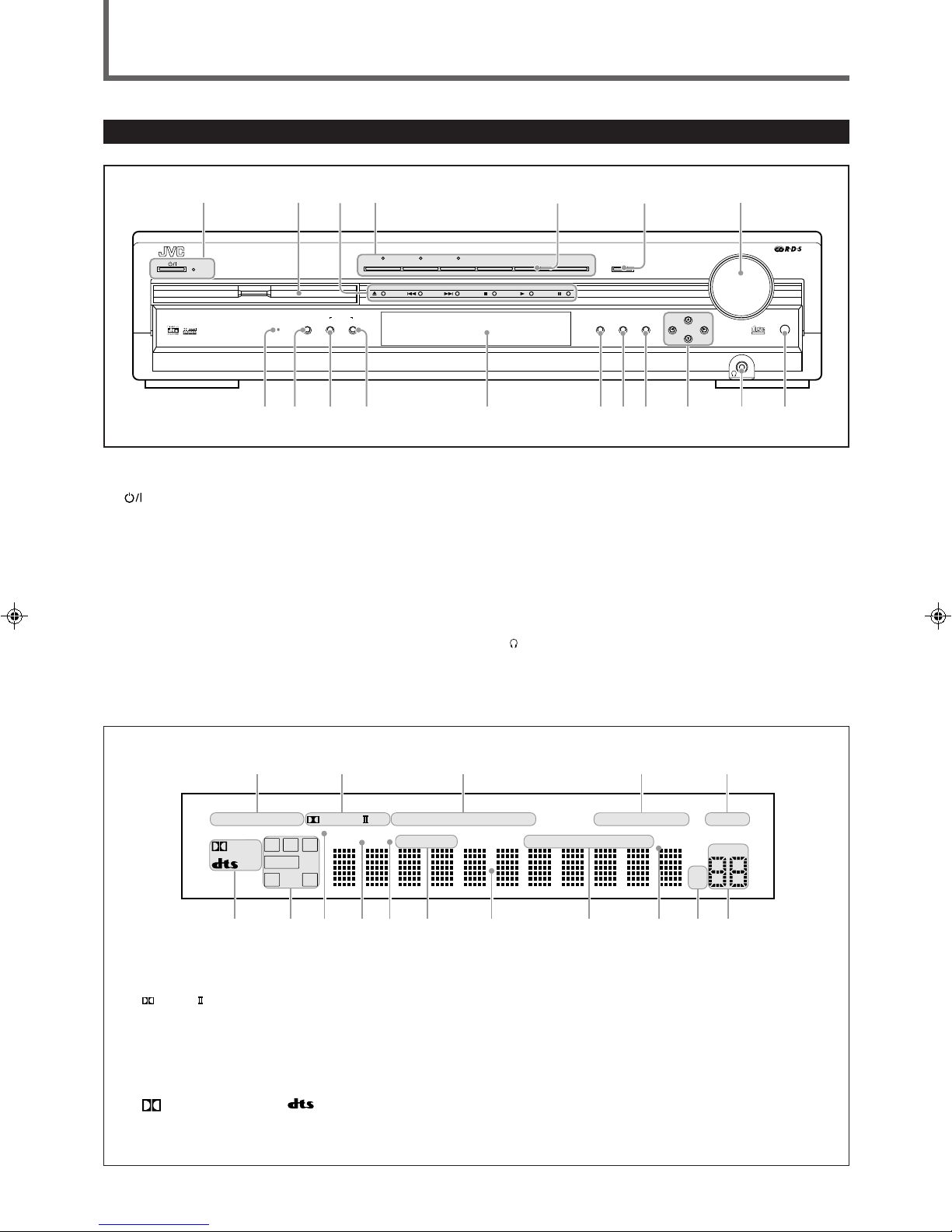
Parts Identification ...................................... 2
Front Panel ................................................................................. 2
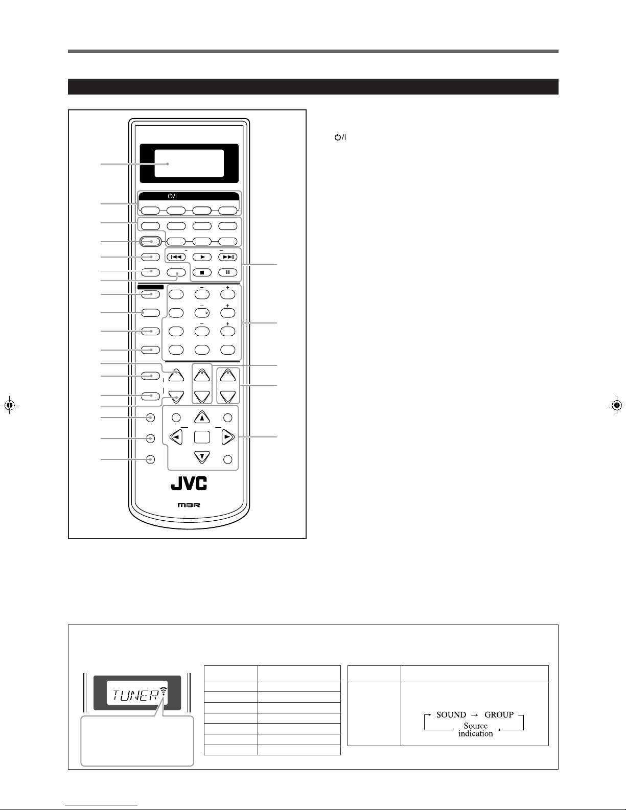
Remote Control .......................................................................... 3
Getting Started ........................................... 4
Before Installation ...................................................................... 4
Checking the Supplied Accessories ........................................... 4
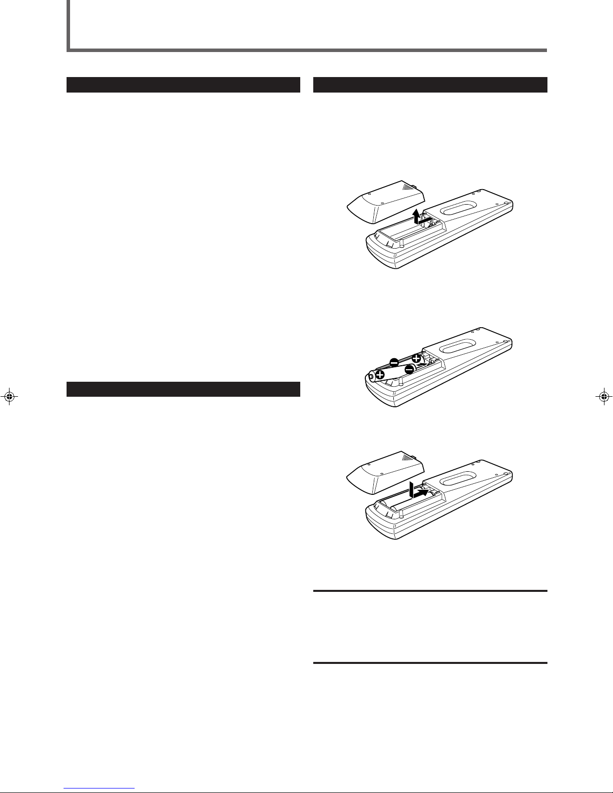
Putting Batteries in the Remote Control .................................... 4
Connecting the FM and AM Antennas ....................................... 5
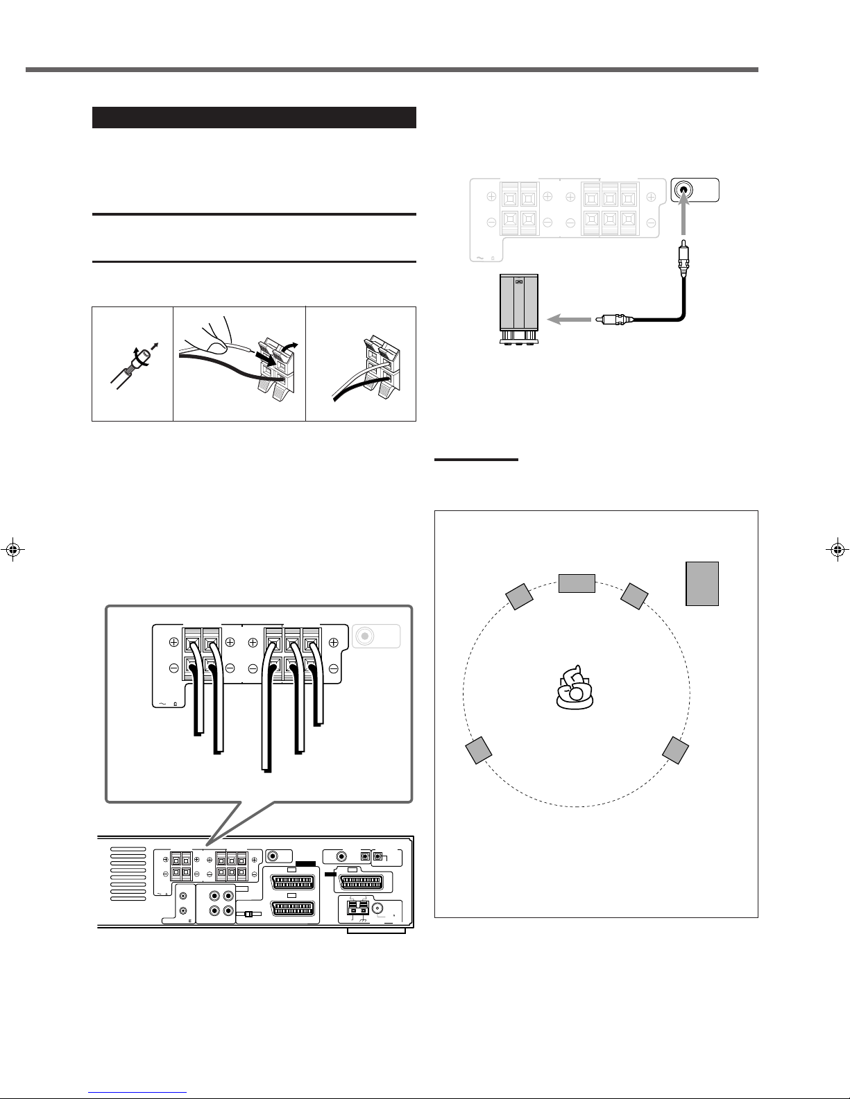
Connecting the Speakers ............................................................ 6
Connecting Audio/Video Components ....................................... 7
7About connecting cables/cords ........................................... 7
7Cassette deck/CD recoder connection ................................ 8
7Digital connection ............................................................... 8
7SCART connection ............................................................. 9
Basic Operations ....................................... 11
1 Turn On the Power ............................................................... 11
2 Select the Source to Play ..................................................... 11
3 Adjust the Volume ................................................................ 11
Turning Off the Sounds Temporarily ....................................... 12
Turning Off the Power with the Sleep Timer ........................... 12
Changing the Display Brightness ............................................. 12
Activating TV Direct ................................................................ 12
Selecting the Analog or Digital Input Mode ............................ 13
Changing the Digital Input Mode Manually ............................ 13
Attenuating the Input Signal .................................................... 14
Changing the Source Name ...................................................... 14
Activating the Recording Mode ............................................... 14
Basic DVD Player Operations ...................... 15
1 Open the Disc Tray .............................................................. 15
2 Load a Disc .......................................................................... 15
3 Start Playback ...................................................................... 15
4 Adjust the Volume ................................................................ 16
5 Activate Realistic Sound Field ............................................. 16
6 Select Surround Mode ......................................................... 16
7 Stop Playback ...................................................................... 16
8 Turn Off the Power (into Standby) ...................................... 16
Tuner Operations ....................................... 17
Tuning into Stations Manually ................................................. 17
Using Preset Tuning ................................................................. 17
Selecting the FM Reception Mode ........................................... 18
Using the RDS (Radio Data System)
to Receive FM Stations ...................................................... 19
Searching for a Program by PTY Codes .................................. 20
Switching to Broadcast Program of
Your Choice Temporarily ................................................... 21
7How the Enhanced Other Network function
actually works ................................................................... 21
7Description of the PTY codes ........................................... 22
Basic Settings........................................... 23
Operation Buttons .................................................................... 23
Operating Procedure ................................................................. 23
7Speaker information—“SUBWFR,” “FRNT SP,”
“CNTR SP,” and “REAR SP” ........................................... 24
7Speaker distance
—“FRNT D,” “CNTR D,” and “REAR D” ...................... 24
7Crossover frequency—“CROSS” ..................................... 25
7Low frequency effect attenuator—“LFE” ........................ 25
7Dynamic range compression—“D.COMP” ...................... 25
7Digital input (DIGITAL IN) terminals—“DGT” ............. 25
7Auto surround—“AUTO SR” ........................................... 26
7Auto mode—“MODE” ..................................................... 26
Sound Adjustments.................................... 27
Operation Buttons .................................................................... 27
Operating Procedure ................................................................. 27
7Front speaker output balance—“BAL”............................. 28
7Tone—“BASS” and “TREBLE” ...................................... 28
7Speaker output levels—“SUBWFR,” “CENTER,”
“REAR L,” and “REAR R” .............................................. 28
7DAP effect level—“EFFECT” .......................................... 28
Creating Realistic Sound Fields ................... 29
Activating Surround Mode ........................................................ 31
Selecting Surround Modes ........................................................ 31
Adjusting Surround Mode Using Remote Control................... 32
DVD Player Operations .............................. 33
Disc Information ....................................................................... 33
Using the On-screen Bar .......................................................... 35
Basic Operation through the On-screen Bar ............................ 36
Changing the Time Indication .................................................. 36
Locating a Desired Scene from the Disc Menu ....................... 37
Selecting a View Angle—ANGLE ........................................... 38
Changing the Languages—SUBTITLE and AUDIO ............... 39
Playing from a Specified Position on a Disc ............................ 41
7Locating a desired chapter/track—
Chapter/Track Search ....................................................... 41
7Locating a desired position—Time Search ....................... 41
7Locating a desired scene—DIGEST................................. 42
Special Picture Playback .......................................................... 43
7Frame-by-frame playback................................................. 43
7Showing continuous still pictures—STROBE .................. 43
7Playing back in slow-motion ............................................ 43
7Zooming in—ZOOM ........................................................ 43
7Changing the VFP setting—VFP ...................................... 44
Program Playback and Random Playback ............................... 45
Repeat Playback ....................................................................... 46
Additional Information for DVD AUDIO ................................ 47
Special Playback for DVD AUDIO .......................................... 47
MP3 Disc Playback .................................... 49
Basic Operations ...................................................................... 49
Operations through the MP3 CONTROL Screen .................... 50
Repeat Playback ....................................................................... 50
JPEG Disc Playback ................................... 51
Slide-show Playback ................................................................ 51
Operations through the JPEG CONTROL Screen ................... 52
Repeat Playback ....................................................................... 52
Choice Menu Operations............................. 53
Operation Buttons .................................................................... 53
Configuration of Choice Menu ................................................ 53
Operating Procedure................................................................. 54
7LANGUAGE menu .......................................................... 55
7PICTURE menu ................................................................ 55
7AUDIO menu .................................................................... 56
• Language code list ......................................................... 56
7SPK. SETTING menu ...................................................... 57
7OTHERS menu ................................................................. 58
Restricting Playback by Parental Lock .................................... 59
7Setting Parental Lock ........................................................ 59
7Changing the setting of Parental Lock ............................. 60
7Releasing Parental Lock temporarily................................ 60
• Country/Area codes list for Parental Lock ..................... 61
Glossary for DVD Player............................. 62
Operating JVC’s Audio/Video Components ........ 63
Operating Audio Components .................................................. 63
Operating Video Components .................................................. 64
Operating Other Manufacturers’ Equipment ..... 65
Changing the Preset Signal Codes ........................................... 65
Maintenance ............................................. 68
Troubleshooting ......................................... 69
Specifications ............................................ 72
EN01_10RX-DV5SL[B]2.pm5 02.8.6, 6:01 PM1

2
Parts Identification
Front Panel
See pages in the parentheses for details.
1STANDBY/ON button and STANDBY lamp (11)
2Disc tray and illumination lamp (15)
3DVD player operation buttons
0(open/close), 4(reverse skip), ¢(forward skip),
7(stop), 3(play), 8(pause)
4Source selecting buttons and lamps (11, 12)
•DVD, STB, VCR, TV, TAPE/CDR, FM/AM
5SOURCE NAME button (14)
6TV DIRECT button (12)
7MASTER VOLUME control (11, 16)
8DVD AUDIO lamp (47)
9INPUT ANALOG/DIGITAL button (13)
INPUT ATT. (attenuator) button (14)
pSURROUND ON/OFF button (16, 31)
qSURROUND MODE button (16, 31)
REC MODE button (14)
wDisplay
•For details, see “Display”below.
eSETTING button (23 –26)
rADJUST button (27, 28)
tMEMORY button (17)
yCONTROL 5/ ∞/ 2/ 3buttons (17, 18, 23 –28)
u(phones) jack (11)
iRemote sensor
Display
1Input mode indicators (13)
•ANALOG, DIGITAL AUTO
2Surround mode indicators (29, 30)
•
PRO LOGIC
, DSP
3Play mode indicators (45, 46, 50, 52)
•PROGRAM, REPEAT 1A-B, RANDOM
4RDS indicators (19)
•RDS, TA, NEWS, INFO
5INPUT ATT indicator (14)
6Sound signal indicators (13)
•
DIGITAL
(Dolby Digital), (DTS Digital Surround)
7Signal and speaker indicators (31)
•L, C, R, SUBWFR (Subwoofer), LFE (Low Frequency Effect), LS,
S, RS
8Surround indicators (31)
•AUTO SURROUND, SURROUND
9RESUME indicator (16)
0SPK. (speaker) indicator (11)
-DVD AUDIO indicators (47)
•B.S.P (Browsable Still Pictures), BONUS
=Main display
~Tuner mode indicators (17, 18)
•TUNED, STEREO, AUTO MUTING
!SLEEP indicator (12)
@Frequency unit indicators
•MHz (for FM station), kHz (for AM station)
#VOLUME indication
TV DIRECT MASTER VOLUME
DVD/SUPER VCD/VCD/CD
DVD AUDIO
INPUT ATT.
INPUT
ANALOG/DIGITAL
COMPACT
SUPER VIDEO
SETTING ADJUST MEMORY
RX-DV5R HOME CINEMA DVD-AUDIO/VIDEO CONTROL CENTER
ON/OFF
SURROUND
MODE
FM/AMTAPE/CDR
SOURCE NAME
TVVCRSTBDVD
CONTROL
STANDBY
STANDBY/ON
124 7
98wrtyuie
REC MODE
p q
35 6
AUTO
SURROUND
12 3 5
ANALOG DIGITAL AUTO
PRO LOGIC
DSP PROGRAM REPEAT RANDOM1A-B INPUT ATT
LS RSS
LFE
LCR
SUBWFR
VOLUME
RESUME SPK. B.S.P BONUS
kHz
MHz
TUNED STEREO AUTO MUTING SLEEP
687-=0~!@
#
9
DIGITAL
RDS TA NEWS INFO
4
EN01_10RX-DV5SL[B]2.pm5 02.8.6, 6:01 PM2

3
Parts Identification
Remote Control
Ex.: When you press FM/AM
When you press one of the following buttons, the remote control operation mode appears on the operation
mode display for about two hours.
This mark appears while
the remote control is
transmitting the signal to
the unit.
Button
CONTROL
Operation mode
Each time you press the button, the
operation mode changes as follows:
Button Operation mode
TV TV
TAPE TAPE
CDR CDR
FM/AM TUNER
STB STB
VCR VCR
DVD DVD
+
+
–
–
+
–
231
564
89
7
VFP
10/0 +10
100+ TV RETURN
REMOTE CONTROL RM-SRXDV5R
VCRSTB DVD
TV DIRECT
TV/VIDEO REW/(TUNING/GROUP 9/FF
REPEAT SLEEP
VCRSTB TV AUDIO
TAPETV CDR FM/AM
FM MODE STROBE
EFFECT
–TV/STB CH +
ANALOG
/DIGITAL TEST
AUDIO
INPUT
SUBTITLE
CHOICE
ENTER
TA/NEWS/INFO
PTY SEARCH
ON SCREEN
ANGLE
ZOOM
PAGE
DIGEST TOP MENU MENU
RETURN
SURR ON/OFF
SURR MODE
DIMMER
MUTING TV VOL VOLUME
–
SUBWOOFER
+
(PTY PTY9
DISPLAY
CONTROL
STANDBY/ON
CENTER
REAR·L
REAR·R
2
1
5
6
8
p
q
w
e
r
t
y
u
i
o
;
a
s
d
7
9
HOME CINEMA
DVD-AUDIO/VIDEO CONTROL CENTER
3
4
See pages in the parentheses for details.
1Operation mode display
2STANDBY/ON buttons (11, 64 –67)
•STB, VCR, TV, AUDIO
3Source selecting buttons (11, 13, 63 –67)
•TV, TAPE, CDR, FM/AM, STB, VCR, DVD
4TV DIRECT button (12)
5TV/VIDEO button (15, 64, 65)
6REPEAT button (50, 52)
7SLEEP button (12)
8CONTROL button (28, 31, 32, 47, 48)
9ANALOG/DIGITAL INPUT button (13)
pAUDIO button (39, 40)
qSUBTITLE button (39)
wDIMMER button (12)
eANGLE button (38)
•PAGE + button (48)
rZOOM button (43)
•PAGE –button (48)
tMUTING button (12)
yDIGEST button (42)
uCHOICE button (53, 54)
iON SCREEN button (35, 36, 38 –42, 45, 46)
oMulti operation buttons
•4, 3, ¢, 7, 8, REW, FF
•TUNING 9and (buttons (17)
•GROUP 9and (buttons (47)
•FM MODE button (18)
•STROBE button (43)
•TV/STB CH (channel) + and –buttons (64, 65)
;Number buttons
•For selecting preset channels (18)
•For adjusting sound (28, 32, 63)
•For operating audio/video components (63 –67)
•SURR (surround) ON/OFF button (16, 31)
•SURR (surround) MODE button (16, 31)
•VFP button (44)
•TV RETURN button (64)
aTV VOL (volume) + and –buttons (64, 65)
sVOLUME + and –buttons (11, 16)
dMenu operation buttons
•TOP MENU button (37) •MENU button (37)
•RETURN button (37) •ENTER button
•Cursor 5/∞/3/2buttons
RDS operation buttons
•TA/NEWS/INFO button (21) •PTY SEARCH button (20)
•PTY 9and (buttons (20) •DISPLAY button (19)
EN01_10RX-DV5SL[B]2.pm5 02.8.6, 6:01 PM3

4
Getting Started
Putting Batteries in the Remote Control
Before using the remote control, put two supplied batteries first.
•When using the remote control, aim the remote control directly at
the remote sensor on the unit.
1
On the back of the remote control, remove the
battery cover.
2
Insert batteries. Make sure to match the polarity:
(+) to (+) and (–) to (–).
3
Replace the cover.
If the range or effectiveness of the remote control decreases, replace
the batteries. Use two R6P(SUM-3)/AA(15F) type dry-cell batteries.
CAUTION:
Follow these precautions to avoid leaking or cracking cells:
•Place batteries in the remote control so they match the polarity:
(+) to (+) and (–) to (–).
•Use the correct type of batteries. Batteries that look similar may
differ in voltage.
•Always replace both batteries at the same time.
•Do not expose batteries to heat or flame.
Before Installation
General Precautions
•DO NOT insert any metal object into the unit.
•DO NOT disassemble the unit or remove screws, covers, or
cabinet.
•DO NOT expose the unit to rain or moisture.
Locations
•Install the unit in a location that is level and protected from
moisture.
•The temperature around the unit must be between 5˚C and 35˚C.
•Make sure there is good ventilation around the unit. Poor
ventilation could cause overheating and damage the unit.
Handling the unit
•DO NOT touch the power cord with wet hands.
•DO NOT pull on the power cord to unplug it. When unplugging
the cord, always grasp the plug so as not to damage the cord.
•Keep the power cord away from the connecting cords and the
antenna. The power cord may cause noise or screen interference. It
is recommended to use a coaxial cable for antenna connection,
since it is well-shielded against interference.
•When a power failure occurs, or when you unplug the power cord,
the preset settings such as preset FM or AM channels and sound
adjustments may be erased in a few days.
Checking the Supplied Accessories
Check to be sure you have all of the following supplied accessories.
The number in the parentheses indicates the quantity of the pieces
supplied.
•Remote Control (1)
•Batteries (2)
•AM Loop Antenna (1)
•FM Antenna (1)
If anything is missing, contact your dealer immediately.
EN01_10RX-DV5SL[B]2.pm5 02.8.6, 6:01 PM4

5
Getting Started
Connecting the FM and AM Antennas
AM loop antenna
(supplied)
If AM reception is poor,
connect an outdoor single
vinyl-covered wire (not
supplied).
FM antenna (supplied)
If FM reception is poor, connect
outdoor FM antenna (not supplied).
Snap the tabs on the loop into
the slots of the base to
assemble the AM loop antenna.
AM LOOP
FM 75
COAXIAL
AM EXT
SUB-
WOOFER
OUT DIGITAL 1
(STB)
DIGITAL 2
(TV)
PCM/STREAM
FRONT
SPEAKERS
REAR
SPEAKERS
CENTER
SPEAKER
DIGITAL IN
ANTENNA
TAPE / CDR AUDIO
AV IN/OUT
CAUTION:
SPEAKER
IMPEDANCE
816
AV COMPU LINK-
RIGHT
LEFT
IN
(PLAY)
OUT
(REC)
DIGITAL OUT
RGB YC
STB
TV
VCR
AV IN
RIGHT RIGHT LEFTLEFT
FM 75
COAXIAL
ANTENNA
AM LOOP
FM 75
COAXIAL
AM
EXT
B
FM 75
COAXIAL
123
1
2
Rear panel of the unit
AM antenna connection
Connect the AM loop antenna supplied to the AM LOOP
terminals.
1
Remove the insulation if the AM loop antenna
wire is covered with vinyl.
2
Press and hold the clamp of the terminal (1),
then insert the wire (2).
3
Release the clamp.
Turn the loop until you have the best reception.
•If the reception is poor, connect an outdoor single vinyl-
covered wire (not supplied) to the AM EXT terminal. Keep the
AM loop antenna connected.
FM antenna connection
Connect the FM antenna supplied to the FM 75 ΩCOAXIAL
terminal as temporary measure.
Extend the supplied FM antenna horizontally.
•If the reception is poor, connect an outdoor FM antenna (not
supplied). Before attaching a 75 Ωantenna with a coaxial type
connector (IEC or DIN 45325), disconnect the supplied FM
antenna.
Note:
•Make sure the antenna conductors do not touch any other
terminals, connecting cords and power cord. This could cause poor
reception.
EN01_10RX-DV5SL[B]2.pm5 02.8.6, 6:01 PM5

6
AM LOOP
FM 75
COAXIAL
AM EXT
SUB-
WOOFER
OUT DIGITAL 1
(STB)
DIGITAL 2
(TV)
PCM/STREAM
FRONT
SPEAKERS
REAR
SPEAKERS
CENTER
SPEAKER
DIGITAL IN
ANTENNA
TAPE / CDR AUDIO
AV IN/OUT
CAUTION:
SPEAKER
IMPEDANCE
816
AV COMPU LINK-
RIGHT
LEFT
IN
(PLAY)
OUT
(REC)
DIGITAL OUT
RGB YC
STB
TV
VCR
AV IN
FRONT
SPEAKERS
REAR
SPEAKERS
CENTER
SPEAKER
CAUTION:
SPEAKER
IMPEDANCE
816
SUB-
WOOFER
OUT
RIGHT LEFT RIGHT LEFT
Connecting the Speakers
After connecting the front, center and rear speakers, and/or a
subwoofer, set the speaker setting information properly to obtain the
best possible Surround effect. For details, see page 24.
CAUTIONS:
•Use speakers with the SPEAKER IMPEDANCE indicated by the
speaker terminals (8 –16 Ω).
•DO NOT connect more than one speaker to one speaker terminal.
Connecting the front, center, and rear speakers
For each speaker, connect the (+) and (–) terminals on the rear panel
to the (+) and (–) terminals marked on the speakers respectively.
1
Cut, twist and remove the insulation at the end of
each speaker cord (not supplied).
2
Press and hold the clamp of the speaker terminal
(1), then insert the speaker cord (2).
3
Release the clamp.
1
2
123
Connecting the subwoofer speaker
By connecting a subwoofer, you can enhance the bass or reproduce
the original LFE signals recorded in the digital software.
Connect the input jack of a powered subwoofer to the SUB-
WOOFER OUT jack on the rear panel, using a cable with RCA pin
plugs (not supplied).
•Refer also to the manual supplied with your subwoofer.
Note:
•You can place a subwoofer wherever you like since bass sound is
non-directional. Normally place it in front of you.
To left front speaker
To center speaker
To right front
speaker
To left rear
speaker
To right rear
speaker
SUB-
WOOFER
OUT
FRONT
SPEAKERS
REAR
SPEAKERS
CENTER
SPEAKER
CAUTION:
SPEAKER
IMPEDANCE
816
RIGHT LEFT RIGHT LEFT
Speaker Layout Diagram
Center speaker
Left rear
speaker
Right rear
speaker
Left front
speaker
Right front
speaker
Subwoofer
To obtain the best possible sound from this system, place all the
speakers except the subwoofer at the same distance from the
listening position with each speaker’s front faced toward the
listener.
Then, change the subwoofer and speaker settings to fit your
listening conditions (see page 24).
Getting Started
Powered subwoofer
(example)
EN01_10RX-DV5SL[B]2.pm5 02.8.6, 6:01 PM6

7
Getting Started
Connecting Audio/Video Components
Turn off all the components and the unit before connection.
TV connection
■About connecting cables/cords
For SCART connections
The SCART cable is not supplied with this unit.
Use the cables supplied with the other components or
purchase them at your dealer.
For audio connections
Connect the external components to this unit with the audio cords.
Use the cord supplied with the other components or purchase them at your dealer.
•When the unit is shipped from the factory, the DIGITAL IN
terminals are set for use with the following components:
–DIGITAL 1 (coaxial): For STB
–DIGITAL 2 (optical): For TV
•If you connect CDR, change the digital input (DIGITAL IN)
terminal setting (see “Digital input (DIGITAL IN) terminals”on
page 25) and the source name (see “Changing the Source
Name”on page 14) correctly.
•Select the digital input mode correctly (see “Selecting the
Analog or Digital Input Mode”on page 13).
Audio cord (not supplied)
Optical digital cord (not supplied)
Digital coaxial cord (not supplied)
A
B
C
White
Red
If you connect a sound-enhancing device such as a graphic
equalizer between the source components and this unit, the sound
output through this unit may be distorted.
For an analogue decoder
To watch or record a scrambled program on your VCR, connect the
analogue decoder to your VCR and select the scrambled channel
on your VCR.
If there is not an appropriate terminal for the decoder on your VCR,
connect the decoder to your TV.
Refer also to the manuals supplied with these equipments.
For recording pictures from STB
When you connect an STB and a VCR directly with a SCART
cable, you can enjoy recording the pictures from the STB onto VCR
without using menu screens of STB. For details, refer also to the
manuals supplied with the STB.
For digital sounds
To enjoy the digital sounds, use both the SCART cable connection
and the digital connection (see page 8).
SCART cable (not supplied)
EN01_10RX-DV5SL[B]2.pm5 02.8.6, 6:01 PM7

8
Getting Started
■Digital connection
Before connecting an
optical digital cord,
unplug the protective
plug.
AM LOOP
FM 75
COAXIAL
AM EXT
SUB-
WOOFER
OUT
DIGITAL 1
(STB)
DIGITAL 2
(TV)
PCM/STREAM
REAR
SPEAKERS
DIGITAL IN
ANTENNA
AUDIO
AV IN/OUT
DIGITAL OUT
RGB YC
STB
TV
VCR
AV IN
LEFT
DIGITAL 1
(STB)
DIGITAL 2
(TV)
DIGITAL IN
A
B
DIGITAL
OUT
DIGITAL
OUT
DIGITAL
IN
B
PCM/STREAM
DIGITAL OUT
TV
STB (Set Top Box)
CD recorder
CD recorder
AM LOOP
FM 75
COAXIAL
AM EXT
SUB-
WOOFER
OUT DIGITAL 1
(STB)
DIGITAL 2
(TV)
PCM/STREAM
FRONT
SPEAKERS
REAR
SPEAKERS
CENTER
SPEAKER
DIGITAL IN
ANTENNA
TAPE / CDR AUDIO
AV IN/OUT
CAUTION:
SPEAKER
IMPEDANCE
816
AV COMPU LINK-
RIGHT
LEFT
IN
(PLAY)
OUT
(REC)
DIGITAL OUT
RGB YC
STB
TV
VCR
AV IN
RIGHT LEFTRIGHT LEFT
LEFT
RIGHT
AUDIO
OUT IN
C
C
TAPE / CDR
RIGHT
LEFT
IN
(PLAY)
OUT
(REC)
Cassette deck
CD recorder
White
Red
Red
White
White
Red
Red
White
Turn off all the components and the unit before connection.
■Cassette deck/CD recorder connection
Illustrations of the input/output terminals are typical examples.
When you connect other components, refer also to their
manuals since the terminal names actually printed on the rear
vary among the components.
EN01_10RX-DV5SL[B]2.pm5 02.8.6, 6:01 PM8

9
Turn off all the components and the unit before connection. Illustrations of the input/output terminals below are typical
examples. When you connect other components, refer also to
their manuals since the terminal names actually printed on the
rear vary among the components.
Getting Started
DO NOT connect a TV through a VCR or a TV with a built-in
VCR; otherwise, the picture may be distorted.
■SCART connection
*1 The signals input from a SCART terminal cannot be output
through the same SCART terminal.
*2 The video format of the output video signals are consistent
with that of the input video signals. For example, if S-video
signals are input to this unit, no signals other than S-video
signals can be output from this unit.
Refer to the manuals supplied with the video components to
check the setting of the input/output video signals.
*3 The signals for T-V LINK function are always going through
the unit.
SCART Terminal Specifications
TV VCR STB
AUDIO L/R 䡬䡬䡬
IN Composite 䡬䡬䡬
VIDEO S-video −䡬䡬
RGB −䡬䡬
AUDIO L/R 䡬*1䡬*1
OUT Composite 䡬*1*2䡬*1*2
VIDEO S-video 䡬*2−
RGB 䡬*2−
T-V LINK 䡬*3䡬*3䡬*3
Setting the RGB/YC selector
Set the RGB/YC selector as follows while the unit is
turned off:
•When the TV is compatible with RGB signal, set to “RGB.”
•When the TV is compatible with S-video signal, set to “YC.”
•When the TV is compatible with composite video signal only, set
to “RGB.”
Note:
•If you change the RGB/YC selector setting while the unit is turned
on, this setting will not take effect until the unit is turned off.
RGB YC
AM LOOP
FM 75
COAXIAL
AM EXT
SUB-
WOOFER
OUT DIGITAL 1
(STB)
DIGITAL 2
(TV)
PCM/STREAM
FRONT
SPEAKERS
REAR
SPEAKERS
CENTER
SPEAKER
DIGITAL IN
ANTENNA
TAPE / CDR AUDIO
AV IN/OUT
CAUTION:
SPEAKER
IMPEDANCE
816
AV COMPU LINK-
RIGHT
LEFT
IN
(PLAY)
OUT
(REC)
DIGITAL OUT
RGB YC
STB
TV
VCR
AV IN
RIGHT LEFTRIGHT LEFT
RGB
AV IN/OUT
YC
STB
TV
VCR
AV IN
RGB/YC selector
EN01_10RX-DV5SL[B]2.pm5 02.8.6, 6:01 PM9

10
Now, you can plug the power cord of the unit into the AC outlet.
CAUTIONS:
•Do not touch the power cord with wet hands.
•Do not pull on the power cord to unplug the cord. When unplugging
the cord, always grasp the plug so as not to damage the cord.
Notes:
•Keep the power cord away from the connecting cords and the
antenna cables. The power cord may cause noise or screen
interference.
•The preset settings such as preset channels and sound adjustment
may be erased in a few days in the following cases:
–When you unplug the power cord.
–When a power failure occurs.
Getting Started
When the TV is equipped with the plural SCART terminals,
refer to the manual supplied with the TV to check the
available video signals for each terminal, then connect
SCART cable correctly.
For TV and video format
This unit cannot convert the video signals (S-video or
Composite). When the video signal of one video component
is different from that of the other (for example, one is
S-video, the other is Composite), you may not see the
pictures appropriately. In this case, unify the video signals of
all the video components into S-video or Composite, or you
need to switch the video signal of TV each time you change
the source.
•You can use T-V LINK function if you connect the T-V LINK
compatible TV and VCR to this unit with a fully wired
SCART cables. For details on T-V LINK, refer also to the
manuals supplied with the TV and the VCR.
•Connect SCART cable to EXT-2 terminal on your JVC's
T-V LINK compatible TV for T-V LINK function.
•Some TV, VCR, and STB support this type of data
communication. For complete details, refer also to the
manuals supplied with these equipments.
For T-V LINK
TV
VCR
STB (Set Top Box)
EN01_10RX-DV5SL[B]2.pm5 02.8.6, 6:01 PM10

11
1
Turn On the Power
Press STANDBY/ON on the front panel or
STANDBY/ON AUDIO on the remote control.
The STANDBY lamp goes off and the illumination lamp lights up.
The current source name appears on the display.
•If the built-in DVD player is the current source, “READING”
appears while the unit is detecting the type of the loaded disc
(see page 33).
–Playback starts automatically when you load some DVD
VIDEO.
–“NO DISC”appears on the display when no disc is loaded.
To turn off the power (into standby)
Press STANDBY/ON on the front panel or
STANDBY/ON AUDIO on the remote control again.
The illumination lamp goes off and the
STANDBY lamp lights up.
Note:
•A small amount of the power is consumed even in standby mode.
To turn off the power completely, unplug the AC power cord.
2
Select the Source to Play
Press one of the source selecting buttons.
DVD : Select the built-in DVD player.
STB* : Select the STB.
VCR : Select the VCR.
TV* : Select the TV tuner.
TAPE/CDR* : Select the cassette deck or the CD recorder (front
panel ONLY).
TAPE : Select the cassette deck (remote control ONLY**).
CDR* : Select the CD recorder (remote control ONLY**).
FM/AM : Select an FM or AM broadcast.
When you press one of the buttons listed above, the remote control
operation mode appears on the operation mode display for about 2
hours.
STANDBY
STANDBY/ON
VCRSTB TV AUDIO
STANDBY/ON
On the front panel From the remote control
Basic Operations
STANDBY
STANDBY/ON
On the front panel
From the remote control
FM/AMTAPE/CDR
SOURCE NAME
TVVCRSTBDVD
VCRSTB DVD
TV DIRECT
TAPETV CDR FM/AM
Notes:
*
Register the digital input terminal setting (see “Digital input
(DIGITAL IN) terminals”on page 25) and digital input mode setting
correctly (see “Selecting the Analog or Digital Input Mode”on page
13). Source name and “DIGITAL”will be shown on the display when
you select the source.
**
When the source name is not assigned correctly, these buttons
cannot work (see “Changing the Source Name”on page 14).
DVD AUDIO/VIDEO RECEIVER
Ex. : When you press DVD
3
Adjust the Volume
On the front panel:
To increase the volume,
turn MASTER VOLUME clockwise.
To decrease the volume,
turn MASTER VOLUME counterclockwise.
From the remote control:
To increase the volume,
press and hold VOLUME +.
To decrease the volume,
press and hold VOLUME –.
CAUTION:
Always set the volume to the minimum before starting any sources. If
the volume is set at a high level, the sudden blast of sound energy
can permanently damage your hearing and/or ruin your speakers.
Notes:
•The volume level can be adjusted within the range of “0”(minimum)
to “50”(maximum).
•When DVD is selected as the source with your TV turned on, the
volume level indication appears on the TV.
Listening with headphones
Connect a pair of headphones to the (phones) jack on the
front panel. This cancels the Surround mode currently
selected, deactivates speakers, and activates the
HEADPHONE mode.
The SPK. indicator goes off from the display.
•Disconnecting a pair of headphones from the (phones) jack
cancels the HEADPHONE mode and activates speakers.
HEADPHONE mode
When using the headphones, the following signals are output
regardless of your speaker setting:
—For 2-channel sources, the front left and right channel signals
are output directly from the left and right headphones.
—For multichannel sources, the front left and right, center and
rear channel signals are down-mixed and then output from the
headphones without missing bass element.
—For DVD AUDIO ONLY: When the multichannel track
cannot be down-mixed, only signals of the front left and right
channel are output.
CAUTION:
Be sure to turn down the volume:
•Before connecting or putting on headphones, as high volume can
damage both the headphones and your hearing.
•Before removing headphones, as high volume may output from the
speakers.
MASTER VOLUME
+
–
VOLUME
EN11-14RX-DV5SL[B]2.pm5 02.8.6, 6:01 PM11

12
Turning Off the Sounds Temporarily
Press MUTING to mute the sound.
“MUTING”appears on the display and the volume turns off (the
VOLUME indication goes off).
•When DVD is selected as the source with your TV turned on,
“VOLUME –” appears on the TV.
To restore the sound
Press MUTING again.
•Pressing VOLUME + or –on the remote control (or turn
MASTER VOLUME on the front panel) also restores the sound.
Turning Off the Power
with the Sleep Timer
Press SLEEP repeatedly.
The SLEEP indicator lights up on the display.
•Each time you press the button, the shut-off time changes as
follows:
When the shut-off time comes
The unit is turned off automatically.
To check or change the remaining time until the shut-off time
Press SLEEP once.
The remaining time (in minutes) until the shut-off time appears.
•To change the shut-off time, press SLEEP repeatedly.
To cancel the Sleep Timer
Press SLEEP repeatedly until “SLEEP 0”appears on the display.
(The SLEEP indicator goes off.)
•Turning off the unit also cancels the Sleep Timer.
Note:
•If Sleep Timer and Auto Standby (see page 58) are used at a time,
one with the early shut-off time will turn off the unit.
Changing the Display Brightness
Press DIMMER to dim the display.
•Each time you press the button, the display and
illumination lamp dim and brighten alternately.
Activating TV Direct
You can use this unit as a DVD player and an AV selector while the
unit is not turned on. When this function is activated, the pictures
and sounds go from the video components to the TV through this
unit. In this case, you can use the video components and the TV as if
they were connected directly—TV Direct.
•This function takes effect only when the video components and
TV are connected to this unit with SCART cables.
•This function takes effect for the following sources—DVD, STB,
and VCR.
•This unit can be automatically turned on or off, and/or select the
source automatically when you set the Auto Function mode to
“AUTO1”or “AUTO2.”For details, see “Auto mode”on page 26.
To activate (or deactivate) TV Direct, follow the procedure below:
1
Press TV DIRECT.
All the indications disappear (except when DVD is selected as
the source), then the source lamp currently selected lights up.
2
Turn on the video component and TV.
3
Press one of the source selecting buttons—DVD,
STB, or VCR.
The lamp corresponding to the
selected source lights up.
To cancel TV Direct and turn off the unit, press
STANDBY/ON (or STANDBY/ON AUDIO on the remote
control).
The unit is turned off and the STANDBY lamp lights up.
To cancel TV Direct and turn on the unit, press TV DIRECT.
Notes:
•When TV Direct is activated, you cannot enjoy any of the sound
effects this unit produces, and cannot use the speakers connected
to this unit.
•You can use T-V LINK function between TV and VCR while the TV
Direct is activated.
Basic Operations
DIMMER
From the remote control ONLYFrom the remote control ONLY
DIGITAL AUTO
SPK.
L R
From the remote control ONLY
SLEEP
DIGITAL AUTO
VOLUME
SPK. SLEEP
10 20 30 60
120 901500 (off)
LR
SLEEP indicator
TV DIRECT
VCRSTB DVD
TV DIRECT
On the front panel From the remote control
MUTING
VCRSTBDVD
Ex. : When DVD is selected.
EN11-14RX-DV5SL[B]2.pm5 02.8.6, 6:01 PM12

13
Selecting the Analog or Digital Input Mode
When you have connected digital source components using both the
analog connection and the digital connection methods (see pages 7 to
10), you can select the input mode.
•Before selecting the digital input mode, register the digital input
terminal setting correctly (see “Digital input (DIGITAL IN)
terminals”on page 25).
1
Press one of the source selecting buttons (STB,
TV, or CDR) for which you want to change the
input mode.
Note:
•
You cannot change the input mode when selecting DVD as the
source. Digital input is always used for the built-in DVD player.
2
Press INPUT ANALOG/DIGITAL (INPUT ATT.)
on the front panel or ANALOG/DIGITAL INPUT
on the remote control.
The current input mode appears on the display.
•Each time you press the button, the input mode alternates
between the analog input (“ANALOG”*) and the digital input
(“DGTL AUTO”).
*“ANALOG”is the initial setting except for the built-in DVD
player.
DGTL AUTO : Select this for the digital input mode.
The DIGITAL AUTO indicator lights up.
The unit automatically detects the incoming
signal format, then the sound signal indicator
for the detected signal—
DIGITAL
or
lights up; otherwise, no sound signal indicators
light up.
ANALOG : Select this for the analog input mode.
The ANALOG indicator lights up.
Basic Operations
Changing the Digital Input Mode Manually
If the following symptoms occur while Dolby Digital or DTS
Digital Surround software is played back, you can change the digital
input mode:
•Sound does not come out at the beginning of playback.
•Noise comes out while searching for or skipping chapters or
tracks.
Press CONTROL 3(or 2) to select “DGTL D.D.”
or “DGTL DTS”while “DGTL AUTO”still remains
on the display.
•Each time you press the button, the digital input mode changes as
follows:
DGTL AUTO : Normally select this.
The DIGITAL AUTO indicator lights up.
The unit automatically detects the incoming
signal format, then the sound signal indicator
for the detected signal lights up.
DGTL D.D. : Select this for playing back software encoded
with Dolby Digital.
The
DIGITAL
indicator lights up*.
DGTL DTS : Select this for playing back software encoded
with DTS Digital Surround.
The indicator lights up*.
* These indicators flash when no signal or the signal without the
proper format is played back.
When DVD is selected as the source, you can also
change the digital input mode by pressing
ANALOG/DIGITAL INPUT repeatedly on the remote
control.
Notes:
•When “DGTL AUTO”cannot recognize the incoming signals, no
sound signal indicators light up on the display.
•When you turn off the unit or select another source, “DGTL DTS”
and “DGTL D.D.”are canceled.
The digital input mode is automatically reset to “DGTL AUTO.”
FM/AMTAPE/CDR
SOURCE NAME
TVVCRSTBDVD
On the front panel
From the remote control
On the front panel
CONTROL
DIGITAL AUTO
VOLUME
DGTL AUTO DGTL D.D.
DGTL DTS
LR
On the front panel From the remote control
INPUT ATT.
INPUT
ANALOG/DIGITAL
ANALOG DIGITAL AUTO
VOLUME
SPK.
DGTL AUTO ANALOG
LR
ANALOG/DIGITAL AUTO indicator
VCRSTB DVD
TV DIRECT
TAPETV CDR FM/AM
ANALOG
/DIGITAL
INPUT
ANALOG
/DIGITAL
INPUT
EN11-14RX-DV5SL[B]2.pm5 02.8.6, 6:01 PM13

14
Attenuating the Input Signal
When the input level of the analog source is too high, the sounds
will be distorted. If this happens, you need to attenuate the input
signal level to prevent the sound distortion.
•You have to make this adjustment for each analog source.
Press and hold INPUT ATT. (INPUT ANALOG/
DIGITAL) until the INPUT ATT indicator lights up
on the display.
•Each time you press and hold the button, the Input Attenuator
turns on (“ATT ON”) or off (“ATT NORMAL”*).
*“ATT NORMAL”is the initial setting.
ATT NORMAL : Normally select this. The analog sound is not
attenuated.
ATT ON : Select this when the analog sound is
distorted.
INPUT ATT.
INPUT
ANALOG/DIGITAL
On the front panel ONLY
Basic Operations
TAPE/CDR
SOURCE NAME
Changing the Source Name
When you connect an CD recorder to the TAPE/CDR jacks on the
rear panel, change the source name which will be shown on the
display.
Ex. : When changing the source name from “TAPE”to “CDR”
1
Press TAPE/CDR (SOURCE NAME) to select as
the source.
2
Press and hold SOURCE NAME (TAPE/CDR)
until “ASSGN. CDR”appears on the display.
To change the source name to “TAPE”
Press and hold SOURCE NAME (TAPE/CDR) until “ASSGN.
TAPE”appears on the display in step
2
.
Note:
•Without changing the source name, you can still use the connected
components. However, there may be some inconveniences:
–The unexpected source name will appear on the display when
you press TAPE/CDR (SOURCE NAME) on the front panel.
–The CDR or TAPE button on the remote control cannot work for
selecting the source.
–You cannot use the digital input (see page 8) for the CD recorder.
Activating the Recording Mode
When you play back the multichannel sources, Recording mode
enables you to record the sounds without missing surround elements
by down-mixing the center and rear channel signals into the front
channel signals.
•For DVD AUDIO ONLY: When the multichannel track cannot be
down-mixed, this function does not take effect.
•When the multichannel software is played back with Recording
mode activated, the sounds are down-mixed and come out through
the front speakers only.
Press and hold REC MODE (SURROUND MODE)
until “RECMODE ON”appears on the display.
•Each time you press and hold the button, Recording mode is
activated (“RECMODE ON”) and deactivated (“RECMODE
OFF*”) alternately.
*“RECMODE OFF”is the initial setting.
RECMODE OFF : Normally select this. The down-mixing is
canceled.
RECMODE ON : Select this for recording the down-mixed
sounds.
When recording with VCR:
You can record the picture on your video tape without the volume
level indication when Recording mode is activated.
•When you do not want to record the on-screen guide icons, see
page 58.
•The choice menu and on-screen bar are always recorded when
they appear on the TV.
CAUTION:
When the front speakers are small, the output sound may be distorted
by Recording mode. In this case, decrease the volume until the sound
distortion diminishes.
Notes:
•When you turn off the unit or select another source, Recording
mode is canceled (“RECMODE OFF”).
•Sound adjustments (see pages 27 and 28) and Surround modes
(see pages 29 to 32) do not affect the recording.
•The following buttons do not work while Recording mode is
activated (“RECMODE ON”):
–SETTING and ADJUST on the front panel.
–SURROUND ON/OFF and SURROUND MODE on the front
panel.
–Number buttons for adjusting sound on the remote control.
On the front panel ONLY
ANALOG INPUT ATT
VOLUME
ATT NORMAL ATT ON
L R
INPUT ATT indicator
ANALOG
VOLUME
ASSGN. TAPE ASSGN. CDR
LR
On the front panel ONLY
ON/OFF
SURROUND
MODE
REC MODE
EN11-14RX-DV5SL[B]2.pm5 02.8.6, 6:01 PM14

15
By pressing the following buttons, you can pause, advance, or reverse
playback, and locate the beginning of the title, chapter, or track.
To stop playback temporarily
Press 8.
•Pressing 3starts playback again.
To move back the playback position by 10 seconds
(for DVD VIDEO only)
Press 3during DVD VIDEO playback.
The unit moves the playback position about 10 seconds before the
current position, then resumes playback.
To advance or reverse playback rapidly
Press and hold ¢or 4.
While you are pressing and holding ¢(or 4), the unit advances
(or reverses: for DVD VIDEO and audio CD) playback 5 times as
fast as the normal speed. When you press and hold ¢(or 4)
further, the playback speed changes up to 20 times as fast as the
normal speed.
•Releasing the button resumes the normal playback.
To locate the beginning of the chapter or track
Press ¢or 4.
Press ¢(or 4) to locate the beginning of the next (current or
previous) chapter or track.
To locate the chapter or track using the number buttons
Press the number buttons (1–10, +10) to select the number of the
desired chapter or track.
Ex. : To select 3, press 3.
To select 11, press +10, then 1.
To select 20, press +10, then 10.
Basic DVD Player Operations
About indication on the display while playing back a disc
While you are playing back a disc, the playback information
appears on the display as follows:
Ex. : When DVD VIDEO is loaded
Ex. : When audio CD is loaded
Track number Elapsed playing time
SPK.
DIGITAL AUTO
VOLUME
PRO LOGIC
LR
SUBWFR
From the remote control ONLY
231
564
89
7
10/0 +10
100+
EFFECT
TEST
SURR ON/OFF
SURR MODE
–
SUBWOOFER
+
CENTER
REAR·L
REAR·R
DIGITAL AUTO
VOLUME
DIGITAL
AUTO
SURROUND
SPK.
LFE
LS RS
LCR
SUBWFR
Chapter number Elapsed playing time
On the front panel
From the remote control
For details about DVD player operations, see pages 33 to 48.
•You can also play back MP3 and JPEG files. See pages 49 to
52.
•When using the remote
control, press DVD to change
the remote control operation
mode to the DVD player
operation.
DVD AUDIO/VIDEO RECEIVER
1
Open the Disc Tray
Before turning on the unit, turn on your TV and select the correct
video input (see the manual supplied with your TV).
•When you use a JVC’s TV, you can turn on your TV by pressing
STANDBY/ON TV on the remote control and select the
video input by pressing TV/VIDEO. (If your TV is not a JVC’s,
see “Operating Other Manufacturers’Equipment”on page 65.)
•For changing the OSD messages—the information on the TV
—into the desired language, see pages 53 and 55.
Press 0.
The unit is turned on and the disc tray opens.
The STANDBY lamp goes off and the illumination lamp lights up.
•When a disc is already loaded, pressing 3turns on the unit and
starts playing back the loaded disc.
2
Load a Disc
Place a disc correctly with its label side up.
On the front panel ONLY
CORRECT
INCORRECT
3
Start Playback
Press 3.
The disc tray closes and the unit starts playing back the loaded disc.
•You can also close the disc tray by pressing 0on the front panel.
On the front panel From the remote control
TUNING/GROUP
REW/(TUNING/GROUP 9/FF
FM MODE STROBE
–TV/STB CH +
RX-DV5R HOME CINEMA DVD-AUDIO/VIDEO CONTROL CENT
F
TAPE/CDR
SOURCE NAME
TV
VCR
STB
DVD
STANDBY
STANDBY/ON
DVD AUDIO
INPUT ATT.
INPUT
ANALOG/DIGITAL
DIGITAL
SURROUND
ON/OFF
SURROUND
MODE
EN15-22RX-DV5SL[B]2.pm5 02.8.6, 6:01 PM15

16
Basic DVD Player Operations
4
Adjust the Volume
For details, see “Basic Operations”on page 11.
5
Activate Realistic Sound Field
You can activate Surround mode for creating realistic sound fields.
•You can activate Surround mode automatically when the digital
multichannel source (Dolby Digital or DTS Digital Surround
software) or 2-channel matrix source (Dolby Surround software) is
played back—Auto Surround (see page 26).
When you activate or deactivate Surround mode manually, do the
following procedures:
On the front panel:
Press SURROUND ON/OFF.
From the remote control:
1) Press CONTROL repeatedly so that
“SOUND”appears on the operation
mode display.
2) Press SURR ON/OFF.
•Each time you press SURROUND ON/OFF on the front panel or
SURR ON/OFF on the remote control, Surround mode is activated
and deactivated alternately.
6
Select Surround Mode
When the PRO LOGIC II or DSP indicator is lit, you can select
various Surround modes (see page 31).
Press SURROUND MODE (REC MODE) on the
front panel or SURR MODE on the remote control.
•
When you enjoy digital multichannel source such as Dolby Digital
or DTS Digital Surround software, you cannot change Surround
mode. When you enjoy Dolby Digital or DTS Digital Surround 2-
channel including 2-channel matrix source such as Dolby Surround
software, you can select Surround mode from between PRO
LOGIC II MOVIE and PRO LOGIC II MUSIC (see page 31).
7
Stop Playback
Press 7.
Playback stops.
The unit memorizes the point where you stop playback and the
RESUME indicator lights up on the display (except when an audio
CD is loaded).
While the RESUME indicator is lit on the display, you can start
playback from the memorized point by pressing 3—Resume play.
About Resume play
This unit can memorize the point when you operate the following
procedures:
•Pressing 7during playback—Pressing 3starts Resume play
•Changing the source—Pressing DVD or 3starts Resume play
•Turning off the unit (including Sleep Timer)
—Pressing 3starts Resume play
Once you start Resume play, the RESUME indicator goes off
(the unit clears the memorized point).
The unit also clears the memorized point when you operate the
following procedures:
•Starting Resume play
•Pressing 7(while the RESUME indicator is lit on the display)
•Selecting a track by pressing ¢or 4for video CD and
super VCD when playback stops
•Selecting program or random playback
•Pressing TOP MENU
•Ejecting the loaded disc
•Turning on the unit by pressing STANDBY/ON on the
front panel or STANDBY/ON AUDIO on the remote
control.
You can cancel Resume play (see “OTHERS menu”on page 58).
To remove the loaded disc
Press 0.
The disc tray opens.
To close the disc tray
Press 0again.
8
Turn Off the Power (into Standby)
Press STANDBY/ON on the front panel or
STANDBY/ON AUDIO on the remote control.
The unit is turned off and the STANDBY lamp lights up on the front
panel.
•If you press the button while the disc tray is open, the disc tray
closes automatically, then the unit is turned off.
•A small amount of power is consumed even in standby mode. To
turn off the power completely, unplug the AC power cord.
On the front panel From the remote control
MASTER VOLUME
+
–
VOLUME
ON/OFF
SURROUND
MODE
REC MODE
On the front panel From the remote control
ON/OFF
SURROUND
MODE
REC MODE
STANDBY
STANDBY/ON
VCRSTB TV AUDIO
STANDBY/ON
On the front panel From the remote control
7
SURR ON/OFF
10/0
SURR MODE
FM MODE
CONTROL
EN15-22RX-DV5SL[B]2.pm5 02.8.6, 6:01 PM16

17
Tuning into Stations Manually
On the front panel:
1
Press FM/AM to select the band.
The last received station of the selected band is
tuned in.
The CONTROL buttons now work for tuner
operations.
•Each time you press the button, the band alternates between
FM and AM.
2
Press CONTROL ∞(or 5)
repeatedly until “< TUNING >”
appears on the display.
3
While “< TUNING >”still remains
on the display, press repeatedly or
hold CONTROL 3(or 2) until you
find the frequency you want.
•Pressing (or holding) CONTROL 3increases the frequencies.
•Pressing (or holding) CONTROL 2decreases the frequencies.
From the remote control:
1
Press FM/AM.
“TUNER”appears on the
operation mode display.
2
Press repeatedly or hold TUNING 9or (until you find the
frequency you want.
•Pressing (or holding) TUNING 9increases the frequencies.
•Pressing (or holding) TUNING (decreases the frequencies.
Notes:
•When you hold and release CONTROL
3
(or TUNING
9
on the
remote control) or CONTROL
2
(or TUNING
(
on the remote
control), the frequency keeps changing until a certain station is
tuned in.
•When a station of sufficient signal strength is tuned in, the TUNED
indicator lights up on the display.
•When an FM stereo program is received, the STEREO indicator
also lights up.
Tuner Operations
FM/AM
E
CONTROL
CONTROL
ANALOG
VOLUME
SPK.
MHz
TUNED STEREO AUTO MUTING
LR
Ex.: When selecting the FM band
ANALOG
VOLUME
SPK.
MHz
AUTO MUTING
LR
ANALOG
VOLUME
SPK. AUTO MUTING
LR
ANALOG
VOLUME
SPK.
MHz
TUNED STEREO AUTO MUTING
LR
Ex.: When selecting the FM band
MEMORY
ANALOG
VOLUME
SPK.
MHz
TUNED STEREO AUTO MUTING
LR
CONTROL
ANALOG
VOLUME
SPK.
MHz
TUNED STEREO AUTO MUTING
LR
Using Preset Tuning
Once a station is assigned to a channel number, the station can be
quickly tuned. You can preset up to 30 FM and 15 AM stations.
7To store the preset stations
Before you start, remember...
There is a time limit in doing the following steps.
If the setting is canceled before you finish, start from step
2
again.
On the front panel ONLY:
1
Tune into the station you want to preset (see
“Tuning into Stations Manually”).
•If you want to store the FM reception mode for this station,
select the FM reception mode you want. See “Selecting the
FM Reception Mode”on page 18.
2
Press MEMORY.
The channel number position starts flashing on the
display for about 5 seconds.
3
Press CONTROL 3(or 2) to select
a channel number while the channel
number position is flashing.
4
Press MEMORY again while the selected
channel number is flashing on the
display.
The station is assigned to the selected channel
number.
•The selected channel number stops flashing and then the
frequency starts flashing.
5
Press CONTROL 3(or 2) to select another
frequency you want to store while the frequency
is flashing on the display.
6
Repeat steps
2
to
5
until you store all the
stations you want.
To erase a stored preset station
Storing a new station on a used channel number erases the
previously stored one.
MEMORY
ANALOG
VOLUME
SPK.
MHz
TUNED STEREO AUTO MUTING
LR
EN15-22RX-DV5SL[B]2.pm5 02.8.6, 6:01 PM17
Other manuals for RX-DV5RSL
1
This manual suits for next models
1
Table of contents
Other JVC Home Theater System manuals

JVC
JVC TH-M45 - Progressive Scan Home Theater... User manual

JVC
JVC TH-S33 User manual

JVC
JVC TH-G40C User manual

JVC
JVC TH-S430B-S User manual

JVC
JVC TH-G31J User manual

JVC
JVC XV-THM508 User manual

JVC
JVC RX-F31S User manual

JVC
JVC TH-M508 User manual

JVC
JVC DOLBY DIGITAL TH-BA3 User manual

JVC
JVC TH-M42 User manual