JVC MX-K350V User manual

MX-K350V
SERVICE MANUAL
COMPACTCOMPONENTSYSTEM
MX-K350V
Area Suffix
US .................. SINGAPORE
UX .................. SAUDI
Contents
Safetyprecautions ----------------------------- 1- 2
Important forlaserproducts ------------------ 1- 3
Preventingstaticelectricity------------------- 1- 4
Disassemblymethod -------------------------- 1- 5
Adjustmentmethod --------------------------- 1-18
Flowoffunctional
operation until TOC read --------------- 1-20
Maintenance of laser pickup ---------------- 1-21
Replacement of laser pickup---------------- 1-21
Description of major ICs --------------------- 1-22
COPYRIGHT ©2001VICTORCOMPANYOFJAPAN,LTD. No.21166
Dec.2002

1-2
1. This design of this product contains special hardware and many circuits and components specially or
safety purposes. For continued protection, no changes should be made to the original design unless
authorizedinwritingbythemanufacturer. Replacementpartsmustbeidenticaltothoseusedinthe original
circuits.Services should be performedby qualified personnel only.
2. Alterations of the design or circuitry of the product should not be made. Any design alterations of the
productshould not be made.Anydesign alterationsor additionswill void the manufacturer`s warranty and
willfurtherrelievethe manufactureofresponsibilityforpersonalinjuryorpropertydamageresultingtherefrom.
3. Many electrical and mechanical parts in the products have special safety-related characteristics. These
characteristics are often not evident from visual inspection nor can the protection afforded by them
necessarily be obtained by using replacement components rated for higher voltage, wattage, etc.
Replacementparts which have these specialsafety characteristics are identified in the Parts List ofService
Manual. Electrical components having such features are identified by shading on the schematics and by
( !)on the Parts Listin the Service Manual.The useof a substitute replacementwhich does not havethe
same safety characteristics as the recommended replacement parts shown in the Parts List of Service
Manual may create shock, fire, or other hazards.
4. The leads in the products are routed and dressed with ties, clamps, tubings, barriers and the like to be
separatedfrom liveparts, high temperature parts, moving parts and/or sharp edges for the prevention
of electric shock and fire hazard.When service is required, the original lead routing and dress should
beobserved, anditshould be confirmed that they have beenreturnedto normal, after re-assembling.
5. Leakage currnet check (Electrical shock hazard testing)
After re-assembling the product, always perform an isolation check on the exposed metal parts of the
product (antenna terminals, knobs, metal cabinet, screw heads, headphone jack, control shafts, etc.) to
be sure the product is safe to operate without danger of electrical shock. Do not use a line isolation
transformer during this check.
lPlug the AC line cord directly into the AC outlet. Using a “Leakage Current Tester ”, measure the
leakage current from each exposed metal parts of the cabinet, particularly any exposed metal part
having a return path to the chassis, to a known good earth ground. Any leakage current must not
exceed 0.5mA AC (r.m.s.)
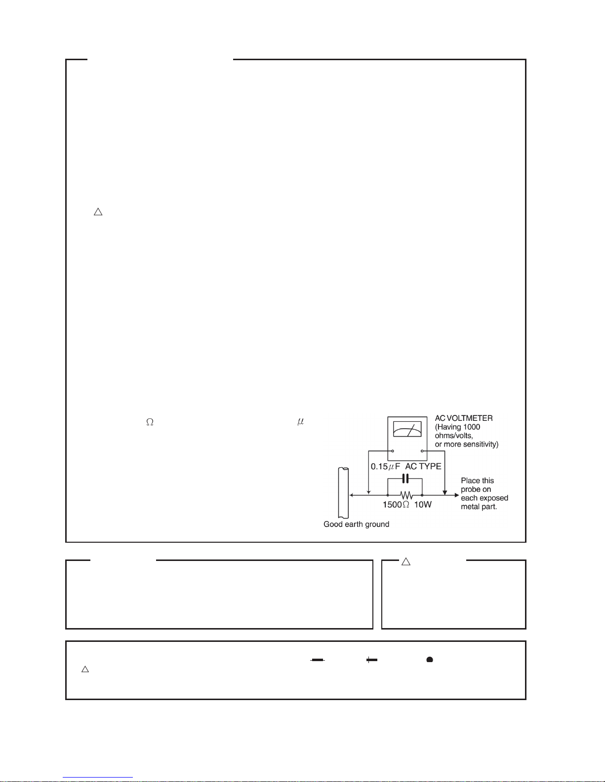
lAlternatecheck method
Plug theAC line cord directly into theAC outlet. Use anAC voltmeter having, 1,000 ohms per volt
ormore sensitivityin thefollowingmanner.Connect
a 1,500
10W resistor paralleled by a 0.15
F
AC-type capacitor between an exposed metal
partanda known good earth ground. Measure the
AC voltage across the resistor with the AC
voltmeter.
Movetheresistorconnectionto eachexposedmetal
part, particularly any exposed metal part having a
return path to the chassis, and meausre the AC
voltageacrosstheresistor.Now,reverse the plug in
theACoutletandrepeateachmeasurement.Voltage
measuredAnymustnotexceed0.75V AC (r.m.s.).
This corresponds to 0.5 mA AC (r.m.s.).
In regard with component parts appearing on the silk-screen printed side (parts side) of the PWB diagrams, the
parts that are printed over with black such as the resistor ( ), diode ( ) and ICP ( ) or identified by the
“!”mark nearby are critical for safety.
When replacing them, be sure to use the parts of the same type and rating as specified by the manufacturer.
(Except the J and C version)
Safety Precautions
!CAUTION
Burrs formed during molding may
be left over on some parts of the
chassis. Therefore, pay attention
to such burrs in the case of
preforming repair of this system.
Warning
1.Thisequipmenthasbeendesignedandmanufacturedtomeetinternationalsafetystandards.
2.Itisthelegalresponsibilityoftherepairertoensure thatthesesafetystandardsaremaintained.
3.Repairsmustbemadeinaccordance withtherelevantsafetystandards.
4.Itisessentialthatsafetycriticalcomponentsarereplacedbyapprovedparts.
5.Ifmainsvoltageselectorisprovided,check settingforlocalvoltage.

1-3
Important for laser products
1.CLASS1LASERPRODUCT
2. DANGER : Invisible laser radiation when open and inter
lock failed or defeated. Avoid direct exposure to beam.
3. CAUTION : There are no serviceable parts inside the Laser
Unit. Do not disassemble the Laser Unit. Replace the
complete Laser Unit if it malfunctions.
4. CAUTION : The compact disc player uses invisible laser
radiation and is equipped with safety switches which
prevent emission of radiation when the drawer is open
and the safety interlocks have failed or are defeated. It is
dangerous to defeat the safety switches.
5. CAUTION : If safety switches malfunction, the laser is able
to function.
6. CAUTION : Use of controls, adjustments or performance of
procedures other than those specified herein may result
in hazardous radiation exposure.
!CAUTION Please use enough caution not to
see the beam directly or touch it in
case of an adjustment or operation
check.
VARNING : Osynlig laserstrålning är denna del är
öppnad och spårren är urkopplad. Betrakta
ej strålen.
VARO : Avattaessa ja suojalukitus ohitettaessa olet
alttiina näkymättömälle lasersäteilylle. Älä
katso säteeseen.
ADVARSEL : Usynlig laserstråling ved åbning, når
sikkerhedsafbrydere er ude af funktion.
Undgå udsættelse for stråling.
ADVARSEL : Usynlig laserstråling ved åpning, når
sikkerhetsbryteren er avslott. Unngå
utsettelse for stråling.
REPRODUCTION ANDPOSITIONOFLABELS WARNING LABEL

1-4
Preventing static electricity
1.Grounding to prevent damage by static electricity
Electrostatic discharge (ESD), which occurs when static electricity stored in the body, fabric, etc. is
discharged, can destroy the laser diode in the traverse unit (optical pickup). Take care to prevent this
when performing repairs.
2.About theearthprocessing forthe destructionpreventionby static electricity
In the equipment which uses optical pick-up (laser diode), optical pick-up is destroyed by the static
electricity of the work environment.
Be careful to use proper grounding in the area where repairs are being performed.
2-1 Ground the workbench
Ground the workbench by laying conductive material (such as a conductive sheet) or an iron plate
over it before placing the traverse unit (optical pickup) on it.
2-2 Ground yourself
Use an anti-static wrist strap to release any static electricity built up in your body.
3. Handling the optical pickup
1. In order to maintain quality during transport and before installation, both sides of the laser diode on the
replacement optical pickup are shorted. After replacement, return the shorted parts to their original condition.
(Refer to the text.)
2. Do not use a tester to check the condition of the laser diode in the optical pickup.The testers internal power
source can easily destroy the laser diode.
4. Handling the CD changer unit (optical pickup)
1. Do not subject the CD changer unit (optical pickup) to strong shocks, as it is a sensitive, complex unit.
2. Cut off the shorted part of the flexible cable using nippers, etc. after replacing the optical pickup. For specific
details, refer to the replacement procedure in the text.
Remove the anti-static pin when replacing the CDchanger
unit. Be careful not to take too long a time when attaching it
to the connector.
3. Handle the flexible cable carefully as it may break when
subjected to strong force.
4. It is not possible to adjust the semi-fixed resistor that ad-
justs the laser power. Do not turn it.
Attention when traverse unit is decomposed
* Please refer to “Disassembly method ”in the text for pick
up and how to detach the CD changer mechanism.
1.Removethe CDchangerunit.
2.Disconnectthe harnessfrom connectoronthe CDmotor board.
3.Solder is put upbeforethecardwire is removed from connector
Cn601on the main board as shown in Fig.1 and Fig. 2.
(When the wire is removed without putting up solder, the CD
pick-up assembly might destroy.)
4. Pleaseremovesolderafter connectingthecardwire withCN601
when you install picking up in the substrate.

1-5
Disassembly method
Commencedisassemblyofthissetby removingthe main units and then proceed to the components andassemblies
inside the units.
Replacement of the fuses and the power IC
nTop cover
nCD changer unit
nFront panel assembly
nChassis unit
nCD changer unit
nRemoving the main PCB
nRemoving the CD changer mechanism assembly
nRemoving the CD pickup
nReplacing the loading motor and belt of the CD changer tray
nReplacing the CD tray rotor belt of CD changer, and removing the motor
nFront panel assembly
nRemoving the cassette deck mechanism
nRemoving the earphone jack PCB
nRemoving the control/FL PCB
nRemoving the switch PCB and ACTIVE BASS EX. switch PCB
nRemoving the cassette deck main motor, and replacing the main belts
nRemoving the leaf switches of the cassette deck mechanism
nRemoving the cassette deck heads
nChassis unit
nRemoving the 3-pin regulator
nRemoving the power amp and supply PCB and the Power Trans PCB
nRemoving the sub power PCB

1-6
<Disassembly of the main blocks of this set>
Replacement of the fuses and the power IC
nReplacing the fuses (See Fig.1, Fig.3)
nPrior to performing the following procedure, remove
theleftsideBOARDandremovetunerPCB (Fig.3,BB)
1. Replace the fuses inside.
[Caution] Besure tousefuses with thespecifiedratings.
nReplacing the power IC (See Fig.2 )
nPrior to performing the following procedure, remove
the topcover.
1.Remove thetwoscrews“A”fromtheheatsinkbetween
thepower IC.
2.Removethesolderfixingthe power IC.
nReplacing the heat sink cover
1. Remove the six screws from the back panel.
2. Pull the heat sink cover outward.

1-7
nRemoving the top cover and two sides
BOARD (See Fig.4 and 5)
1. Remove the six screws “B ” that retain the top cover
fromthe rearof the body.
2.Removethe eight screws “C ” and“D” thatretainthe
top from the two sides of the body.
3.Removethe top cover from the body by lifting ittoward
therear.

1-8
nRemoving the CD changer unit
(See Fig.6 and 9)
n Prior to performingthe following procedures,remove
thetop cover andboth sidesBOARD.
[Caution] Although the CD mechanism unit can be
removed without removing the CD tray
panel, it is still recommended to remove it
inordertopreventdamage.
a. Fromthefrontpanelsideofthisset,pushinthesections
marked with arrows and pull out the CD tray toward
thefront.
b. Remove the CD tray panel by pushing both of its
extremities upward in thedirection of thearrows.
c. Push the CD tray deep into the set.
1. Disconnect the card wires from the CD PCB CN704,
CN607,CN1101anddisconnectCN1(shieldwire)from
back panel.
2. From the rear of the set, remove the two screws “E ”
and two serews “G ”on the front panel left and right
side.
3. Handle the CDchanger unit rear, take out unit.
Fig.6

1-9
nRemoving the front panel assembly
(See Fig.10 and 11)
n Prior to performingthe following procedures,remove
thetopcover andboth sidesboard.
n Also remove the CDchanger unit.
1. Disconnect the parallel wire and card wire from the
connectors CN702, CN701, CN703, CN850 on the
poweramp andsupplyPCB.
2. Remove the two screws “H ”retaining the front panel
assembly onto the bottom of the body.
3. Remove the screw “I ”retaining the cassette deck
mechanism and then remove then GNDlug “b ”that
comes from the power amp and supply PCB.
4.Disengage the claws “c ”on both sides at the bottom
of the front panel assembly and then remove the
assembly.

1-10
<Disassembly of units and assembly inside
thisset>
nRemoving the CD PCB (See Fig.12 and 13)
n Prior to performingthe following procedures,remove
thetopcover andboth sidesboard.
n Also remove the CDchanger unit.
1. The two screws “E ”that retain the VCD assembly
shouldbe removed.
2.Disconnect the wires from CN602, CN603, CN604
and CN605 on the CD PCB, which is located on the
back side of the CDchanger unit.
3.Thetwo screws “J”thatretaintheCD PCB should be
removed.
4.RemovetheCDPCBbypullingit towardthe sidewhere
the CN601 is located.
5. Using solder, short the CDpickup to connect to short
round.
[Caution] After re-connecting the wires, be sure to
removetheshortingsolderfromtheGNDcon-
nection.
6.Disconnect the card wire from the connector CN601
on the main PCB and then remove the main PCB.

1-11
nRemoving the CD changer mechanism
assembly (See Fig.14 and 16)
n Prior to performingthe following procedures,remove
thetopcover andboth sidesboard.
n Also remove the CDchanger unit.
1. Remove the screws “d ”from the front chuch base of
theCDchanger mechanism unit.
2.TurntheCDchangermechanismcoverbaseandremove
thescrews“e ”connectingthe unit to the CDchanger
mechanism assembly.
3. Removing the four screws “k ”retaining the CD
mechanism holder assembly.
[Caution] WhenreplacingtheCDchangermechanism
assembly, be sure not to mistake the
positionsofthe silvercolorandcoppercolor
spring.

1-12
nRemoving the CD PCB (See Fig.17)
n Priortoperformingthefollowingprocedures,remove
thetopcover andbothsidesboard.
n Also remove the CDchanger unit.
n Also remove the CDchanger mechanism.
1. Widen the section “f ”.
2. While keeping the section “f ”wide open, push the
section“g ”in the direction of the arrow to remove the
shaft,andthenremovethe CDpickup.
nReplacingtheloadingmotor and rotor belt
of the CD changer (See Fig.18)
n Prior to performing the following procedure, remove
thetopcover.
n Also open the CD changer tray.
1.Removethe two screws “L” retainingtheCDchanger
trayloadingmotor.
2. Remove the two screws “M ” retaining the gear plate
and take it out, after remove the rotor belt from the
pulley.
nReplacingthe CD turn tableandremoving
the motor (See Fig. 19 and 20)
n Prior to performingthe following procedures,remove
thetopcover.
n Also remove the CDchanger unit.
1. Remove the one screws “N ”retaining the CD (Turn
table).
2. Remove the two screws “O ”retaining the stopper
brackets on both sides of the CDchanger unit.
3. Remove the stopper brackets from both sides of the
CDchanger unit.
4. Pull out the CDtray from the CDchanger unit, all the
wayand liftthe tray (u/~ ward)toremove.
5. Remove the gear and after push out the tray motor
locker and pull out the tray motor from the CDtray.

1-13
nRemoving the cassette deck mechanism
(See Fig.21)
n Prior to performing the following procedure, remove
thetopcover andboth sidesboard.
n Also remove the CDchanger unit.
n Also remove the front panel assembly.
1. Remove the five screws “Z ”retaining the cassette
deckmechanism.
nRemoving the earphonejackPCBAnd Mic
Jack PCB (See Fig.22)
n Prior to performing the following procedure, remove
thetopcover andbothsidesboard.
n Also remove the CDchanger unit.
n Also remove the front panel assembly.
1. Remove the screw with the washer, “P ”that retains
theearphonejackPCB.
nRemoving the control/FL PCB
(See Fig.23)
n Prior to performing the following procedure, remove
the top cover and both sides board.Also remove the
CDchangerunit.
n Also remove the CDchanger unit.
n Also remove the front panel assembly.
1.Remove the four screws“Q”thatretain the control/FL
PCB from the back of the front panel unit.

1-14
nRemoving the switch PCB and sound
mode and CD function switch PCB
(See Fig.23 to 26)
n Prior to performingthe following procedures,remove
thetopcover andboth sidesboard.
n Also remove the CDchanger unit.
n Also remove the front panel assembly.
1. Pull out the volume control knob and MIC Volume
Knobfromthe front of the frontpanelassembly.
2. Removethe four screws “Q”retaining the front panel
assembly.
3. Remove the control / FL PCB.
4. Remove the eleven screws “R ”retaining the switch
(key 1) PCB.
5. Remove the three screws “S ”retaining the sound
mode (key 2) switch PCB.
6. Remove two screws “T ”retaining the CD function
(key 3) switch PCB.

1-15
nRemoving the cassette deck main motor,
and replacing the main belts
(See Fig. 21, 27 and 28)
n Prior to performingthe following procedures,remove
thetopcover andboth sidesboard.
n Also remove the CDchanger unit.
n Also remove the front panel assembly.
1. Remove the five screws “z ”retaining the cassette
deckmechanism.
2. Remove the cassette deck mechanism.
3. Remove the two screws “t ”retaining the main motor
from the front side of the cassette deck.
[Caution] After attaching the main motor, check the
orientationofthemotor andthe polarity of
thewires.
4. From the backside of the cassette deck, remove the
main motor and two main belts.
[Caution] The lengths of the cassette A (playback
only) and cassette B (record/play) main
beltsaredifferent.Whenattachingthemain
belts, use the longer belt for cassetteA.
nRemoving the leaf switches of the cas-
sette deck mechanism
(See Fig. 21 and 29)
n Prior to performingthe following procedures,remove
thetopcover andboth sidesboard.
n Also remove the CDchanger unit.
n Also remove the front panel assembly.
1. Remove the five screws “O ”that retain the cassette
deckmechanism.
2. Remove the cassette deck mechanism.
3. Turn the cassette deck mechanism upside down.
4.Removethesolder from around the leaf switches.
5. Pull out the leaf switches from the front side of the
cassette deck mechanism.

1-16
nRemoving the cassette deck heads
(See Fig.21 to 30)
n Prior to performingthe following procedures,remove
thetopcover andbothsidesboard.
n Also remove the CDchanger unit.
n Also remove the front panel assembly.
1. Remove the five screws “O ”that retain the cassette
deckmechanism.
2.Removethe cassette deckmechanism and placeit so
that the front side faces up.
3. Remove the solder from the bottom side of the head
terminalanddisconnect the wire.
4. Remove the screw “U ”that retains the head.
5. Remove the screw “V ”that retains the head.
6. Hold the head and slide it in the direction of the arrow
toremoveit. Fig.31
nRemoving the 3-pin regulator
(See Q904, Q907, 31)
n Prior to performing the following procedures, remove
thetopcover andbothsidesboard.
1. Remove the two screws “A ”that connect the heat
sinkcover to the rear panel.
2. Pull the heat sink outward.
3.Removethe screw“W ”that retains the heat sink the
3-pinterminal regulator Q904,Q907.
4.Removethe solder fixingthe3-pinregulator.

1-17
nRemoving the power amp andsupply PCB
and the power trans PCB
(See Fig. 2, 32 to 34)
n Prior to performingthe following procedures,remove
thetopcover andboth sidesboard.
n Also remove heat sink cover.(Fig.3)
1.Removethetwoscrews “A ”connecting the heat sink
coverto the rear panel.(Fig.2)
2. Pull out the heat sink cover toward you.
3. Remove four(CA-MXK350V) screws “AA”form the
MX-K350Vback panelbetween the heatsink.
4.Remove the three screws “X ”that retain the speaker
terminalsandaux terminal.
5.Removethe screw “YY”and“Y”thatretainsthe rear
panel,andACswitchscrewthenremovetherear panel.
6. Disconnect the parallel wires from the connectors
FW951 on the power trans PCB.
7.Removethescrew “Z ”that retain the poweramp and
supplyPCB andthen remove the assembly.
8.Removethe clampofACpowercordfromthechassis.
9. Remove the four screws “AB ”that retain the power
transPCB andthen remove the assembly.

1-18
Adjustment method
Measurement instruments required
for adjustment
1. Low frequency oscillator
This oscillator should have a capacity to output 0dB
to 600ohm at an oscillation frequency of 50Hz-
20kHz.
2. Attenuator impedance : 600ohm
3. Electronic voltmeter
4. Frequency counter
5. Wow flutter meter
6. Test tape
VT712 : For Tape speed and wow flutter ( 3kHz)
VT703 : For Head angle(10kHz),Play back frequency
characteristics(1kHz), and dubbing fre-
quency characteristics (63,1,10kHz)
7. Blank tape
TAPE I : AC-225
8. Torque gauge : For play and back tension forward ;
TW2111A, Reverse ; TW2121A Fast Forward and
Rewind ; TW2231A
9. Test disc: CTS-1000(12cm),GRG-1211(8cm),
CD-T05A
10. Jitter meter
11. Television
Measurement conditions
(Select correctAC Line Volt.)
Power supply voltage
AC110/127/220/230-240V (50/60Hz) US/UX
Measurement
output terminal : Speaker out
: TP101(Measuring for TUNER
DECK/CD/VCD)
: Dummy load 6ohm
Adio input signal
AM modulation frequency : 400Hz
Modulation factor : 30%
FM modulation frequency : 400Hz
Frequency displacement : 22.5kHz
Frequency Range
AM US: 531kHz~1629kHz (9kHz)
530kHz~1710kHz (10kHz)
UX: 531kHz~1602kHz (9kHz)
530kHz~1600kHz (10kHz)
FM 87.5MHz~108MHz
Standard measurement positions of
volume and switch
Power: Standby (Light STANDBY Indicator)
S, A, BASS : OFF
Sound mode : OFF
Main VOL. : 0 Minimum
Travers mecha set position : Disc 1
Mic MIX VOL : MAX
ECHO : OFF
Precautions for measurement
1. Apply 30pF and 33kohm to the IF sweeper output side
and 0.082 F and 100kohm in series to the sweeper
input side.
2. The IF sweeper output level should be made as low as
possible within the adjustable range.
3. Since the IF sweeper is a fixed device, there is no
need to adjust this sweeper.
4. Since a ceramic oscillator is used, there is no need to
perform any MPX adjustment.
5. Since a fixed coil is used, there is no need to adjust
the FM tracking.
6. The input and output earth systems are separated. In
case of simultaneously measuring the voltage in both
of the input and output systems with an electronic
voltmeter for two channels, therefore, the earth should
be connected particularly.
7. In the case of BTL connection amplifier, the minus
terminal of speaker is not for earthing. Therefore, be
sure not to connect any other earth terminal to this
terminal. This system is of an OTL system.

1-19
nArrangement of adjusting positions
nTape recorder section
nTuner section
Note: The adjustment of CD section is not required.
Items Measurement
conditions Measurement method Standard
values Adjusting
positions
Cassette Head
Azimuth Alignments Test tape :
VT703 (10kHz)
Measurement
output terminal :
Left and Right
speaker output
(6-ohm loaded)
or Headphone
Output
(32-ohm loaded)
1. Playback the test tape VT703 (10KHz) or equivalent.
2. Adjust the head azimuth screw to obtain maximum
output and both output of L / R is in 3dB.
3. Put on the screw lock paint after alignments.
Maximum output Adjust the
head azimuth
screw only
when the head
has been
changed.
Recording Bias
Frequency Alignment Test tape :
TYPE IAC-225
Measurement
output terminal :
Erase head
terminal
(CN308 8-Pin)
1. Insert the recording tape in deck-B.
2. Starting the recording.
3. Adjust the oscillation frequency to 80KHz+/-3KHz
by core of Oscillation coil of L301.
80kHz+/-3kHz Use the High-
Impedance
Probe or
Frequency
counter input.
Items Measurement
conditions Measurement method Standard
values Adjusting
positions
AM Tracking
Alignments Input signal:
530kHz(529kHz)
600kHz(603kHz)
Adjustment
point: Antenna
coil (L2)
1. Set the Signal Generator signal to 530KHz(529KHz)
the feed to Loop Antenna.
2. Receiving the signal and the adjust the OSC coil (L2)
obtain the V.T is 1.40V +/-0.05V.
3. Change the receiving frequencyto 600KHz(603KHz).
4. Adjust the Antenna coil ( L2 ) obtain maximum
sensitivity .(Adjust the SSG output to out of AGC
range.)
V.T :
1.40V+/-0.05V
Maximum
sensitivity
Adjust the OSC
coil only when
the AM coil
block has been
changed.
AM IFT
Alignments Input signal:
530kHz(529kHz)
Adjustment
point: IFT (T1)
1. Set the receiving frequency to 530KHz(529KHz ).
2. Feed the 450KHzsignal to AM antenna input.
3. Adjust the IFT Block T1 obtain to maximum
output.(Adjust the SSG output to out of AGC
range.)
Maximum output Adjust the IFT
only when the
IFT block has
been changed.

1-20
Flow of functional operation until TOC read
Other manuals for MX-K350V
1
This manual suits for next models
2
Table of contents
Other JVC Stereo System manuals