JVC AV-29QH4BU User manual

SERVICE MANUAL
COPYRIGHT © 2005 Victor Company of Japan, Limited No.YA086
2005/2
COLOUR TELEVISION
YA08620052
AV-29QH4BU,
AV-29QH4SU
TABLE OF CONTENTS
1 PRECAUTION. . . . . . . . . . . . . . . . . . . . . . . . . . . . . . . . . . . . . . . . . . . . . . . . . . . . . . . . . . . . . . . . . . . . . . . . . 1-4
2 SPECIFIC SERVICE INSTRUCTIONS . . . . . . . . . . . . . . . . . . . . . . . . . . . . . . . . . . . . . . . . . . . . . . . . . . . . . . 1-5
3 DISASSEMBLY . . . . . . . . . . . . . . . . . . . . . . . . . . . . . . . . . . . . . . . . . . . . . . . . . . . . . . . . . . . . . . . . . . . . . . . 1-6
4 ADJUSTMENT . . . . . . . . . . . . . . . . . . . . . . . . . . . . . . . . . . . . . . . . . . . . . . . . . . . . . . . . . . . . . . . . . . . . . . . 1-10
5 TROUBLESHOOTING . . . . . . . . . . . . . . . . . . . . . . . . . . . . . . . . . . . . . . . . . . . . . . . . . . . . . . . . . . . . . . . . . 1-20
DVD
RM-C1512
VCR
?
132
465
798
ZOOM
PICTURE
MENUAV
P
P
0
TV

1-2 (No.YA086)
SPECIFICATION
Design & specifications are subject to change without notice.
Item Content
Dimensions ( W ×H ×D ) 78.5cm ×61.5cm ×50cm
Mass 41.7kg
TV RF System B/G, D/K, L/L'
Colour System TV Mode PAL / SECAM
Video Mode PAL / SECAM / NTSC 3.58 / NTSC 4.43
Sound System A2 (B/G, D/K), NICAM (B/G, D/K, L/L')
Teletext System Fastext / TOP / WST
Tuning System Frequency synthesizer tuning system
Receiving Frequency VHF(VL)
VHF(VH)
UHF
CATV
46.25MHz - 168.25MHz
175.25MHz - 463.25MHz
471.25MHz - 863.25MHz
S01 - S41 & S75 - S79
Intermediate Frequency VIF
SIF
38.9MHz (B/G, D/K, L) / 33.9MHz (L')
33.4MHz (5.5MHz:B/G) / 32.9MHz (6.0MHz:D/K) /
32.4MHz (6.5MHz:L) / 40.4MHz (6.5MHz:L')
Colour Sub Carrier Frequency PAL
SECAM
NTSC
4.43MHz
4.40625MHz / 4.43MHz
3.58MHz / 4.43MHz
Power Input AC220V - AC240V, 50Hz
Power Consumption 130W (Max) / 3W (Standby)
Aerial Input Terminal 75Ωunbalanced, coaxial
Picture Tube Size Visible size : 68cm (29”), Measured diagonally (H: 54.1cm ×V: 40.6cm)
High Voltage 31.2kV (at zero bean current)
Speaker 5.7cm ×12.6cm, Oval type ×2 / 8.0cm Round type (tweeter) ×2
Audio Output 10W + 10W (THD10%)
EXT-1 Input / Output 21-pin Euro connector (SCRAT socket) ×1
EXT-2 Input / Output 21-pin Euro connector (SCRAT socket) ×1
EXT-3 Input Video
Audio (L/R)
1V(p-p) 75Ω, RCA pin jack ×1
500mV(rms) (-4dBs), High Impedance, RCA pin jack ×2
Headphone jack Stereo mini jack 3.5mm
Remote Control Unit VE-30021286 (RM-C1512B) (AA/R06 dry battery ×2) [AV-29QH4BU]
VE-30021287 (RM-C1512S) (AA/R06 dry battery ×2) [AV-29QH4SU]

(No.YA086)1-5
SECTION 2
SPECIFIC SERVICE INSTRUCTIONS
2.1 FEATURES
• It is a remote controlled color television.
• It can tune cable channels.
• Controlling the TV is very easy by its menu driven system.
• It has two Euroconnector sockets for external device (such as
video recorder, video games, audio set, etc.)
• Front AV Input (EXT-3) available.
• Stereo sound systems (A2 + Nicam) are available.
• Full function Teletext (Fastext, Toptext & WST).
• It is possible to connect headphone.
• Direct channel access.
• APS (Automatic Programming System).
• All programs can be named.
• Forward or backward automatic tuning.
• Sleep timer.
• Child Lock.
• Blue Background
• Comb Filter
• NTSC Playback.
•T-VLink
• Automatic sound muting when no transmission.
• 5 minutes after the broadcasting (close down), the TV switches
itself automatically to stand-by mode.
• WSS (Wide Screen Signaling)
2.2 MAIN DIFFERENCE LIST
Items AV-29QH4BU AV-29QH4SU
CABINET COLOUR BLACK SILVER
REMOTE CONTROL UNIT VE-30021286 (RM-C1512B) VE-30021287 (RM-C1512S)

1-6 (No.YA086)
SECTION 3
DISASSEMBLY
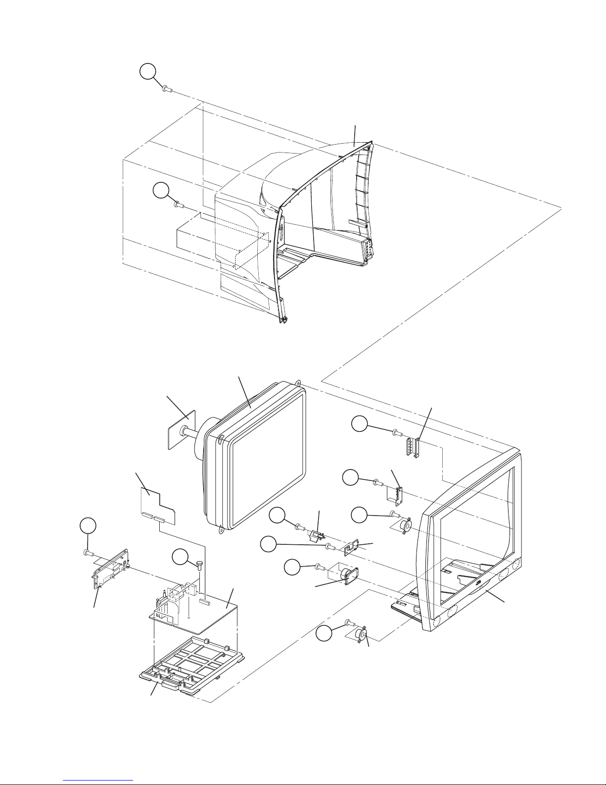
3.1 DISASSEMBLY PROCEDURE
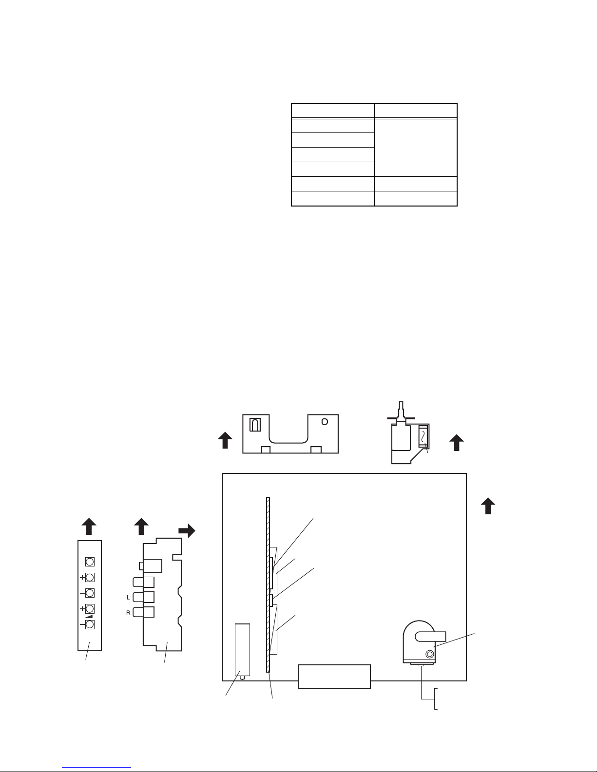
3.1.1 REMOVING THE REAR COVER
(1) Unplug the power cord.
(2) Remove the 8 screws [A].
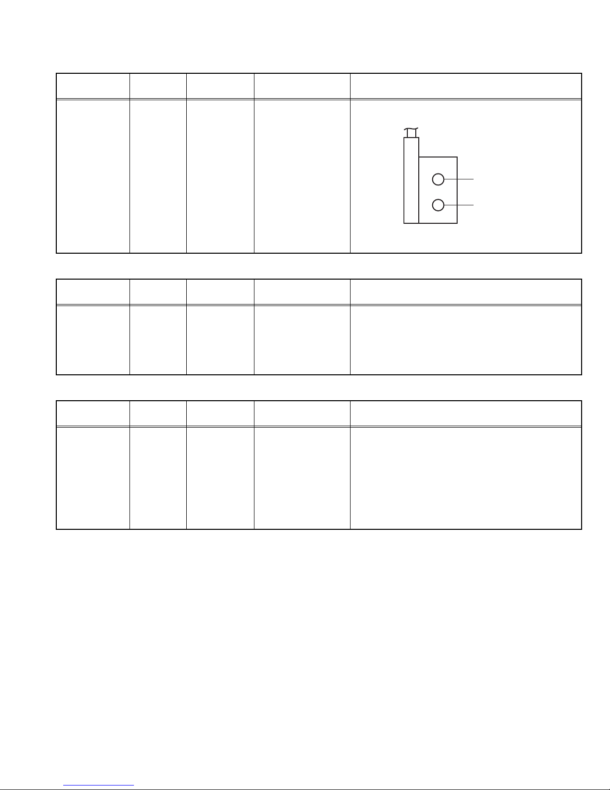
(3) Remove the 4 screw [B].
(4) Withdraw the REAR COVER toward you.
3.1.2 REMOVING THE BACK DOOR
• Remove the REAR COVER.
(1) Remove the 2 screws [C].
(2) Withdraw the BACK DOOR toward you.
3.1.3 REMOVING FEATURE BOX PWB
• Removing the REAR COVER.
(1) Disconnect the connector PL409 and PL410 on the MAIN
PWB.
(2) Raise up the both sides and disconnect the FEATURE
BOX PWB.
3.1.4 REMOVING THE MAIN PWB
• Removing the REAR COVER.
(1) Remove the 4 screws [D].
(2) Slightly raise the both sides of the MAIN PWB by hand and
withdraw MAIN PWB backward.
(If necessary, take off the wire clamp, connectors etc.)
(Be careful enough when developing a MAIN PWB.)
3.1.5 REMOVING THE SIDE CONTROL PWB
• Removing the REAR COVER.
• Removing the CHASSIS.
(1) Remove the 2 screws [E], and remove the SIDE
CONTROL PWB.
3.1.6 REMOVING THE AV & HEADPHONE PWB
• Removing the REAR COVER.
• Removing the CHASSIS.
(1) Remove the 3 screws [F], and remove the AV &
HEADPHONE PWB.
3.1.7 REMOVING THE POWER SWITCH PWB
• Removing the REAR COVER.
• Removing the CHASSIS.
(1) Remove the 2 screws [G], and remove the POWER
SWITCH.
3.1.8 REMOVING THE LED PWB
• Removing the REAR COVER.
• Removing the CHASSIS.
• Removing the POWER SWITCH PWB
(1) Remove the 2 screws [H], and remove the LED PWB.
3.1.9 REMOVING THE WOOFER & TWEETER
• Removing the REAR COVER.
(1) Remove the 4 screws [I], and remove the WOOFER.
(2) Remove the 2 screws [J], and remove the TWEETER.
(3) Remove an opposite side similarly.
3.1.10 CHECKING THE PW BOARD
To check the back side of the PW Board.
1) Pull out the PW Board. (Refer to REMOVING THE MAIN
PWB).
2) Erect the PW Board vertically so that you can easily check
the back side of the PWB.
[CAUTION]
• When erecting the PW Board, be careful so that there will be
no contacting with other PW Board.
• Before turning on power, make sure that the wire connector
is properly connected.
• When conducting a check with power supplied, be sure to
confirm that the CRT EARTH WIRE (BRAIDED ASS'Y) is
connected to the CRT SOCKET PWB.
3.1.11 WIRE CLAMPING AND CABLE TYING
1. Be sure to clamp the wire.
2. Never remove the cable tie used for tying the wires together.
Should it be inadvertently removed, be sure to tie the wires
with a new cable tie.

(No.YA086)1-7
Fig.1
FEATURE BOX PWB
LED PWB
POWER
SWICTH PWB
AV & HEADPHONE
PWB
SIDE
CONTROL PWB
(x4)
(x8)
MAIN PWB
CRT SOCKET
PWB
FRONT CABINET
SPEAKE
(WOOFER)
SPEAKE
(TWEETER)
PICTURE TUBE
CHASSIS FRAME
J
(x2)
(x2)
I
(x4)
G
(x2)
H
(x2)
D
(x4)
C
(x2)
F
(x3)
E
B
A
(x2)
REAR COVER
BACK DOOR
J

1-8 (No.YA086)
3.2 SETTING OF THE LAST MEMORY FOR SHIPMENT
3.2.1 USER SETTING VALUES
3.2.2 SETTING APS BIT IN SERVICE MENU
(1) Press [INFORMATION] and [MUTING] keys to enter the service menu.
(2) Press [GREEN] key to select the VIDEO.
(3) Press FUNCTION []/[] keys to select the APS items.
(4) Press FUNCTION []/[] keys to change the value to "ON".
(5) Press [INFORMATION] key to store the change value.
(6) Press [MENU] key to exit the service mode.
Setting item Setting value Setting item Setting value
PICTURE MENU INSTALL
BRIGHTNESS
These adjust are automatically
restored when APS bit in
Service menu is set.
The procedure for setting APS
bit is described bellow.
LANGUAGE ENGLISH
CONTRAST COUNTRY Other
COLOUR EXT-2 OUTPUT TV
SHARPNESS
COLOUR TEMP
ZOOM
HUE (only NTSC)
SOUND MENU FEATURE MENU
BALANCE Center SLEEP TIMER OFF
BASS Center CHILD LOCK OFF
TREBLE Center
HYPER SOUND OFF

1-10 (No.YA086)
SECTION 4
ADJUSTMENT
4.1 ADJUSTMENT PREPARATION
(1) You can make the necessary adjustments for this unit with
either the Remote Control Unit or with the adjustment tools
and parts as given below.
(2) Adjustment with the Remote Control Unit is made on the
basis of the initial setting values, however, the new setting
values which set the screen to its optimum condition may
differ from the initial settings.
(3) Make sure that AC power is turned on correctly.
(4) Turn on the power for set and test equipment before use,
and start the adjustment procedures after waiting at least
30 minutes.
(5) Unless otherwise specified, prepare the most suitable
reception or input signal for adjustment.
(6) Never touch any adjustment parts which are not specified
in the list for this adjustment - variable resistors,
transformers, condensers, etc.
(7) Presetting before adjustment.
Unless otherwise specified in the adjustment instructions,
preset the following functions with the remote control unit:
4.2 MEASURING EQUIPMENT
(1) DC voltmeter (or digital voltmeter)
(2) Signal generator (Pattern generator)
: [PAL / SECAM / NTSC]
(3) Remote control unit
4.3 ADJUSTMENT ITEM
• FOCUS ADJUSTMENT
• SCREEN ADJUSTMENT
• AGC ADJUSTMENT
• DEFLECTION CIRCUIT ADJUSTMENT
• VIDEO CIRCUIT ADJUSTMENT
4.4 ADJUSTMENT LOCATIONS
Setting item Setting value
BRIGHTNESS
Center
CONTRAST
COLOUR
SHARPNESS
COLOUR TEMP NORMAL
ZOOM AUTO
FRONT
FEATURE BOX
PWB
IC750 (MEMORY)
IC752 (MI-COM)
PL409
PL4083
FBT
UPPER : FOCUS
LOWER : SCREEN
VIDEO
HEADPHONE
IC
LED
FUSE
SIDE CONTROL
PWB
LED PWB POWER SWITCH
PWB
AV & HEADPHONE
PWB
FRONT
TOP
TOP
TOP FRONT
MENU
P/Ch
MAIN PWB
AV-1(SCART)
AV-2(SCART)
TUNER
TU200

(No.YA086)1-11
4.5 BASIC OPERATION OF SERVICE MODE
4.5.1 HOW TO ENTER THE SERVICE MODE
(1) Press the INFORMATION key and MUTING key
simultaneously, and the SERVICE MENU 1 screen (Fig.1)
will be displayed.
Fig.1
(2) While the SERVICE MENU 1 screen is displayed, press
the BLUE key for access to the SERVICE MENU 2 (Fig.2).
Fig.2
4.5.2 SELECTION OF ADJUSTMENT ITEMS
(1) Enter the SERVICE MODE
(2) Press the COLOUR (RED,GREEN,YELLOW or BLUE)
key and select the SERVICE MENU 1 section. (refer to
next page.)
(3) Press the FUNCTION []/[] key to select the adjustment
item.
(4) Press the FUNCTION []/[] key to set the setting value.
(5) Press the [INFORMATION] key to store the setting value.
4.5.3 HOW TO EXIT SERVICE MODE
(1) Press the [MENU] key.
PRODUCTION i >STORE MENU>EXIT
H/V (FULL MODE)
V-SHIFT
V-SIZE
H-SHIFT
H-SIZE
S-COR
LINRT
ANGLE
BOW
TRAPEZ
PARAB
U.COR
L.COR
TILT
TRPZD
NTSCHS
TXTV
HS04_3
JVC52 ****
**.**.****
VIDEO
WdR
WdG
WdB
CuR
CuG
CuB
G2Cu
YDP
AGC
APSW
APS
T_T
T_P
YDS
YDN
EXT3
DVD
C.M
4:3
SERVICE
***
***
***
***
***
***
***
***
***
***
***
***
***
***
***
***
***
***
***
***
****
****
***
***
***
***
***
***
***
***
***
***
***
***
***
***
SERVICE MENU 1
PRODUCTION i >STORE MENU>EXIT
ADJUSTMENTS
PIP CNTRST
PIP YDelay
PIP Frame
EHTH SA1
EHTV SA1
EHTH SA2
EHTV SA2
EHTV THRS
SVDEL
OSD CONT
OSD BRI
TEXT BRI
TXTCONT
INIT NVM
Prescaler
FM
NICAM
I2S
SCART
OPTIONS
0. HPHONE
1. CRT
2. S-VHS
3. f(IF)
4. Turk
5. RF
6. FRONT
7. MLAN
8. VD
9. CTI
: . AVL
***
***
***
***
***
***
***
***
***
***
***
SYSTEM
0. PAL B/G
1. PAL D/K
2. PAL I
3. SECAM B/G
4. SECAM D/K
5. SECAM L/L
6. AUST.
***
***
***
***
***
***
***
***
***
***
***
***
***
***
***
***
***
***
***
***
***
***
***
***
SERVICE MENU 2
MUTE key
REMOTE CONTROL UNIT key NAME
colour key
RED
GREEN
YELLOW
BLUE
INFORMATION key
UP / DOWN
[ ]/[ ] key
TELETEXT key
LEFT / RIGHT
[ ]/[ ] key
MENU key

1-12 (No.YA086)
4.5.4 COLOUR KEY FUNCTION AND SCREEN DISPLAY
PRODUCTION i >STORE MENU>EXIT
H/V (FULL MODE)
V-SHIFT
V-SIZE
H-SHIFT
H-SIZE
S-COR
LINRT
ANGLE
BOW
TRAPEZ
PARAB
U.COR
L.COR
TILT
TRPZD
NTSCHS
TXTV
HS04_3
JVC*******
*******
VIDEO
WdR
WdG
WdB
CuR
CuG
CuB
G2Cu
YDP
AGC
APSW
APS
T_T
T_P
YDS
YDN
EXT3
DVD
C.M
4:3
SERVICE
***
***
***
***
***
***
***
***
***
***
***
***
***
***
***
***
***
***
***
***
****
****
***
***
***
***
***
***
***
***
***
***
***
***
***
***
PRODUCTION i >STORE MENU>EXIT
ADJUSTMENTS
PIP CNTRST
PIP YDelay
PIP Frame
EHTH SA1
EHTV SA1
EHTH SA2
EHTV SA2
EHTV THRS
SVDEL
TU TYPE
OSD CONT
OSD BRI
TEXT BRI
TXTCONT
INIT NVM
Prescaler
FM
NICAM
I2S
SCART
OPTIONS
0. HPHONE
1. CRT
2. S-VHS
3. f(IF)
4. Turk
5. RF
6. FRONT
7. MLAH
8. VD
9. CTI
: . AVL
***
***
***
***
***
***
***
***
***
***
***
SYSTEM
0. PAL B/G
1. PAL D/K
2. PAL I
3. SECAM B/G
4. SECAM D/K
5. SECAM L/L
6. AUST.
***
***
***
***
***
***
***
***
***
*
***
***
***
***
***
***
***
***
***
***
***
***
***
***
***
***
***
P.M. FACTORY SET MENU> SERVICE
FATORY SETTINGS
Brightness
Contrast
Colour
Brightness
Contrast
Colour
Brightness
Contrast
Colour
Brightness
Contrast
Colour
WdR
WdG
WdB
WdR
WdG
WdB
USER
USER
USER
BRIGHT
BRIGHT
BRIGHT
STANDARD
STANDARD
STANDARD
SOFT
SOFT
SOFT
WARM
WARM
WARM
COOL
COOL
COOL
***
***
***
***
***
***
***
***
***
***
***
***
***
***
***
***
***
***
FACTORY SETTINGS
SERVICE MENU 1
Colour key function in the SERVICE MENU
SERVICE MENU 2
RED key
select H/V
GREEN key
select VIDEO
GREEN key twice
access FACTRY SETTINGS
RED key
select ADJUSTMENT
GREEN key
select Prescaler
BLUE key
select SERVICE
BLUE key
select OPTIONS
YELLOW key
select SYSTEM
Do Not Adjust
Colour key Press time
RED
GREEN
YELLOW
BLUE
onece
twice
onece
twice
onece
twice
onece
twice
Select menu
H/V
VIDEO
---
SERVICE (SERVICE MENU 2)
---
---
---
---
colour key location
BLUE
YELLOW
GREEN
RED

(No.YA086)1-13
4.6 ADJUSTMENTS PROCEDURE
4.6.1 FOCUS ADJUSTMENT
4.6.2 SCREEN ADJUSTMENT
4.6.3 AGC ADJUSTMENT
Item Measuring
instrument Test point Adjustment part Description
FOCUS
adjustment
Signal
generator
Remote
control unit
FOCUS VR
[On the FBT]
(1) Receive a crosshatch signal.
(2) Adjust FOCUS VR on the FBT as thin as possible.
FBT
FOCUS VR
SCREEN VR
Item Measuring
instrument Test point Adjustment part Description
SCREEN
adjustment
Remote
control unit
SCREEN VR
[On the FBT]
(1) Press [MUTING] and [INFORMATION] key at the
sametime. And then press [BLUE] and [TELETEXT]
key respectively.
Enter screen adjustment from the service mode.
(2) Adjust the SCREEN VR until the "G2 ADJUST OK"
sign appears.
Item Measuring
instrument Test point Adjustment part Description
AGC
adjustment
Signal
generator
Remote
control unit
DC volt meter
AGC (1) Receive a PAL BG signal at 60dBµV RF signal level.
(2) Enter the SERVICE MODE.
(3) Press the [GREEN] key to enter the VIDEO
adjustment group.
(4) Select AGC.
(5) Adjust AGC by pressing until voltage at pin 1 of
TUNER is equal to 3.0V.
(6) Press the [INFORMATION] key to memorize the set
value.

1-14 (No.YA086)
4.6.4 DEFLECTION CIRCUIT ADJUSTMENT
Item Measuring
instrument Test point Adjustment part Description
VERTICAL
SHIFT
adjustment
Signal
generator
Remote
control unit
V-SHIFT (1) Receive a circle pattern signal.
(2) Enter the SERVICE MODE.
(3) Press the [RED] key to enter the H/V adjustment
group.
(4) Select V-SHIFT.
(5) Adjust V-SHIFT to make A=B.
(6) Check and readjust V-SHIFT item if the adjustment
becomes improper after some other geometric
adjustments are done.
(7) Press the [INFORMATION] key to memorize the set
value.
VERTICAL
SIZE
adjustment
Signal
generator
Remote
control unit
V-SIZE (1) Receive a crosshatch signal.
(2) Enter the SERVICE MODE.
(3) Press the [RED] key to enter the H/V adjustment
group.
(4) Select V-SIZE.
(5) Adjust V-SIZE until horizontal black lines on both the
upper and lower part of the crosshatch pattern
become very closeted the upper and lower
horizontal sides of picture size and nearly about to
disappear.
(6) Check and readjust V-SIZE item if the adjustment
becomes improper after some other geometric
adjustments are done.
(7) Press the [INFORMATION] key to memorize the set
value.
VERTICAL
S-CORRECTION
& LINEARITY
adjustment
Signal
generator
Remote
control unit
S-COR
LINRT
(1) Receive a crosshatch signal.
(2) Enter the SERVICE MODE.
(3) Press the [RED] key to enter the H/V adjustment
group.
(4) Select S-COR.
(5) Adjust S-COR until the size of squares on both the
upper and lower part of crosshatch pattern become
equal to the squares laying on the vertical center of
the cross-hatch pattern.
(6) Check and readjust S-COR item if the adjustment
becomes improper after some other geometric
adjustments are done.
(7) Press the [INFORMATION] key to memorize the set
value.
(8) Select LINRT.
(9) Adjust LINRT until all the size of squares of the
cross-hatch pattern become in equal size from the
top of the screen to its bottom of the whole screen.
(10) Check and readjust LINRT item if the adjustment
becomes improper after some other geometric
adjustments (especially after than S-COR
adjustment) are done.
(11) Press the [INFORMATION] key to memorize the set
value.
A
B
Screen
size
Very close
Very close
Picture
size
100%
UPPER
CENTER
LOWER

(No.YA086)1-15
HORIZONTAL
SHIFT
adjustment
Signal
generator
Remote
control unit
H-SHIFT (1) Receive a circle pattern signal.
(2) Enter the SERVICE MODE.
(3) Press the [RED] key to enter the H/V adjustment
group.
(4) Select H-SHIFT.
(5) Adjust H-SHIFT to make C=D.
(6) Check and readjust H-SHIFT item if the adjustment
becomes improper after some other geometric
adjustments are done.
(7) Press the [INFORMATION] key to memorize the set
value.
HORIZONTAL
SIZE
adjustment
Signal
generator
Remote
control unit
H-SIZE (1) Receive a cross-hatch signal.
(2) Enter the SERVICE MENU.
(3) Press the [RED] key to enter the H/V adjustment
group.
(4) Select H-SIZE.
(5) Adjust H-SIZE until vertical lines on both the left and
right part of the cross-hatch will be visible nor screen
will be so wide.
(6) Check and readjust H-SIZE item if the adjustment
becomes improper after some other geometric
adjustments are done.
(7) Press the [INFORMATION] key to memorize the set
value.
ANGLE
adjustment
Signal
generator
Remote
control unit
ANGLE (1) Receive a crosshatch signal.
(2) Enter the SERVICE MODE.
(3) Press the [RED] key to enter the H/V adjustment
group.
(4) Select ANGLE.
(5) Adjust ANGLE until the vertical lines of the
crossatch pattern become straight.
(6) Check and readjust ANGLE item if the adjustment
becomes improper after some other geometric
adjustments are done.
(7) Press the [INFORMATION] key to memorize the set
value.
Item Measuring
instrument Test point Adjustment part Description
CD
Screen size
Very
close
Very
close
Picture size 100%

1-16 (No.YA086)
BOW
adjustment
Signal
generator
Remote
control unit
BOW (1) Receive a crosshatch signal.
(2) Enter the SERVICE MODE.
(3) Press the [RED] key to enter the H/V adjustment
group.
(4) Select BOW.
(5) Adjust BOW until the vertical lines become straight.
(6) Check and readjust BOW item if the adjustment
becomes improper after some other geometric
adjustments are done.
(7) Press the [INFORMATION] key to memorize the set
value.
NOTE :
In case where there is a bow-shaped distortion of
images on the screen. (Figure)
TRAPEZIUM
adjustment
Signal
generator
Remote
control unit
TRAPEZ (1) Receive a crosshatch signal.
(2) Enter the SERVICE MODE.
(3) Press the [RED] key to enter the H/V adjustment
group.
(4) Select TRAPEZ.
(5) Adjust TRAPEZ until vertical lines, especially lines at
the sides of the picture frame become parallel to the
both sides of picture tubes as close as possible.
(6) Check and readjust TRAPEZ item if the adjustment
becomes improper after some other geometric
adjustments are done.
(7) Press the [INFORMATION] key to memorize the set
value.
SIDE PIN
adjustment
Signal
generator
Remote
control unit
PARAB (1) Receive a crosshatch signal.
(2) Enter the SERVICE MODE.
(3) Press the [RED] key to enter the H/V adjustment
group.
(4) Select PARAB.
(5) Adjust PARAB until vertical lines close to the both
sides of the picture frame become straight to vertical
sides of picture tube without any bending to left or to
right side of the screen.
(6) Check and readjust PARAB item if the adjustment
becomes improper after some other geometric
adjustments are done.
(7) Press the [INFORMATION] key to memorize the set
value.
Item Measuring
instrument Test point Adjustment part Description
Parallel
Straight

(No.YA086)1-17
CORNER
adjustment
Signal
generator
Remote
control unit
U.COR
L.COR
(1) Receive a crosshatch signal.
(2) Enter the SERVICE MODE.
(3) Press the [RED] key to enter the H/V adjustment
group.
(4) Select U.COR.
(5) Adjust U.COR until vertical lines at the upper corners
of the picture frame become vertical and parallel to
vertical corner sides of picture tube.
(6) Check and readjust U.COR item if the adjustment
becomes improper after some other geometric
adjustments are done.
(7) Select L.COR.
(8) Adjust L.COR until vertical lines at the lower corners
of the picture frame become vertical and parallel to
vertical corner sides of picture tube.
(9) Check and readjust L.COR item if the adjustment
becomes improper after some other geometric
adjustments are done.
(10) Press the [INFORMATION] key to memorize the set
value.
ROTATION
adjustment
Signal
generator
Remote
control unit
TILT (1) Receive a crosshatch signal.
(2) Enter the SERVICE MODE.
(3) Press the [RED] key to enter the H/V adjustment
group.
(4) Select TILT.
(5) Adjust TILT to rotate the complete master clockwise
and counter clockwise depending on the CRT.
(6) Check and readjust TRAPEZ item if the adjustment
becomes improper after some other geometric
adjustments are done.
(7) Press the [INFORMATION] key to memorize the set
value.
NTSC
HORIZONTAL
SIZE
adjustment
Signal
generator
Remote
control unit
NTSCHS (1) Receive a NTSC crosshatch signal.
(2) Enter the SERVICE MODE.
(3) Press the [RED] key to enter the H/V adjustment
group.
(4) Select NTSCHS.
(5) Adjust NTSCHS until vertical lines on both the left
and right part of the cross-hatch will be visible nor
screen will be so wide.
(6) Check and readjust TRAPEZ item if the adjustment
becomes improper after some other geometric
adjustments are done.
(7) Press the [INFORMATION] key to memorize the set
value.
Item Measuring
instrument Test point Adjustment part Description
Straight Straight
Screen size
Very
close
Very
close
Picture size 100%

1-18 (No.YA086)
TELETEXT
VERTICAL
SIZE
adjustment
Signal
generator
Remote
control unit
TXTV (1) Receive a crosshatch signal.
(2) Enter the SERVICE MODE.
(3) Press the [RED] key to enter the H/V adjustment
group.
(4) Select TXTV.
(5) Adjust TXTV to adjust the proper vertical size of
Teletext screen.
(6) Check and readjust TRAPEZ item if the adjustment
becomes improper after some other geometric
adjustments are done.
(7) Press the [INFORMATION] key to memorize the set
value.
4:3 TUBE
adjustment
Signal
generator
Remote
control unit
HS04_3 (1) Receive a crosshatch signal.
(2) Enter the SERVICE MODE.
(3) Press the [RED] key to enter the H/V adjustment
group.
(4) Select HS04_3.
(5) Adjust HS04_3 to adjust the proper horizontal size of
4:3 tube.
(6) Press the [INFORMATION] key to memorize the set
value.
Item Measuring
instrument Test point Adjustment part Description

(No.YA086)1-19
4.6.5 VIDEO CIRCUIT ADJUSTMENT
Item Measuring
instrument Test point Adjustment part Description
WHITE
BALANCE
adjustment
Signal
generator
Remote
control unit
WdR
WdG
WdB
(1) Receive a black & white signal.
(2) Enter the SERVICE MODE.
(3) Press the [GREEN] key to enter the VIDEO
adjustment group.
(4) Select WdR, WdG and WdB respectively.
(5)
Adjust
WdR
,
WdG
and
WdB
respectively, until the
white part turns to pure white without any other colour.
(6) Press the [INFORMATION] key to memorize the set
value.
COLOUR
CUTOFF
LEVEL
adjustment
Signal
generator
Remote
control unit
CuR
CuG
CuB
(1) Receive a crosshatch signal.
(2) Enter the SERVICE MODE.
(3) Press the [GREEN] key to enter the VIDEO
adjustment group.
(4) Select CuR, CuG and CuB respectively.
(5) Adjust CuR, CuG and CuB respectively, and set the
values of these items as 64 (contrast).
(6) Press the [INFORMATION] key to memorize the set
value.
PAL
Y DELAY
adjustment
Signal
generator
Remote
control unit
YDP (1) Receive a PAL colour bar signal.
(2) Enter the SERVICE MODE.
(3) Press the [GREEN] key to enter the VIDEO
adjustment group.
(4) Select YDP.
(5)
Adjust
YDP
until the colour transients on the colour bar
pattern becomes as sharper and possible as colours
between transients do not mix with each other.
(6) Press the [INFORMATION] key to memorize the set
value.
SECAM
Y DELAY
adjustment
Signal
generator
Remote
control unit
YDS (1) Receive a SECAM colour bar signal.
(2) Enter the SERVICE MODE.
(3) Press the [GREEN] key to enter the VIDEO
adjustment group.
(4) Select YDS.
(5) Adjust YDS by pressing until the colour transients on
the colour bar pattern becomes as sharper and
possible as colours between transients do not mix
with each other.
(6) Press the [INFORMATION] key to memorize the set
value.
NTSC
Y DELAY
adjustment
Signal
generator
Remote
control unit
YDN (1) Receive a NTSC colour bar signal from an external
source (e.g. FRONT AV : EXT 4).
(2) Enter the SERVICE MODE.
(3) Press the [GREEN] key to enter the VIDEO
adjustment group.
(4) Select YDN.
(5) Adjust YDN by pressing until the colour transients on
the colour bar pattern becomes as sharper and
possible as colours between transients do not mix
with each other.
(6)
Press the [
INFORMATION
] key to memorize the set value.

(No.YA086)2-1
STANDARD CIRCUIT DIAGRAM
AV-29QH4BU
AV-29QH4SU
CONTENTS
CIRCUIT DIAGRAMS
BLOCK DIAGRAMS
2-3
2-15
2-19
2-20
2-20
2-21
2-23
MAIN PWB CIRCUIT DIAGRAM
CRT SOCKET PWB CIRCUIT DIAGRAM
FEATURE BOX PWB CIRCUIT DIAGRAM
LED PWB CIRCUIT DIAGRAM
SIDE CONTROL PWB CIRCUIT DIAGRAM
AV & HEADPHONE PWB CIRCUIT DIAGRAM
POWER SWITCH PWB CIRCUIT DIAGRAM
2-5
PATTERN DIAGRAMS
2-25
2-27
2-29
2-30
2-30
2-31
2-32
MAIN PWB PATTERN
CRT SOCKET PWB PATTERN
FEATURE BOX PWB PATTERN
SIDE CONTROL PWB PATTERN
LED PWB PATTERN
POWER SWITCH PWB PATTERN
AV & HEADPHONE PWB PATTERN
USING P.W. BOARD
MAIN PWB
FEATURE BOX PWB
CRT SOCKET PWB
SIDE CONTROL PWB
AV & HEADPHONE PWB
LED PWB
POWER SWITCH PWB
P.W.B ASS'Y name PWB ASS'Y number
VE-20159762
VE-20159754
VE-20171200
VE-20160920
VE-20169086
VE-20167318
VE-20160993

2-4(No.YA086)(No.YA086)2-3
SC1_RGB
TU200
MAIN TUNER
(PLL)
IF_CVBS
IC751
(EPROM)
IC750
(E2PROM)
SRAM
D0-D7
8
IC752
SDA5550M
(MicroController)
SDA
SCL
A0-A18
18
A0-A18
18
OSD
RGB,FB
Lin.
Horz.
Yoke
+130V
30KV
SCREEN
HORIZONTAL
E/W
DRIVE
E/W
IC100
TDA8177F
(VERT. OUT)
Vert.
Yoke
SWM
COIL
G2 FOCUS
30KV
FOCUS
IC900
TDA6109
CRT BOARD
VERTICAL STAGE
SVM
12V
Heater
Heater
-Vert.Sup
-Vert.Sup
BSVM
R
G
B
SENSE
SCART 3/
Back_AV
SCART 1 SCART 2
IC400
MSP 3452G
Front_AV
S1 S2 MONO IN QSS
SDA
IC401
TDA1308
L
R
HEADPHONE
RL
SCL
C_SW
SC2_R(Scart2_C)
SVHS
SVHS_Y
SVHS_C
C
Back_V Back_A Front_V Front_A
2
150V/160V
+3.3V
+3.3V (ST-BY)
+8V
+5V
-14V(audio)
+14V(audio)
+2.5V (ST-BY)
+14V
+22V
+12
VERT-
VERT+
HORZ.
DRIVE
EW
IC600
DDP3315C
IC804
SMPS
MC 44608
+
ACTIVE PFC
MC 33260
IC602
VSP9405/07
ITU656 Output
TXT_CVBS
3
8
SCART2 RGB
3
S3
IC954
TDA
9885/86
Saw Filter
Sound
MONO IN
QSS
2000 TXT
RGB,FB
SCART3_CVBS
FAV_CVBS
YPbPr
YPbPr
SVHS Y,C
2
Saw Filter
Video
L
8 ohm
12W
R
8 ohm
12W
AUDIO AMPLIFIER
TDA 7480
IC402
FEATURE BOX PWB
IC401
BLOCK DIAGRAM

(No.YA086)2-5 2-6(No.YA086)
MAIN PWB ASS'Y (1/4)
VE-20159762
CIRCUIT DIAGRAMS
MAIN PWB CIRCUIT DIAGRAM (1/4)

2-8(No.YA086)(No.YA086)2-7
MAIN PWB ASS'Y (2/4)
VE-20159762
MAIN PWB CIRCUIT DIAGRAM (2/4)
Other manuals for AV-29QH4BU
2
This manual suits for next models
1
Table of contents
Other JVC TV manuals

JVC
JVC AV-28BH8EEB User manual

JVC
JVC AV-21M316 User manual

JVC
JVC I'Art PRO AV-48P787 User manual

JVC
JVC AV-32Z25EUY User manual

JVC
JVC AV-21RT4SP User manual

JVC
JVC AV-1416EE User manual

JVC
JVC AV-29L6SU, AV-29L6BU User manual

JVC
JVC AV-29RSB User manual

JVC
JVC AV-21BX18 User manual

JVC
JVC AV-28F3SJ User manual