JVC AV-321802 User manual

AC@
COLORTELEVISION
USER’SGUIDE
Formodels:
Al/-321802
AV-32F702
A V-27F802
AV-27F702
Illustration of AV-27F802 and RM-C301 G
Serial Number Model Number
LCT0821-00 1C-A
0301 -TN-JII-JIM

IMPORTANT SAFETY PRECAUTIONS
CAUllON:To reduce the risk of electric shock
Do not remove cover (or back).
No user serviceable parts inside.
Refer servicing to qualified service personnel.
The lightning flash with arrowhead symbol,
within an equilateral triangle is intended to alert
the user to the presence of uninsulated “dan-
gerous voltage” within the product’s enclosure
that may be of sufficient magnitude to consti-
tute a risk of electric shock to persons.
The exclamation point within an equilateral tri-
angle is intended to alert the user to the pres-
ence of important operating and maintenance
(servicing) instructions in the literature accom-
panying the appliance.
WARNING: TO PREVENT FIRE OR SHOCK HAZARDS, DO NOT
EXPOSE THIS TV SET TO RAIN OR MOISTURE.
CAUTION: TO INSURE PERSONAL SAFETY, OBSERVE THE
FOLLOWING RULES REGARDING THE USE OF
THIS UNIT.
1. Operate only from the power source specified on the unit.
2. Avoid damaging the AC plug and power cord.
3. Avoid Improper installation and never position the unit where good
ventilation is unattainable.
4. Do not allow objects or liquid into the cabinet openings.
5. In the event of trouble, unplug the unit and call a service technician.
Do not attempt to repair it yourself or remove the rear cover.
Changes or modifications not approved by JVC could void the warranty.
* When you don’t use this TV set for a long period of time, be sure to
disconnect both the power plug from the AC outlet and antenna for
your safety.
* To prevent electric shock do not use this polarized plug with an
extension cord, receptacle or other outlet unless the blades can be
fully inserted to prevent blade exposure.

IMPORTANT SAFEGUARDS
CAUTION:
Please read and retain for your safety.
Electrical energy can perform many useful functions, This TV set has been engineered
and manufactured to assure your personal safety. But improper use can result in poten-
tial electrical shock or fire hazards. In order not to defeat the safeguards incorporated in
this TV set, observe the following basic rules for its installation, use and servicing.
And also follow all warnings and instructions marked on your TV set.
INSTALLATION
Your TV set is equipped with a polarized AC line plug (one blade of the plug is wider
than the other).
(POLARIZED-TYPE)
This safety feature allows the plug to fit into the power outlet only one way. Should
you be unable to insert the plug fully into the outlet, try reversing the plug.
Should it still fail to fit, contact your electrician.
Operate the TV set only from a power source as indicated on the TV set or refer to the
operating instructions for this information. If you are not sure of the type of power
supply to your home, consult your TV set dealer or local power company. For battery
operation, refer to the operating instructions.
Overloaded AC outlets and extension cords are dangerous, and so are frayed power
cords and broken plugs. They may result in a shock or fire hazard. Call your service
technician for replacement.
Do not allow anything to rest on or roll over the power cord, and do not place the TV
set where power cord is subject to traffic or abuse. This may result in a shock or fire
hazard.
Do not use this TV set near water - for example, near a bathtub, washbowl, kitchen
sink, or laundry tub, in a wet basement, or near swimming pool, etc.
If an outside antenna is connected to the TV set, be sure the antenna system is
grounded so as to provide some protection against voltage surges and built-up static
charges. Section 810 of the National Electrical Code provides information with
respect to proper grounding of the mast and supporting structure, grounding of the
lead-in wire to an antenna discharge unit, size of grounding conductors, location of
antenna discharae unit, connection requirements for the qroundino electrode.

7 An outside antenna system should not be located in the vicinity of overhead power
lines or other electric light or power circuits, or where it can fall into such power lines
or circuits. When installing an outside antenna system, extreme care should be taken
to keep from touching such power lines or circuits as contact with them might be
fatal.
EXAMPLE OF ANTENNA GROUNDING
AS PER NATIONAL ELECTRICAL CODE
ANTENNA
LEAD IN
wIf?E
ELECtRODESYSTEM
NEC- NATIOM4LELECIRIC CODE (NEC AR-IICLE 258, PART H)
8 TV sets are provided with ventilation openings in the cabinet to allow heat generated
during operation to be released.
Therefore:
- Never block the bottom ventilation slots of a portable TV set by placing it on a
bed, sofa, rug, etc.
- Never place a TV set in a “built-in” enclosure unless proper ventilation is provided.
- Never cover the openings with a cloth or other material.
- Never place the TV set near or over a radiator or heat register.
9 To avoid personal injury:
-Do not place a TV set on a sloping shelf unless properly secured.
- Use only a cart or stand recommended by the TV set manufacturer.
- Do not try to roll a cart with small casters across thresholds or deep pile carpets.
- Wall or shelf mounting should follow the manufacturer’s instructions and should
use a mounting kit approved by the manufacturer.
USE
IO Caution children about dropping or pushing objects intothe TV set through cabinet openings.
Some internal parts carry hazardous voltages and contact can resultin a fire or electrical shock.
11
12
Unplug the TV set from the wall outlet before cleaning. Do not use liquid or an
aerosol cleaner.
Never add accessories to a TV set that has not been designed for this purpose.
Such additions may result in a hazard.

13 For added protection of the TV set during a lightning storm or when the TV set is to be left
unattended for an extended period of time, unplug it from the wall outlet and disconnect
the antenna. This will prevent damage to product due to lightning storms or power line
surges.
14 A TV set and cart combination should be moved with
care. Quick stops excessive force, and uneven sur-
faces may cause the TV set and cart combination to
overturn.
SERVICE
15 Unplug this TV set from the wall outlet and refer servicing to qualified service per-
sonnel under the following conditions:
A. When the power cord or plug is damaged or frayed.
B. If liquid has been spilled into the TV set.
C. If the TV set has been exposed to rain or water.
D. If the TV set does not operate normally by following the operating instructions.
Adjust only those controls that are covered in the operating instructions as
improper adjustment of other controls may result in damage and will often require
extensive work by a qualified technician to restore the TV set to normal operation.
E. If the TV set has been dropped or damaged in any way.
F.When the TV set exhibits a distinct change in performance - this indicates a
need for service.
16 Do not attempt to service this TV set yourself as opening or removing covers may
expose you to dangerous voltage or other hazards. Refer all servicing to qualified
service personnel.
17 When replacement parts are required, have the service technician verify in writing
that the replacement parts he uses have the same safety characteristics as the orig-
inal parts. Use of manufacturers specified replacement parts can prevent fire,
shock, or other hazards.
18 Upon completion of any service or repairs to this TV set, please ask the service techni-
cian to perform the safety check described in the manufacturers service literature.
19 When a TV set reaches the end of its useful life, improper disposal could result in a pic-
ture tube implosion. Ask a qualified service technician to dispose of the TV set.
20 Note to CATV system installer.
This reminder is provided to call the CATV system installers attention to Article 820-
40 of the NEC that provides guidelines for proper grounding and, in particular, spec-
ifies that the cable ground shall be connected to the grounding system of the build-
ing, as close to the point of cable entry as practical.

Unpacking Your Television
Thank you for your purchase of a JVC Color Television. Before you begin setting up your new television,
please check to make sure you have all of the following items. In addition to this guide, your television
box should include:
1 Remote Two AA
1 Television Control Batteries
A matching TV stand
is also available
(optional).
Note: Your remote
control may differ from
the example illustrated
here.
RF Connectors
Used to connect a
coaxial cable from an
external antenna or
Cable TV system.
AN Input Plug
Used to connect
audio/video devices like
VCRs, DVD players,
stereo amplifiers, game
consoles, etc.
S-Video Plug
Used to make video
connections with
VCRs, DVDs,
Camcorders, etc
(optional).
AV Compu Link Cable
Used to connect JVC
AV Compu Link
capable components
for an automated home
theater
We recommend that before you start using your new television, you read your entire User’s Guide
so you can learn about your new television’s many great features. But if you’re anxious to start
using your television right away, a quick setup guide follows on the next three pages.
6

Getting Started
These quick setup pages will provide you, in three easy steps, with the basic information you need
to begin using your new television right away. This information includes basic instructions on
operating your remote control, making a simple cable/antenna and optional VCR connection and,
finally, information on programming your television’s Auto Tuner.
If you have questions, or for more detailed information on any of these steps, please consult other
sections of this manual.
Step One -The Remote Control
The remote control is the key to operating your television’s many great features. Before you can
operate your remote control, you first need to install the batteries (included).
Slide the cover on the back of the remote down towards the bottom of the remote control. Insert two
batteries (included) carefully noting the “+” and ‘I-” markings, placing the “-” end in the unit first.
Slide the cover back into place.
Basic Operation
Turn the television on and off by pressing the POWERbutton at the top right corner of the remote.
Key Feature Buttons
The four key feature buttons at the center of the remote can be used for basic operation of the
television. The top and bottom buttons will scan forward and back through the available channels.
The right and left buttons will turn the volume up or down. These buttons are also marked with four
arrows and are also used with JVC’s onscreen menu system. You will need to use these buttons
later in the Quick Setup.
The next step is to connect your television to an antenna or cable.
Proceed to Step Two iKF
7

StepTwo - Making Basic Connections
Next you will need to connect your television to an antenna or cable system. The most basic
antenna/cable connection is shown below. For more detailed connections, such as ones where a
cable box is required, see pages 11 to 13.
WALL
CABLE or ANTENNA
Cable/RF connector
Illustration of AW27F802
1) Connect an RF cable out from the wall outlet in to the RF Input on the back of the TV.
You may also wish to connect a VCR at this point. A basic VCR connection is shown below. For
detailed instructions on connecting a other components or a home theater system, see pages 14 to 16.
Note: A VCR is not required to operate your television.
AV Cables/Plugs
Illustration of AV-27F802 1 1 ’ I
1) Connect the yellow video cable out from the VCR’s Video Output, in to the TV’s Video Input
jack, OR connect an S-Video cable from the VCR’s S-Video output, to the TV’s S-Video input.
2) Connect the white audio cable out from the VCR’s Left Audio Output, in to the TV’s Left Audio
Input Jack.
3) Connect the red audio cable out from the VCR’s Right Audio Output, in to the TV’s Right
Audio Input jack.
Finally, once you have finished your connections, plug the power cord into the nearest power outlet
and turn on the television.
8
Proceed to Step Three @iiF

StepThree -The Plug In Menu
When you turn your television on for the first time the Plug In Menu will appear. This menu sets
some of the basic settings for your television. A complete description of the Plug In Menu can be
found starting on page 22. We recommend you complete the Plug In Menu items before you start
using your television. But to begin watching your television right away you only need to run the Auto
Tuner Setup. This lets your television learn the channels it is able to receive. To run the Auto Tuner
Setup follow the steps below.
Press the AV buttons to move to AUTO TUNER SETUP
Press the 4) buttons to begin AUTO TUNER SETUP
4)
To choose CABLE
(if you are connected to a cable system) or AIR (if you use
an antenna)
AV To move to START
0 To
start Auto Tuner Setup
The Auto Tuner will now memorize all of the clear, active channels your television can
receive. This will take one or two minutes.
The Auto Tuner is finished when the message PROGRAMMING OVER! appears onscreen.
Your Quick Setup is now complete. You can now begin watching your television, or you can continue on
in this guide for more information on connecting audio/video devices, programming your remote control,
or using the JVC onscreen menu system to customize your television viewing experience.
The Quick Setup
is complete
9

Table of Contents
Quick Setup Guide m w m w 7
CONNECTIONS
Cable and VCR Connections. . . . . . . 11
Connecting to a DVD Player . . . . , . . 14
Connecting to an External Amplifier . . . 15
Connecting to a Camcorder . . . . . . , 15
Connecting to JVC AV Compu Link . , . 16
GETTING STARTED
Remote Control
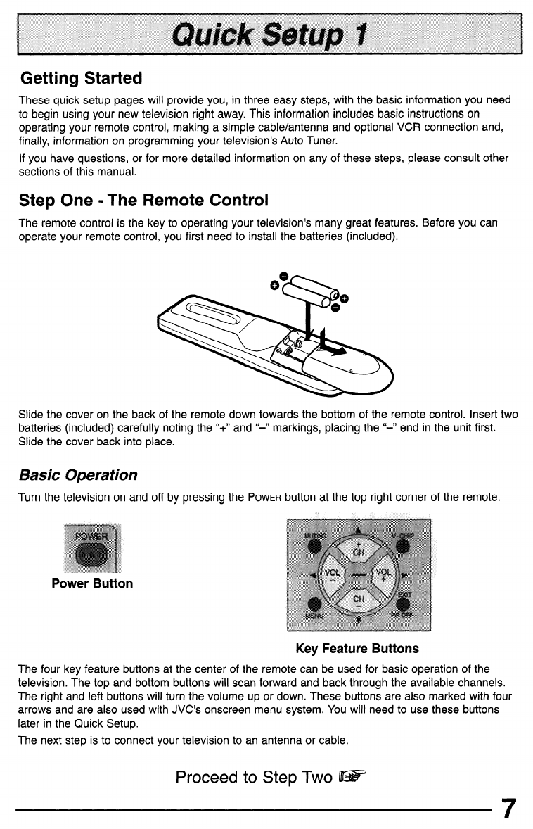
Remote Control Basics. . . . . 17
Changing the Batteries. . . . . 17
Remote Programming . . . . . . . . . . 18
CATV and Satellite Codes. . . . . . . . . 18
VCR Codes, , . . . . , . . . . . , . . . 19
DVD Codes, . . . . . . . . . . . . . . . 20
MENU FUNCTIONS
Using the Guide ............. 21
Plug In Menu
Introduction. ......... 22
Language. .......... 22
Auto Tuner Setup ....... 22
Auto Clock Set. ........ 23
Manual Clock Set ....... 24
Finish. ............. 24
Channel Summary. ........... 25
V-Chip. .................. 26
Set Lock Code. ........ 33
Picture Settings
Tint. .............. 34
Color. ............. 34
Picture ......... 34
Bright ............. 34
Detail ............. 34
Noise Muting ......... 35
Set Video Status ........ 35
Sound Settings
Bass .............. 36
Treble ............. 36
Balance ............ 36
MTS (Multi-channel Sound) 36
General Iterns
On/Off Timer. ......... 37
TV Speaker .......... 38
Audio Out ........... 38
V4 Component-W
V2 Component-In ....... 39
Closed Caption ........ 39
BUTTON FUNCTIONS
Menu. .................. 40
Exit and PIP Off. ............. 40
Display .................. 40
Video Status ............... 41
Sleep Timer. ............... 41
Hyper Surround ............. 41
Muting .................. 41
BBE. ................... 42
lOO+ ................... 42
Return+. ................. 42
Input. .................. 42
VCR Buttons ............... 43
DVD Buttons ............... 43
TV/CATV Switch ............. 43
VCR/DVD Switch ............. 43
Light. .................. 43
PIP (Picture-In-Picture)
Introduction. ......... 44
On/Move. ........... 44
Freeze. ............ 45
Swap. ............. 45
Channel +/-. ......... 45
Source. ............ 45
APPENDICES
Troubleshooting . . . . . . . , . . . . . 46
Warranty . . . . . . . . . . . . . . . . . 47
Authorized Service Centers . , . . . . . 49
Search Codes. , . . . . . . . . . . . . . 50
Specifications. . . , . . . . . . . , . . . 51

Connections
Diagram #I
CABLE or ANTENNA
QLiT
lllustr
*ation of AV-27F8
1) Connect the antenna or cable TV wire from the wall outlet, in to the RF Input of the two-way splitter.
2) Connect an RF cable from the one of the RF Outputs on the splitter, in to the RF Input on the
back of the VCR.
3) Connect an RF cable from the other the RF Output on the splitter, in to the RF Input on the
back of the TV.
4) Connect the yellow video cable out from the VCR’s Video Output, in to the TV’s Video Input
jack, OR connect an S-Video cable from the VCR’s S-Video output, to the TV’s S-Video input.
5) Connect the white audio cable out from the VCR’s Left Audio Output, in to the TV’s Left Audio
Input Jack.
6) Connect the red audio cable out from the VCR’s Right Audio Output, in to the TV’s Right
Audio Input jack.
l
If your VCR is a mono sound unit, it will have only one Audio Out jack. Connect it to the TV’s
Left Audio Input.
l
Please consult your VCR’s owner’s manual for more information on its operation.
11

Connections
Cable and VCR Connections - Continued
Diagram #2
CABLE or ANTENNA
Q.;:T
lllustr
1)
2)
3)
4)
5)
6)
.
.
.
Connect the antenna or cable TV wire from the wail outlet, in to the RF Input of the cable box.
Connect an RF cable from the RF Output of the cable box, in to the RF Input on the back of
the VCR.
Connect an RF cable from the RF Output of the VCR, in to the RF Input on the back of the TV.
Connect the yellow video cable out from the VCR’s Video Output, in to the TV’s Video Input
jack, OR connect an S-Video cable from the VCR’s S-Video output, to the TV’s S-Video input.
Connect the white audio cable out from the VCR’s Left Audio Output, in to the TV’s Left Audio
Input Jack.
Connect the red audio cable out from the VCR’s Right Audio Output, in to the TV’s Right
Audio Input jack.
Please see page 44 for information on using the PIP feature with a Cable Box.
If your VCR is a mono sound unit, it will have only one Audio Out jack. Connect it to the TV’s
Left Audio Input.
Please consult your VCR’s owner’s manual for more information on its operation.
12

Connections
Cable and VCR Connections - Continued
Diagram #3
WALL
CABLE or ANTENNA
OUT
Illustration of AV-27F802
1) Connect the antenna or cable TV wire from the wall outlet, in to the RF Input of the two-way splitter.
2) Connect an RF cable from the one of the RF Outputs on the splitter, in to the cable box RF Input.
3) Connect an RF cable from the Cable Box Output, in to the VCR RF Input.
4) Connect an RF cable from the other the RF Output on the splitter, in to the RF Input on the back of
the TV.
5) Connect the yellow video cable out from the VCR’s Video Output, in to the TV’s Video Input jack, OR
connect an S-Video cable from the VCR’s S-Video output, to the TV’s S-Video input.
6) Connect the white audio cable out from the VCR’s Left Audio Output, in to the TV’s Left Audio Input
jack.
7) Connect the red audio cable out from the VCR’s Right Audio Output, in to the TV’s Right Audio Input
jack.
l
Please see page 44 for information on using the PIP feature with a Cable Box.
l
If your VCR is a mono sound unit, it will have only one Audio Out jack. Connect it to the TV’s
Left Audio Input.
l
Please consult your VCR’s owner’s manual for more information on its operation.
13

Connections
Connecting to a DVD player
Illustration of AV27F802
1) Connect Green cable out from DVD player “Y” Component Output, in to TV “Y” Component
Input.
2) Connect Blue cable out from DVD player
“PB”
Component Output, in to TV
“PB”
Component
Input.
3) Connect Red cable out from DVD Player “PR” Component Output, in to TV “PR” Component
Input.
4) Connect White Audio cable out from DVD Left Audio Output, in to TV Left Audio Input 2.
5) Connect Red Audio cable out from DVD Right Audio Output, in to TV Right Audio Input 2.
Green, blue and red are the most common colors for DVD cables. Some models may vary
colors, please consult the user’s manual for your DVD Player for more information.
Be careful not to confuse the red DVD cable with the red audio cable. It is best to complete
one set of connections (DVD or Audio Output) before starting the other to avoid accidentally
switching the cables.
See page 20 for instructions on programming your remote control to operate the basic func-
tions of your DVD player.
AV-32F802 & AW27F802: You may also connect the DVD player to Input 4. If you use Input 4
for the DVD connection, you must set the V4 COMPONENT-IN on the initial Setup Menu to
“YES” for proper display of the DVD signal.
AV-32F702 & AW27F702: If you use Input 2 (Component-In) for the DVD connection, you
must set the V2 COMPONENT-IN on the initial Setup Menu to “YES” for proper display of the
DVD signal.
NOTE: Progressive DVD Players (players with an output scan of 31.5 KHz) will not work prop-
erly with this television.
14

Connections
Connecting to an External Amplifier
illustration of AV27F802
1) Connect the white audio cable from the TV’s Left Audio Output jack to the Amplifier’s Left
Audio Input jack.
2) Connect the red audio cable from the TV’s Right Audio Output jack to the Amplifier’s Right
Audio Input jack.
l
See also “TV Speaker” and “Audio Out” on page 38 for more information on using external
speakers.
Connecting to a Camcorder
DER
Illustration of AW27F802
1) Connect the yellow video cable out from the Camcorder’s Video Output, in to the TV’s Video
Input jack, OR connect an S-Video cable from the Camcorder’s S-Video output, to the TV’s
S-Video Input.
2) Connect the white audio cable out from the Camcorder’s Left Audio Output, in to the TV’s Left
Audio Input jack.
3) Connect the red audio cable out from the Camcorder’s Right Audio Output, in to the TV’s
Right Audio Input jack.
l
If your Camcorder is a mono sound model it will have only one audio jack. Connect it to the
TV’s Left Audio jack.
15

Connections
Connecting to JVC AV Compu Link
AV Compu Link EX compatible
ka? or ma P&w-
Illustration of AV-27F802
To Connect: Plug one end of the AV Compu Link cable into the AV Compu Link input on your VCR,
DVD, or other Compu Link device. Plug the other end of the AV Compu Link cable into the AV Compu
Link input at the rear of the television.
NOTES:
* In order for the VCR playback to begin automatica& the recording tabs must be removed from the
VHS tape. If the tab is in place, automatic switching will occur when you push the VCR’SPLAYbutton.
l The AV Compu Link cab/e has a ma/e 3.5 mm (mono) plug on each end.
l If your JVC-brand VCR has “A Code/B Code Remote Control Switching” (see your VCR’s instruction
book), using VCR A Code will switch the TV to input 1.
l Toconnect a JVC HiFi receiver or amplifier for a completely automated home theater; see the HiFi’s
connection instructions for detailed connection information.
l AV COMPU LINK EX is compatible with the following receivers: RX-664v RX-665v RX-668VBK,
RX-774v RX-778VBK, RX-884v RX-888VBK, RX-1024v RX-1028VBK, and later receiver models.
16

Remote Control
Remote Control Basics
l Before you can operate the remote control, you must first install
the batteries (included). See “Changing the Batteries” at the
bottom of this page for instructions. (For an illustration, please see
page 7.)
l Press the POWERbutton to turn the television on or off.
l Make sure the TVKATV switch is set to TV. Move the switch to
CATV only if you need to operate a cable box.
l Slide the VCR/DVD selector switch to VCR to control a VCR,
slide to DVD to control a DVD player. Please see pages 18 to
20 for instructions on programming your remote control to
operate a Cable box, VCR or DVD player.
l Press the CH+ and CH- buttons to scan through the channels.
Tap the CH+ or CH- button to move through the channels one
channel at a time.
l To move rapidly through the channels using JVC’s Hyperscan
feature, press and hold CH+ or CH-. The channels will zip by at
a rate of five channels per second.
l Press
VOL+
or
VOL
- to raise or lower the volume. An indicator
bar will appear onscreen to show you the television volume
level.
l The CH+/- and
VOL+/-
buttons are also used to navigate JVC’s
onscreen menu system.
l You can directly access specific channels using the 1O-key pad.
l For more information on remote control button features, see
pages 40 to 45. For information on using the onscreen menus,
see page 21.
Notes: Remote control model RM-C301G is shown at the left.
A different model remote control may have come with your
television.
Changing the Batteries
Push down on the remote’s back cover and slide towards the bottom to remove it.
Insert two AA batteries (supplied), carefully noting the I’+” and “-‘I markings on the batteries and on
the remote control. To avoid a potential short circuit, insert the “-‘I end first. Be sure to use only size
AA batteries.
When batteries are installed, slide the cover back into place (until it clicks into position).
l
If the remote control acts erratically, replace the batteries. Typical battery life is six months to one
year. We recommend using alkaline batteries for longer battery life.
Whenyou change the batteries, try to complete the task withinthree minutes. Ifyou take longer than three
minutes, the remote control codes for-yourVCR, DVD,andor Cable Box may have to be reset (seepage 18-20).
17

Remote Programming
Setting the CATV,VCR and DVD Codes
Cable Box or Satellite codes
The remote control is programmed with CATV and/or Satellite codes for power on, power off,
channel up, channel down, and IO key operation.
1) Find the CATVISatellite brand from the list of codes shown below.
2) Slide the 2-way selector switch to “CATV”.
3) Press and hold down the
DISPLAY
button.
4) With the
DISPLAY
button held down, enter the first code number listed using the 10 key pad.
5)
Release the
DISPLAY
button.
6) Confirm the operation of the Cable Box/Satellite receiver.
l
If your CATV or Satellite box does not respond to the first code, try the others listed. If it does not
respon d to any code, trv the Search Codes Function. on oaae 50.
Q , 3 - I- s--.w- --.
1 ABC 1024 1 Puser 1032
(
zitizen I 022,051 I Rectal -
058, 064, 040, Express VU 100,113
Curtis 058,059 041, 042, 045, G.E. 106
Diamond (pd n13 n3lz 1 068
L-r, ““CL, “LQ
Cl
Regency ~ U.I.
034 108
Eagle u29 Rembrandt 037, 032, 051, Gradliente 112
Eastern 034 038 HitacIt,
.ki
4nA
444
1
GC Branc
I
-em A#-4
u&d, u3 I
. ,
1 IUL), III
Samsung 051
Gemini 022,043 - HNS (Hughes) 104
Generallnst._..._...- Scientific Atlanta 057, 058, 059
rument
n&i
n34
n3.c; 1-- Panasonic 105
I ---I -- -1---9 I 0, .“,“I. 051,047
-
021, 022, 057, Sprucer 051,056 Philips 102,103
023 - Primestar 108
Hamlin - Stargate 032,051
040, 041, 042, - Proscan 106,109,llO
Hitachi 049,024 Teleview 047,051 106,109,llO
107
I
1026, 027, 020, j 3L’V’arK
1 Jerrold 1065,024,025, t
Texsm n
Magnavox
Memorex
Movietime
-033 Universal 022,032
030 Videoway 052
032,051 Viewstar 029,030
Oak
Panasonic
Paragon
Philips
039,037,048 Zenith 063,046
055, 056, 060, Zenith/Drake 046
071 Satellite
063
028, 029, 030,
052, 053, 031,
069
Pioneer 047,062
Pulsar 051,032

Remote Programming
VCR codes
The remote control is programmed with VCR codes for power on, power off, play, stop, fast-forward,
rewind, pause, record, channel up, and channel down operation.
1) Find the VCR brand from the list of codes shown below.
2) Slide the first 2-way selector switch to “TV” and the other 2-way selector switch to ‘VCR”.
3) Press and hold down the
DISPLAY
button.
4) With the
DISPLAY
button held down, enter the first code number Jistedwith the 10 key pad.
5) Release the
DISPLAY
button.
6) Confirm the operation of the VCR.
l
If your VCR does not respond to the first code, try the others listed. If it does not respond to any
code, try the Search Codes Function, on page 50.
l
Somemanufacturer’sVCR’smaynotrespondto theTV/VCRbutton,evenifotherbuttonswork properly.
l
To record, hold down the
REC
button on the remote and press
PLAY.
1 Admiral ] 035 _I Marantz 1003,004,005 1 Samsung I 037, 060, 062,
033,089 I
027,032,095 Marta 064
Akai p
029, 072, 073, Memorex 024,067 Samtron 089
074 MGA 038, 040, 047, Sansui 003, 026, 020,
Audio Dynamic 003,005 048,041,042 , 052
Bell & Howell 1063, 071 1 Minolta 1058,045,093 1 Sanyo 1063,067, 091,
^-* 1
Broksonic 020,026,094 Mitsubishi 038, 040, 047,
U/l
Canon 023,025 048. 041. 042 Scott 059, 060, 062,
CCE 043 0;
-
Citizen 064 Multitech v-r,) vL,, vvL I020
’ NEC I I
Craig 063,029,064 fb,
CurtisMathes 045, 024, 027,
093 Olympic 1u24,023 ! 1001 I
I
1 Optimus 1028, 021, 035, 1 Shintom 1075 I
DBX
Dimensia
Emerson
Fisher
Sharp I 035,036,080, 1
et--
003,004,005 WIIUII
UOU
045,093 Panasonic 023, 024, 021, Signature 2000 027, 035
022
043, 026, 077, - Singer 075
Pmnfw
024, 058, 045,
020,076 063, 003, 004, Sony 028, 029, 030,
005,093 053,054,055
063, 066, 067, -
Pmtay fXR nnr; nAEi
sv 2000 027
I
1061, 025, 042, 1 ’ ““““’
I 065, 071, 091 I 031, 023. 024. 1
Philco 027. ’
CI..--L-.-f- 027,081
I-
023; 026,020,
ayrrlprionlc
033,045,024 043 Tashiro 064
037,051,049, Philips 031,023,024, Tatung 003,004,005
G.E.
Go Video
I
1050,089 I I 086 1 Teat 1003. 004.027.
1
4 ---I -- .I I--.
Goldstar 064 Pioneer 023 005
Gradiente 083, 084, 081, Proscan 045, 058, 023, Technics 021, 022,023,
Al. A-1 -*a i
Quasar
Radio Shack
021, 022,023,
024
t-
033, 024, 063,
036, 067, 040,
027
RCA
Realistic
033, 045, 058,
023,024,031,
046, 059, 060,
083, 084, 085,
087.093
024, 063, 036,
067,040,027
1osnroa
VectorResearch
Yamaha
Zenith
WY,
U46, U7Y
005
035, 036, 067,
044,064
063, 003, 004,
005
044, 082, 064,
094
19

Remote Programming
DVD codes
The remote control is programmed with DVD codes for power on, power off, play, stop,
fast-forward, rewind, previous chapter, next chapter, tray open/close, and still/pause operation.
1) Find the DVD player brand from the list of codes shown below.
2) Slide the first 2-way selector switch to “TV” and the other 2-way selector switch to “DVD”.
3) Press and hold down the
DISPLAY
button.
4) With the
DISPLAY
button held down, enter the first code number listed with the 10 key pad.
5)
Release the
DISPLAY
button.
6) Confirm the operation of the DVD player.
l
If your DVD player does not respond to the first code, try the others listed. If it does not respond
to any code, try the Search Codes Function, on page 50.
l
After you program your remote, some DVD buttons may not work properly. If some buttons do not
work properly, use the remote control which came with your DVD player.
20
This manual suits for next models
5
Table of contents
Other JVC TV manuals

JVC
JVC AV-21CN14 User manual

JVC
JVC AV-14F33 User manual

JVC
JVC AV28BT5ENS User manual

JVC
JVC AV-14F7 User manual

JVC
JVC AV-N29220 User manual

JVC
JVC AV-25PX User manual

JVC
JVC AV-28BH8EPB User manual

JVC
JVC HD-ILA TV HD-65S80DDU User manual

JVC
JVC InteriArt LT-30E45SU User manual

JVC
JVC C-20210/S User manual

JVC
JVC AV-14F702 User manual

JVC
JVC AV 27050 User manual

JVC
JVC AV-14F43, AV-20N43, AV-21D43 User manual

JVC
JVC AV32X10EUS User manual

JVC
JVC AV-14F114/B User manual

JVC
JVC 50050690 User manual

JVC
JVC AV-28R4SK User manual

JVC
JVC LT-32EX177 User manual

JVC
JVC AV-32S565 Series User manual

JVC
JVC LT-26DY8ZG User manual