No.51968
V32R25EKS
V32R250EKS
8
AV32R25EKS / AV32R250EKS
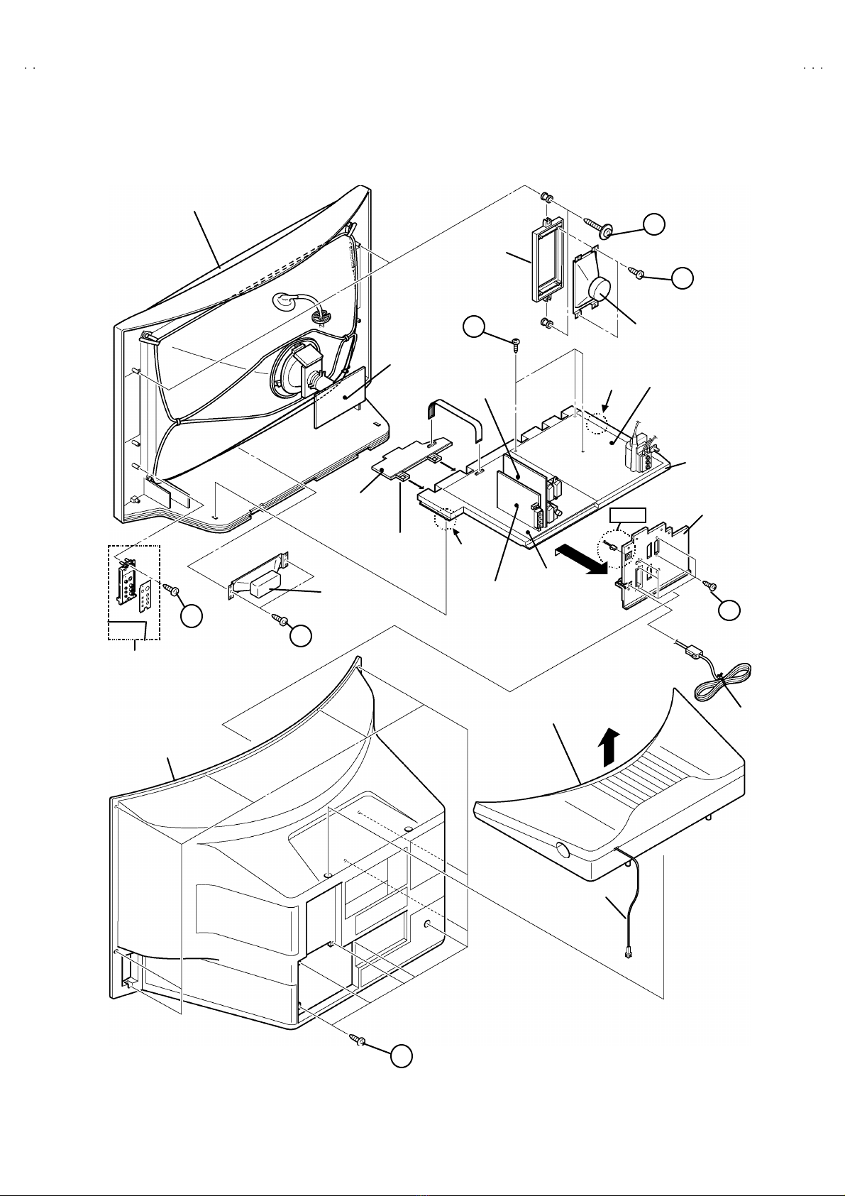
DISASSEMBLY PROCEDURE
REMOVING TH E SUB WOOFER UNIT & THE REAR
COVER
1. Unp lu g t he po we r c or d.
2. Remove the SUB WO OFER CORD from the AV TERMINAL
BOA RD.
3. Pu ll up th e S UB WOO FER UNI T on th e top of th e rear c over
up war d.
4. Remove the 13 screws marked A as s hown in t he Fig. 4.
5. W ithdr a w t he r ear co ver to wa rd you .
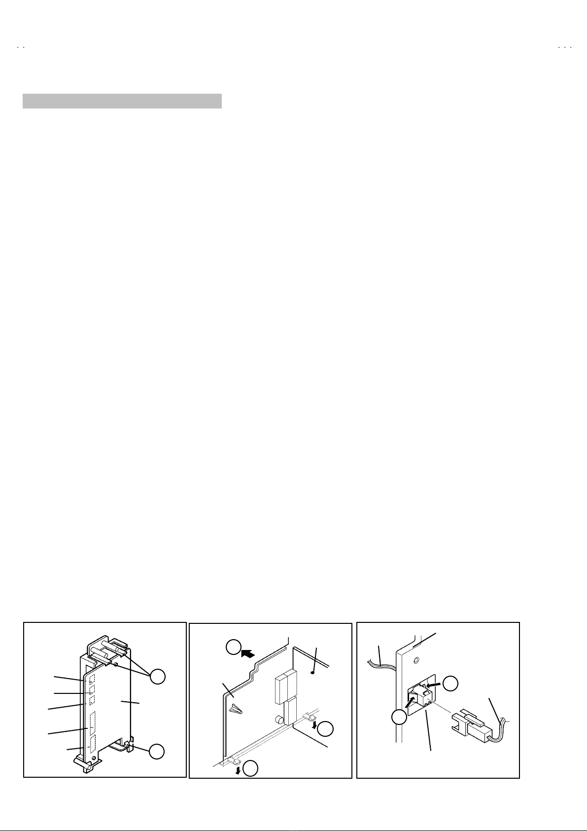
REMOVING T HE SIDE CONTROL JACK ASSEMBLY
"After removing the rear cover.
1. Rem ove th e scr ew m arked Bas sh ow n in the Fig.1 .
2. W hil e sl ight ly r aise th e si d e c ontr o l j ack asse mb ly, r emove th e 2
claws under the side control jac k assembly.
3. Disc onn ect th e c onn ecto r “SR ”, “ SL”, “ S”, “F” and “CN016” as
shown in Fig. 5.
REMOVING T HE SIDE CONTROL PWB
"Af ter r emovi ng th e r e ar cover an d si d e co ntr ol j ac k ass em bly.
1. Remove th e 3 claws Cfrom back side of the side control jack
asse mb l y as s hown i n Fi g. 5.
2. Pu ll out the SI DE CONTRO L PW B .
REMOVING T HE CHASSIS
"After removing the rear cover.
1. Sl ight ly r aise th e bo th si de s of th e c hassis by h and and r e mo ve
th e t w o cl aws u nd er th e b oth si d es of the ch assis fr om t he fr o nt
cab i net .
2. W ithdr a w t he chass is backwa rd .
(If necess ary, take off the wire clamp, connectors etc.)
REMOVING T HE POWER & DEF. PWB
"After removing the chassis.
1. Remove t he 3 screws mar ked Da s sh ow n in Fig. 4.
2. Remove t he PO WER & DEF. PWB upper.
(If necess ary, take off the wire clamp, connectors etc.)
REMOVING T HE CENTER SPEAKER
"After removing the rear cover and chas sis.
1. Remove t he 2 screws marked Eas sh own in F ig. 4.
2. Remove th e ce nte r spea ker . I f n ecess ar y, d eta ch th e c ables .
REMOVING T HE SIDE SPEAKER
"After removing the rear cover.
1. Remove t he 2 screws marked F, and r emove th e sp eake r h ol der
as s h own in Fig. 4.
NOTE : When r emoving th e screws m arked Fof t he sp eak er h olde r
remove t he lo wer side screw fir st, an d t hen remove th e
up per one .
2. Remove the 2 screws Gattac hing the speaker.
3. Fol low th e s am e st eps wh en r emovi ng th e oth er ha nd spe ake r.
REMOVING T HE AV TERMINAL BOARD
"After removing the rear cover.
1. Remove th e 5 screws mar ked H as shown i n t he Fig . 4 .
2. Remove t he 2 cla ws marked Iun der th e CH A SSI S as s ho wn in
Fig. 6.
3. Remove the AV TERMINAL BOARD slightly in the direction of
arrow Jas shown in Fig. 6.
4. After removing the craw Kon t he con nect or f or SUB W O OFER,
pu ll out th e co nn ecto r f or SUB W OOFER. ( Fig. 7)
CHECKING THE PW BOARD
To ch eck the b ack side of th e PW B oar d.
1) Pull out the chassis . (Refer to REMOVING THE CHASSIS).
2) Erect the c hassis vertically so that you c an easily check the
b ack si de of th e PW B oar d.
[CAUTION]
"When erec ting the chassis, be careful so that there will be no
con tact in g wi th ot her PW Boar d.
"Be for e tur n in g on po wer , ma ke sur e t ha t the w ire co nn ecto r i s
pr op erly con nec ted .
"W hen co ndu cti ng a ch eck with p ower su ppl ied , b e sur e to c onfi rm
th at t he CRT E ARTH W I RE (B RA IDED AS S’Y) i s co nnected t o
th e CRT SOC KE T PW b oar d.
WIRE CLAMPING AND CABLE TYING
1. Be sure t o clamp the wire.
2. Never r emo ve th e c abl e tie use d f or tying th e w ire s to ge the r.
Sh oul d it be in adve rt ent ly r em ove d, b e su r e to tie th e wir es wit h
a n ew c able ti e.
SR
Connector
C
SI DE
C ONT RO L
PWB
Fig. 5
SL
S
F
CN016
(Back view)
C
AV SW PW B
I
J
I
Fig. 6
AV TERMINAL
BOARD
Fig. 7
WO OFER
CORD
K
K
AV TERMINAL
BOARD
CONNECT OR for
SUB WOOFER
SUB WOOFER
CORD
www.freeservicemanuals.info
Global electronic heritage manuals