JVC AV 14F704 User manual

COLOR TELEVISION
AV-14F704
No. 52130
2003/05
COPYRIGHT © 2003 VICTOR COMPANY OF JAPAN, LTD.
AV-14F704
SERVICE MANUAL
2
13
78
0
9
456
CH
CH
VOL VOL
2
13
78
0
9
456
CH
CH
VOL VOL
CONTENTS
qSPECIFICATIONS .............................................................................................................................................. 2
qOPERATING INSTRUCTIONS (APPENDIX)
qSAFETY PRECAUTIONS .................................................................................................................................. 3
qSPECIFIC SERVICE INSTRUCTIONS .............................................................................................................. 4
qSERVICE ADJUSTMENTS ................................................................................................................................ 8
qGUIDE FOR REPAIRING ................................................................................................................................. 13
qSTANDARD CIRCUIT DIAGRAM ................................................................................................................... 2-1
qPARTS LIST ..................................................................................................................................................... 19

2
AV-14F704
No. 52130
SPECIFICATIONS
TELEVISION
Picture Tube: 14” (measured diagonally)
Color System: NTSC
TV RF System: US System M
Tuner Type: 181 Channel, Quartz PLL Frequency Synthesized
Receiving Channels: VHF 2-13
UHF 14-69
CATV 01-97 (5A)-(A-3)
98-99 (A-2)-(A-1)
14-22 (A)-(I)
23-36 (J)-(W)
37-65 (AA)-(FFF)
66-125 (GGG)-(125)
Intermediate Frequency: Picture (FP) : 45.75 MHz
Sound (FS) : 41.25 MHz
FP-FS : 4.50 MHz
Antenna Input: VHF/UHF/CATV In 75 ohms coaxial, F-Type Connector
Speaker: 1-5/8” (4 cm) x 2-13/16” (7 cm), 8 ohms x 2
Audio Output Power: 2.5 W + 2.5 W
GENERAL
Power Source: 120 V AC, 60 Hz
Power Consumption: 80 Watts
Dimensions(W x H x D): 17-1/8” (432 mm) x 13-5/8” (344.5 mm) x 15-1/2” (393.5 mm)
Weight: 26.4 Ibs/12 kg
Video/Audio Inputs: Component input
Y input: 1.0 Vp-p, 75 ohm (RCA pin jack)
Pb, Pr input : 0.7 Vp-p, 75 ohm (RCA pin jack)
S-Video input
Y input: 1.0 Vp-p, 75 ohm
C input: 0.3 Vp-p, 75 ohm
Video input: 1.0 Vp-p, 75 ohm (RCA pin jack)
Audio input: -8dB, 47 kohm (RCA pin jack)
Headphone Jack: 3.5 mm mini-jack
Storage Temperature -20 ºC ~ 60 ºC
Operating Temperature 5 ºC ~ 40 ºC
Accessories:
Remote Control X 1
Batteries (UM-3) X 2
Design & specification are subject to change without notice.

No. 52130 3
AV-14F704
Please include the following informations when you order parts. (Particularly the VERSION LETTER.)
1. MODEL NUMBER and VERSION LETTER
The MODEL NUMBER can be found on the back of each product and the VERSION LETTER can be found at the end of the SERIAL
NUMBER.
2. PART NO. and DESCRIPTION
You can find it in your SERVICE MANUAL.
SAFETY PRECAUTIONS
SERVICING NOTICES ON CHECKING
1. KEEP THE NOTICES
As for the places which need special attentions, they are
indicated with the labels or seals on the cabinet, chassis and
parts. Make sure to keep the indications and notices in the
operation manual.
2. AVOID AN ELECTRIC SHOCK
There is a high voltage part inside. Avoid an electric shock
while the electric current is flowing.
3. USE THE DESIGNATED PARTS
The parts in this equipment have the specific characters of
incombustibility and withstand voltage for safety. Therefore,
the part which is replaced should be used the part which has
the same character.
Especially as to the important parts for safety which is
indicated in the circuit diagram or the table of parts as a !
mark, the designated parts must be used.
4. PUT PARTS AND WIRES IN THE ORIGINAL
POSITION AFTER ASSEMBLING OR WIRING
There are parts which use the insulation material such as a
tube or tape for safety, or which are assembled in the condition
that these do not contact with the printed board. The inside
wiring is designed not to get closer to the pyrogenic parts and
high voltage parts.
Therefore, put these parts in the original positions.
5. TAKE CARE TO DEAL WITH THE
CATHODE-RAY TUBE
In the condition that an explosion-proof cathoderay tube is set
in this equipment, safety is secured against implosion.
However, when removing it or serving from backward, it is
dangerous to give a shock. Take enough care to deal with it.
6. AVOID AN X-RAY
Safety is secured against an X-ray by considering about the
cathode-ray tube and the high voltage peripheral circuit, etc.
Therefore, when repairing the high voltage peripheral circuit,
use the designated parts and make sure not modify the
circuit.
Repairing except indicates causes rising of high voltage, and
it emits an X-ray from the cathoderay tube.
7. PERFORM A SAFETY CHECK AFTER SERVICING
Confirm that the screws, parts and wiring which were
removed in order to service are put in the original positions, or
whether there are the portions which are deteriorated around
the serviced places serviced or not. Check the insulation
between the antenna terminal or external metal and the AC
cord plug blades. And be sure the safety of that.
(INSULATION CHECK PROCEDURE)
1. Unplug the plug from the AC outlet.
2. Remove the antenna terminal on TV and turn on the TV.
3. Insulation resistance between the cord plug terminals and
the eternal exposure metal [Note 2] should be more than
1M ohm by using the 500V insulation resistance meter
[Note 1].
4. If the insulation resistance is less than 1M ohm, the
inspection repair should be required.
[Note 1]
If you have not the 500V insulation resistance meter, use a
Tester.
[Note 2]
External exposure metal:Antenna terminal
Earphone jack
HOW TO ORDER PARTS
Inferior silicon grease can damage IC's and transistors.
When replacing an IC's or transistors, use only specified silicon grease (YG6260M).
Remove all old silicon before applying new silicon.
IMPORTANT

4
AV-14F704
No. 52130
DISASSEMBLY INSTRUCTIONS
1. REMOVAL OF ANODE CAP
Read the following NOTED items before starting work.
* After turning the power off there might still be a potential voltage
that is very dangerous. When removing the Anode Cap, make
sure to discharge the Anode Cap's potential voltage.
* Do not use pliers to loosen or tighten the Anode Cap terminal,
this may cause the spring to be damaged.
REMOVAL
1. Follow the steps as follows to discharge the Anode Cap.
(Refer to Fig. 1-1.)
Connect one end of an Alligator Clip to the metal part of a flat-
blade screwdriver and the other end to ground.
While holding the plastic part of the insulated Screwdriver, touch
the support of the Anode with the tip of the Screwdriver.
A cracking noise will be heard as the voltage is discharged.
GND on the CRT
Screwdriver
Alligator Clip
Support
CRT
GND on the CRT
Fig. 1-1
2. Flip up the sides of the Rubber Cap in the direction of the arrow
and remove one side of the support.
(Refer to Fig. 1-2.)
Fig. 1-2
Rubber Cap
CRT
Support
3. After one side is removed, pull in the opposite direction to
remove the other.
NOTE
Take care not to damage the Rubber Cap.
INSTALLATION
1. Clean the spot where the cap was located with a small amount of
alcohol. (Refer to Fig. 1-3.)
NOTE
Confirm that there is no dirt, dust, etc. at the spot where the cap
was located.
4. Insert one end of the Anode Support into the anode button, then
the other as shown in Fig. 1-5.
Location of Anode Cap
Fig. 1-3
2. Arrange the wire of the Anode Cap and make sure the wire is not
twisted.
3. Turn over the Rubber Cap. (Refer to Fig. 1-4.)
Fig. 1-4
5. Confirm that the Support is securely connected.
6. Put on the Rubber Cap without moving any parts.
Fig. 1-5
SPECIFIC SERVICE INSTRUCTIONS
CRT Support

No. 52130 5
AV-14F704
2. REMOVAL AND INSTALLATION OF
FLAT PACKAGE IC
REMOVAL
1. Put the Masking Tape (cotton tape) around the Flat Package IC
to protect other parts from any damage.
(Refer to Fig. 2-1.)
NOTE
Masking is carried out on all the parts located within
10 mm distance from IC leads.
Masking Tape
(Cotton Tape)
IC
Fig. 2-1
2. Heat the IC leads using a blower type IC desoldering machine.
(Refer to Fig. 2-2.)
NOTE
Do not add the rotating and the back and forth directions force
on the IC, until IC can move back and forth easily after
desoldering the IC leads completely.
Fig. 2-1
Fig. 2-2
Blower type IC
desoldering machine
IC
3. When IC starts moving back and forth easily after desoldering
completely, pickup the corner of the IC using a tweezers and
remove the IC by moving with the IC desoldering machine.
(Refer to Fig. 2-3.)
NOTE
Some ICs on the PCB are affixed with glue, so be careful not
to break or damage the foil of each IC leads or solder lands
under the IC when removing it.
Fig. 2-3
Blower type IC
desoldering machine
Tweezers
IC
4. Peel off the Masking Tape.
5. Absorb the solder left on the pattern using the Braided Shield
Wire. (Refer to Fig. 2-4.)
NOTE
Do not move the Braided Shield Wire in the vertical direction
towards the IC pattern.
Fig. 2-4
Braided Shield Wire
Soldering Iron
IC pattern

6
AV-14F704
No. 52130
INSTALLATION
1. Take care of the polarity of new IC and then install the new IC
fitting on the printed circuit pattern. Then solder each lead on the
diagonal positions of IC temporarily.
(Refer to Fig. 2-5.)
Fig. 2-5
Soldering Iron
Solder temporarily Solder temporarily
2. Supply the solder from the upper position of IC leads sliding to
the lower position of the IC leads.
(Refer to Fig. 2-6.)
Fig. 2-6
Solder
IC
Soldering Iron
Supply soldering
from upper position
to lower position
3. Absorb the solder left on the lead using the Braided Shield Wire.
(Refer to Fig. 2-7.)
NOTE
Do not absorb the solder to excess.
Soldering Iron
IC
Braided Shield Wire
Fig. 2-7
4. When bridge-soldering between terminals and/or the soldering
amount are not enough, resolder using a Thintip Soldering Iron.
(Refer to Fig. 2-8.)
Fig. 2-8
Thin-tip Soldering Iron
IC
5. Finally, confirm the soldering status on four sides of the IC using
a magnifying glass.
Confirm that no abnormality is found on the soldering position
and installation position of the parts around the IC. If some
abnormality is found, correct by resoldering.
NOTE
When the IC leads are bent during soldering and/or repairing,
do not repair the bending of leads. If the bending of leads are
repaired, the pattern may be damaged. So, be always sure to
replace the IC in this case.

No. 52130 7
AV-14F704
SERVICE MODE LIST
This unit provided with the following SERVICE MODES so you can repair, examine and adjust easily.
To enter the Service Mode, press both set key and remote control key for more than 1 second.
Set Key Remocon Key Operations
VOL. (-) MIN
VOL. (-) MIN
VOL. (-) MIN
VOL. (-) MIN
VOL. (-) MIN
VOL. (-) MIN
0
1
3
6
8
9
Releasing of V-CHIP PASSWORD.
Initialization of the factory.
NOTE: Do not use this for the normal servicing.
If you set a factory initialization, the memories are reset such as the channel setting, and
the POWER ON total hours.
Remocon format selection. (JVC format →NEC format)
NOTE: Supplied remocon can not be operated at NEC format.
(The “N” is always displayed on the monitor.)
Do not use this for the normal servicing.
POWER ON total hours is displayed on the screen.
Refer to the “CONFIRMATION OF HOURS USED”.
Can be checked of the INITIAL DATA of MEMORY IC.
Refer to the “WHEN REPLACING EEPROM (MEMORY) IC”.
Writing of EEPROM initial data.
NOTE: Do not use this for the normal servicing.
Display of the Adjustment MENU on the screen.
Refer to the “ELECTRICAL ADJUSTMENT” (On-Screen Display Adjustment).
CONFIRMATION OF HOURS USED
POWER ON total hours can be checked on the screen.
Total hours are displayed in 16 system of notation.
NOTE:If you set a factory initialization, the total hours is reset
to “0”.
1. Set the VOLUME to minimum.
2. Press both VOL. DOWN button on the set and Channel button
(6) on the remote control for more than 1 second.
3. After the confirmation of using hours, turn off the power.
Initial setting content of MEMORY IC.
POWER ON total hours.
= (16 x 16 x 16 x thousands digit value)
+ (16 x 16 x hundreds digit value)
+ (16 x tens digit value)
+ (ones digit value)
ADDRESS DATA
INIT 00 D0
CRT ON 0010
FIG. 1
WHEN REPLACING EEPROM (MEMORY) IC
If a service repair is undertaken where it has been required to change the MEMORY IC, the following steps should be taken to
ensure correct data settings while making reference to TABLE 1.
NOTE: No need setting for after INI 1F due to the adjustment value.
1. Enter DATA SET mode by setting VOLUME to minimum.
2. Press both VOL. DOWN button on the set and Channel button (6) on the remote control for more than 1 second.
ADDRESS and DATA should appear as FIG 1.
3. ADDRESS is now selected and should “blink”. Using the VOL. +/- button on the remote, step through the ADDRESS until required
ADDRESS to be changed is reached.
4. Press ENTER to select DATA. When DATA is selected, it will “blink”.
5. Again, step through the DATA using VOL. +/- button until required DATA value has been selected.
6. Pressing ENTER will take you back to ADDRESS for further selection if necessary.
7. Repeat steps 3 to 6 until all data has been checked.
8. When satisfied correct DATA has been entered, turn POWER off (return to STANDBY MODE) to finish DATA input.
After the data input, set to the initializing of shipping.
9. Turn on the POWER.
10. Press both VOL. DOWN button on the set and Channel button (1) on the remote control for more than 1 second.
11. After the finishing of the initializing of shipping, the unit will turn off automatically.
The unit will now have the correct DATA for the new MEMORY IC.
D0 E8 02 64 5E B3 24 37 39 AC
+0 +1 +2 +3 +4 +5 +6 +7 +8 +9 +A +B +C +D +E +F
INI
50 00 00 00 16 06 99 28 0F10 00 0D C2 A6 88 43 00
00 00 04 40 40 40 7F
Table 1

8
AV-14F704
No. 52130
ELECTRICAL ADJUSTMENTS
1. ADJUSTMENT PROCEDURE
Read and perform these adjustments when repairing the circuits or
replacing electrical parts or PCB assemblies.
CAUTION
•Use an isolation transformer when performing any service on this
chassis.
•Before removing the anode cap, discharge electricity because it
contains high voltage.
• When removing a PCB or related component, after unfastening
or changing a wire, be sure to put the wire back in its original
position.
•When you exchange IC and Transistor for a heat sink, apply the
silicon grease on the contact section of the heat sink. Before
applying new silicon grease, remove all the old silicon grease.
(Old grease may cause damages to the IC and Transistor.)
Prepare the following measurement tools for electrical
adjustments.
1. Oscilloscope
2. Digital Voltmeter
3. Multi-Sound Signal Generator
4. Pattern Generator
On-Screen Display Adjustment
1. In the condition of NO indication on the screen.
Press the VOL. DOWN button on the set and the Channel button
(9) on the remote control for more than 1 second to appear the
adjustment mode on the screen as shown in Fig. 1-1.
Fig. 1-1
2. BASIC ADJUSTMENTS
2-1: CONSTANT VOLTAGE
1. Place the set with Aging Test for more than 5 minutes.
2. Set condition is AV MODE without signal.
3. Connect the digital voltmeter to the TP003.
4. Adjust the VR502 until the DC voltage is 115 ± 1V.
2-2: CUT OFF
1. Place the set with Aging Test for more than 15 minutes.
2. Activate the adjustment mode display of Fig. 1-1 and press the
channel button (01) on the remote control to select “CUT OFF”.
3. Adjust the Screen Volume until a dim raster is obtained.
2-3: WHITE BALANCE
NOTE: Adjust after performing CUT OFF adjustment.
1. Place the set with Aging Test for more than 10 minutes.
2. Receive the gray scale pattern from the Pattern Generator.
3. Using the remote control, set the brightness and contrast to
normal position.
4. Activate the adjustment mode display of Fig. 1-1 and press the
channel button (12) on the remote control to select “R. BIAS”.
5. Press the CH. UP/DOWN button on the remote control toselect
the “R. BIAS”, “G. BIAS”, “B. BIAS”, “B. DRIVE” or “G. DRIVE”.
6. Adjust the VOL. UP/DOWN button on the remote control to
whiten the R. BIAS, G. BIAS, B. BIAS, B. DRIVE, and G. DRIVE
at each step tone sections equally.
7. Perform the above adjustments 5 and 6 until the white color is
looked like a white.
2-4: FOCUS
1. Receive the monoscope pattern.
2. Turn the Focus Volume fully counterclockwise once.
3. Adjust the Focus Volume until picture is distinct.
2-5: HORIZONTAL POSITION
1. Receive the monoscope pattern.
2. Using the remote control, set the brightness and contrast to
normal position.
3. Activate the adjustment mode display of Fig. 1-1 and press the
channel button (03) on the remote control to select "H.PHASE".
4. Press the VOL. UP/DOWN button on the remote control until the
SHIFT quantity of the OVER SCAN on right and left becomes
minimum.
2-6: VERTICAL POSITION
1. Receive the monoscope pattern.
2. Using the remote control, set the brightness and contrast to
normal position.
3. Adjust the VR401 until the horizontal line becomes fit to the
notch of the shadow mask.
TV
00 OSD 35
3. Use the Channel UP/DOWN button or Channel button (0-9) on
the remote control to select the options shown in Fig. 1-2.
4. Press the MENU button on the remote control to end the
adjustments.
Fig. 1-2
NO.
00
01
02
03
04
05
06
07
08
09
10
11
12
13
14
15
16
17
FUNCTION
OSD H
CUT OFF
H. VCO
H. PHASE
AFC GAIN
V. SHIFT
H. SIZE
V. SIZE
V. LINEARITY
VS CORRECTION
DRIVE R
DRIVE B
R CUT OFF
G CUT OFF
B CUT OFF
BRIGHT MAX
BRIGHT CENT
BRIGHT MIN
NO.
18
19
20
21
22
23
24
25
26
27
28
29
30
31
32
33
34
35
FUNCTION
CONTRAST MAX
CONTRAST CENT
CONTRAST MIN
COLOR MAX
COLOR CENT
COLOR MIN
TINT
SHARPNESS
Cb DELAY FINE
Cr DELAY FINE
Cb PEDESTAL ADJ
Cr PEDESTAL ADJ
E/W PARABOLA
E/W CORNER
E/W TRAPEZIUM
LEVEL
SEPARATION1
SEPARATION2
SERVICE ADJUSTMENTS

No. 52130 9
AV-14F704
2-7: VERTICAL SIZE
1. Receive the monoscope pattern.
2. Using the remote control, set the brightness and contrast to
normal position.
3. Activate the adjustment mode display of Fig. 1-1 and press the
channel button (07) on the remote control to select “V. SIZE”.
4. Press the VOL. UP/DOWN button on the remote control until the
SHIFT quantity of the OVER SCAN on upside and downside
becomes 9 ± 2%.
2-8: VERTICAL LINEARITY
NOTE: Adjust after performing adjustments in section 2-7.
After the adjustment of Vertical Linearity, reconfirm the
Vertical Position and Vertical Size adjustments.
1. Receive the monoscope pattern.
2. Using the remote control, set the brightness and contrast to
normal position.
3. Activate the adjustment mode display of Fig. 1-1 and press the
channel button (08) on the remote control to select “V. LIN”.
4. Press the VOL. UP/DOWN button on the remote control until the
SHIFT quantity of the OVER SCAN on upside and downside
becomes minimum.
2-9: LEVEL
1. Receive the VHF HIGH (70dB).
2. Connect the AC voltmeter to the pin 6 of CP101.
3. Activate the adjustment mode display of Fig. 1-1 and press the
channel button (33) on the remote control to select “LEVEL”.
4. Press the VOL. UP/DOWN button on the remote control until the
AC voltmeter is 75 ± 2mV.
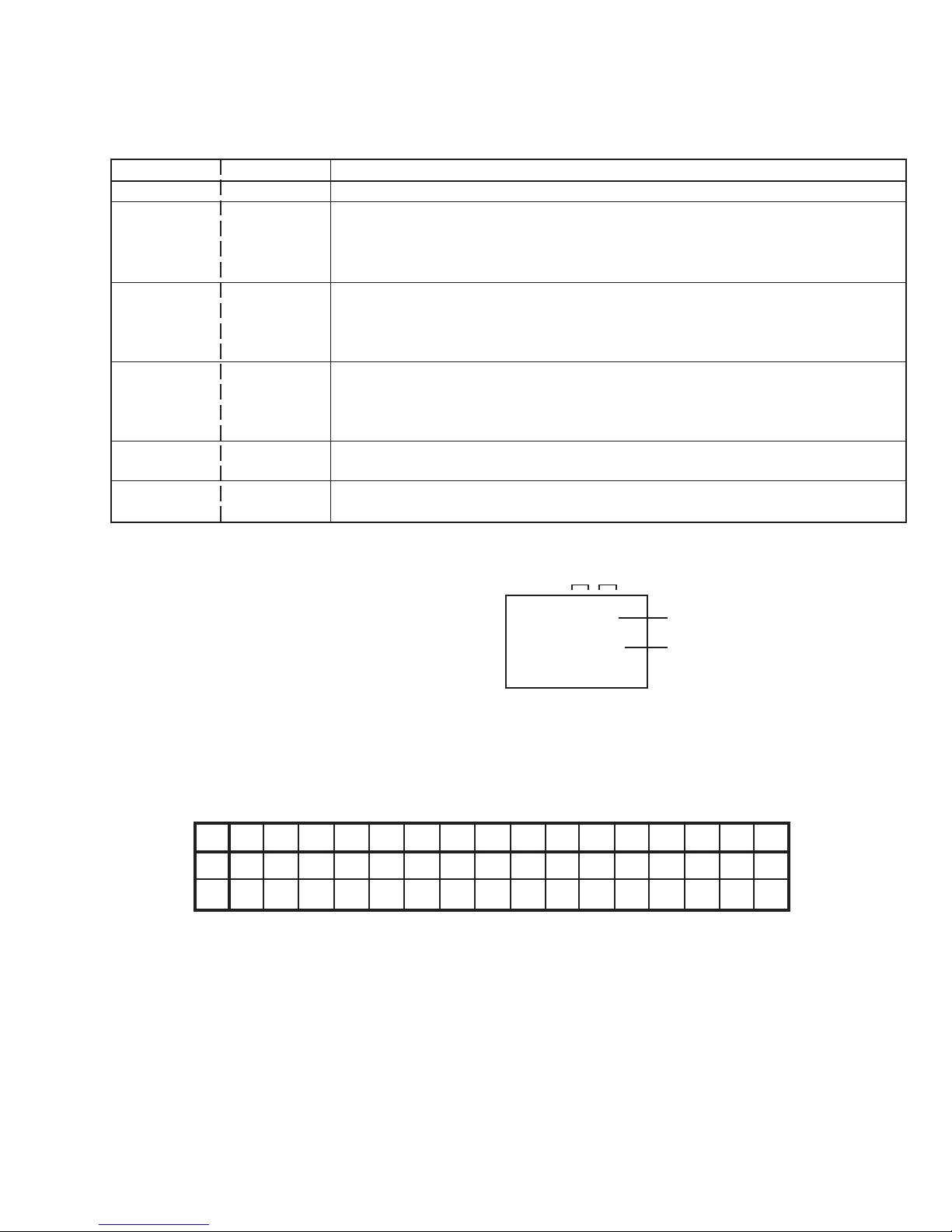
2-10: OSD HORIZONTAL
1. Activate the adjustment mode display of Fig. 1-1.
2. Press the VOL. UP/DOWN button on the remote control until the
difference of A and B becomes minimum.
(Refer to Fig. 2-1)
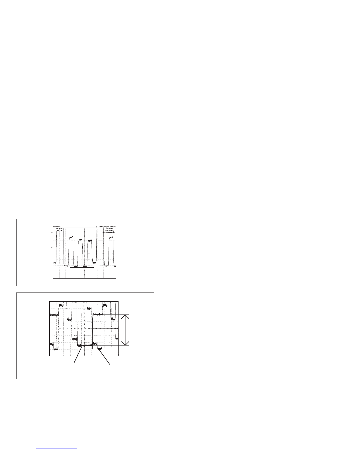
2-11: SEPARATION 1, 2
Please do the method (1) or method (2) adjustment.
Method (1)
1. Set the multi-sound signal generator for each different Lch and
R-ch frequency (Ex. L-ch=2KHz, R-ch=400Hz) and receive the
RF.
2. Connect the oscilloscope to the Audio Out Jack.
3. Activate the adjustment mode display of Fig. 1-1 and press the
channel button (34) on the remote control to select “SEP1”.
4. Press the VOL. UP/DOWN button on the remote control to adjust
it until the audio output wave becomes a fine sine wave.
5. Press the CH UP button once the set to “SEP 2” mode.
Then perform the above adjustment 4.
Method (2)
1. Set the multi-sound signal generator L-ch=1KHz, R-ch =Non
input and receive the RF.
2. Connect the oscilloscope to the Audio Out Jack (R-ch).
3. Press the AUDIO SELECT button on the remote control to set to
the stereo mode.
4. Activate the adjustment mode display of Fig. 1-1 and press the
channel button (34) on the remote control to select “SEP 1”.
5. Press the VOL. UP/DOWN button on the remote control to adjust
it until the R-ch output becomes minimum.
6. Set the multi-sound signal generator L-ch=Non input, R-ch=1KHz
and receive the RF.
7. Connect the oscilloscope to the Audio Out Jack (L-ch).
8. Activate the adjustment mode display of Fig. 1-1 and press the
channel button (35) on the remote control to select “SEP 2”.
9. Press the VOL. UP/DOWN button on the remote control to adjust
it until the L-ch output becomes minimum.
2-12: BRIGHT CENTER
1. Receive the monoscope pattern. (RF Input)
2. Using the remote control, set the brightness and contrast to
normal position.
3. Activate the adjustment mode display of Fig. 1-1 and press the
channel button (16) on the remote control to select “BRI. CENT”.
4. Press the VOL. UP/DOWN button on the remote control until the
white 15% is starting to be visible.
5. Receive the monoscope pattern. (Audio Video Input)
6. Press the TV/VCR button on the remote control to set to the AV
mode. Then perform the above adjustments 2~4.
7. Press the TV/VCR button on the remote control to set to the CS
mode.
8. Activate the adjustment mode display of Fig. 1-1 and press the
channel button (16) on the remote control to select “BRI. CENT”.
9. Press the VOL. UP/DOWN button on the remote control to set
the same step numbers as the AV.
Fig. 2-1
TV
00 OSD 35
A B

10
AV-14F704
No. 52130
2-13: TINT/COLOR CENT
1. Receive the color bar pattern. (RF Input)
2. Connect the oscilloscope to TP024.
3. Using the remote control, set the brightness, contrast, color and
tint to normal position.
4. Activate the adjustment mode display of Fig. 1-1 and press the
channel button (24) on the remote control to select “TINT”.
5. Press the VOL. UP/DOWN button on the remote control until the
section “A” becomes a straight line
(Refer to Fig. 2-2).
6. Connect the oscilloscope to TP023.
7. Press the CH DOWN button 2 times to set to “COL. CENT”
mode.
8. Adjust the VOLTS RANGE VARIABLE knob of the oscilloscope
until the range between white 100% and 0% is set to 4.4 scales
on the screen of the oscilloscope.
9. Press the VOL. UP/DOWN button on the remote control until the
red color level is adjusted to 115 ± 10% of the white level.
(Refer to Fig. 2-3)
10. Receive the color bar pattern. (Audio Video Input)
11. Press the TV/VCR button on the remote control to set to the AV
mode. Then perform the above adjustments 2~9.
12. Press the TV/VCR button on the remote control to set to the CS
mode.
13. Activate the adjustment mode display of Fig. 1-1 and press the
channel button (24) on the remote control to select “TINT”.
14 Press the VOL. UP/DOWN button on the remote control to set
the same step numbers as the AV.
15. Press the CH DOWN button 2 times to set to “COL.CENT”
mode.
16. Press the VOL. UP/DOWN button on the remote control to set
the same step numbers as the AV.
2-14: CONTRAST MAX MANUAL
1. Activate the adjustment mode display of Fig. 1-1 and press the
channel button (18) on the remote control to select “CONT.
MAX”.
2. Press the VOL. UP/DOWN button on the remote control until the
contrast step No. becomes “89”.
3. Receive a broadcast and check if the picture is normal.
4. Press the TV/VCR button on the remote control to set to the AV
mode. Then perform the above adjustments 1~3.
5. Press the TV/VCR button on the remote control to set to the CS
mode.
6. Activate the adjustment mode display of Fig. 1-1 and press the
channel button (18) on the remote control to select “CONT.
MAX”.
7. Press the VOL. UP/DOWN button on the remote control until the
contrast step No. becomes “72”.
2-15: Confirmation of Fixed Value (step No.)
Please check if the fixed values of the each adjustment items are
set correctly referring below.
NO. FUNCTION RF/AV/CS
02 H. VCO 03
04 AFC GAIN 06
05 V. SHIFT 00
06 H. SIZE 00
09 VS CORRECTION 42
15 BRIGHT MAX 150
17 BRIGHT MIN 75
19 CONTRAST CENT 50
20 CONTRAST MIN 18
21 COLOR MAX 90
23 COLOR MIN 00
25 SHARPNESS 35
26 Cb DELAY FINE 00
27 Cr DELAY FINE 00
28 Cb PEDESTAL ADJ 08
29 Cr PEDESTAL ADJ 08
30 E/W PARABOLA 31
31 E/W CORNER 31
32 E/W TRAPEZIUM 31
Fig. 2-2
“A”
Fig. 2-3
White 100% RED Level
100%

No. 52130 11
AV-14F704
3. PURITY AND CONVERGENCE
ADJUSTMENTS
NOTE
1. Turn the unit on and let it warm up for at least 30 minutes before
performing the following adjustments.
2. Place the CRT surface facing east or west to reduce the
terrestrial magnetism.
3. Turn ON the unit and demagnetize with a Degauss Coil.
3-1: STATIC CONVERGENCE (ROUGH ADJUSTMENT)
1. Tighten the screw for the magnet. Refer to the adjusted CRT for
the position. (Refer to Fig. 3-1)
If the deflection yoke and magnet are in one body, untighten the
screw for the body.
2. Receive the green raster pattern from the color bar generator.
3. Slide the deflection yoke until it touches the funnel side of the
CRT.
4. Adjust center of screen to green, with red and blue on the sides,
using the pair of purity magnets.
5. Switch the color bar generator from the green raster pattern to
the crosshatch pattern.
6. Combine red and blue of the 3 color crosshatch pattern on the
center of the screen by adjusting the pair of 4 pole magnets.
7. Combine red/blue (magenta) and green by adjusting the pair of 6
pole magnets.
8. Adjust the crosshatch pattern to change to white by repeating
steps 6 and 7.
3-2: PURITY
NOTE
Adjust after performing adjustments in section 3-1.
1. Receive the green raster pattern from color bar generator.
2. Adjust the pair of purity magnets to center the color on the
screen.
Adjust the pair of purity magnets so the color at the ends are
equally wide.
3. Move the deflection yoke backward (to neck side) slowly, and
stop it at the position when the whole screen is green.
4. Confirm red and blue color.
5. Adjust the slant of the deflection yoke while watching the screen,
then tighten the fixing screw.
3-3: STATIC CONVERGENCE
NOTE
Adjust after performing adjustments in section 3-2.
1. Receive the crosshatch pattern from the color bar generator.
2. Combine red and blue of the 3 color crosshatch pattern on the
center of the screen by adjusting the pair of 4 pole magnets.
3. Combine red/blue (magenta) and green by adjusting the pair of 6
pole magnets.
3-4: DYNAMIC CONVERGENCE
NOTE
Adjust after performing adjustments in section 3-3.
1. Adjust the differences around the screen by moving the deflec-
tion yoke upward/downward and right/left.
(Refer to Fig. 3-2-a)
2. Insert three wedges between the deflection yoke and CRT funnel
to fix the deflection yoke.
(Refer to Fig. 3-2-b)
DEFLECTION YOKE
DEFLECTION YOKE SCREW
MAGNET SCREW
6 POLE MAGNETS
4 POLE MAGNETS
PURITY MAGNETS
Fig. 3-2-b
Fig. 3-2-a
Fig. 3-1
R G B
R
G
BR
G
B
R G B
UPWARD/DOWNWARD SLANT RIGHT/LEFT SLANT
WEDGE WEDGE
WEDGE
WEDGE POSITION

12
AV-14F704
No. 52130
4. ELECTRICAL ADJUSTMENT PARTS LOCATION GUIDE (WIRING CONNECTION)
CP803 CP801B
CP802B
CD802
CP806
R803
R805
TP024
TP023
J801
W003
TP003
VR502
CP101
CP801A
FB401
J705 J706
J707
CP802A
TU001
VR401
CD801
CRT
CRT
CP401
AC IN
CP1001
SPEAKER
CRT PCB
MAIN PCB
CRT
L503
CP502
CD501

No. 52130 13
AV-14F704
GUIDE FOR REPAIRING
IC DESCRIPTION
MAIN PCB OEC7093A (IC101)
No. Pin name Symbol I/O Logic Function Option
1 P11/SCL1 AUDIO MUTE O 0 Audio MUTE Output. C-MOS
2 P00/PWM0 EXT MUTE O 1 Audio MUTE Output for external Output. Nch-OD
3 P01/PWM1 VOLUME O 1 Volume PWM output. Nch-OD
4 P02/PWM2 BBE-H O BBE Control Output. Nch-OD
5 P03/PWM3/AD1 AFT I Voltage of tuning input. Nch-OD
6 P04/PWM4/AD2 KEY1 I Main unit key input. Nch-OD
7 P05/AD3 KEY2 I Main unit key input. Nch-OD
8 P06/INT2/AD4 X-RAY I Input terminal of X-RAY detection. Nch-OD
9 P07/INT1 REMOCON I Remote control input. Nch-OD
10 P20/SCLK/AD5 ON TIME LED O ON-TIMER LED control output. C-MOS
11 P21/AOUT/AD6 S IN I S-connectio input. C-MOS
12 P22/SIN/AD7 Y/C SW O External in select output. C-MOS
13 P23/TIM3 AUDIO SW O Audio in select output. C-MOS
14 P24/TIM2 O C-MOS
15 P25/INT3 OPOWER FAIL I 0 Power failure detector input. C-MOS
16 P26/X CIN DEGAUSS_H O 1 Degauss output. C-MOS
17 P27/X COUT X-RAY_TEST O 1 X-RAY detector input. C-MOS
18 CNVSS CNVSS GND
19 XIN X in I Main Oscillation.
20 XOUT X out O Main Oscillation.
21 VSS VSS GND
22 VCC VCC 5V
23 FILT FILT
24 HLF HLF O Filter of slicer.
25 VHOLD V.HOLD I Condenser of slicer.
26 CVIN CVIN I Video signal input.
27 RESET RESET I 0 Reset signal input.
28 FSCIN (FSC IN) I (Main Clock Occurrence circuit input)
29 PON CONT/P15 POWER O 1 Power control output. C-MOS
30 P31/SCL3 SCL1 O Serial clock output. (IIC BUS) C-MOS
31 P30/SDA3 SDA1 I/O Serial data input/output. C-MOS
32 CLK CONT/P10 (CLOCK CONT) O (Main Clock Request output) C-MOS
33 P55/OUT BRANK O 1 BLANK Output for OSD/CCD. C-MOS
34 P54/R RED R O 1 Red output of RGB image output. C-MOS
35 P53/G GREEN G O 1 Green output of RGB image output. C-MOS
36 P52/B BLUE B O 1 Blue output of RGB image output. C-MOS
37 P51/VSYNC V.SYNC I 0 Vertical synchronization input.
38 P50/HSYNC H.SENC I 0 Horizontal synchronization input.
39 P16/AD8/TIM2 SYNC I Input terminal for H-SYNC. C-MOS
40 P14/SDA2 IIC_OFF I 0 Serial clock/data stop input. C-MOS
41 P13/SDA1 PROTECT O 1 Output HIGH at turning off a television. C-MOS
42 P12/SCL2 H_CTL O 1 Output HIGH at turning off a television. C-MOS

14
AV-14F704
No. 52130
TROUBLESHOOTING GUIDE
NO POWER
Yes
Is the voltage at the point (A)
in the Figure DC160V ?
Is the voltage at pin G
of Q502 DC5V ?
Yes
No
Check R501 and R541.
Check the rectifying circuit.
Yes
No
Yes
No
Is the voltage at the point (B)
in the Figure DC164V ?
Is the voltage at the point (C)
in the Figure AC120V ?
Yes
No
Broken wire of L501.
Is the voltage on both
ends of S501 AC120V ? Broken wire of F501.
Yes
No
Broken wire of AC cord or check
S501.
Is the voltage at the point (E)
in the Figure AC120V ?
Check Q502 and associated circuit.
Check Q514 and associated circuit.
No
T501
58
A
D
S
G
3
Q514
Q502
IC504
R501
B
D501~D504
L501
C
E
F501
CD501

No. 52130 15
AV-14F704
Is the heater voltage at
pin 4 of J801 AC6.4V ?
Is the high voltage of
ANODE 27KV~28KV ?
No
NO RASTER
Does the RASTER
appear at maximum
BRIGHT/CONTRAST ?
Yes
No
Is the voltage of pin 1 of
CP801 DC180V ?
Yes
No
Check the output circuit and
associated circuit.
Check the 180V line.
Yes Yes
No
Contact defects of CRT or CRT
Socket.
Check the HEATER circuit.
Yes
No
Is collector voltages
of Q405 DC115V and
Q402 DC27V ?
Check FB401 and associated circuit.
No
Yes
Is the waveform at base
of Q402 normal ?
No
Yes
Is the waveform at pin
8 of IC601 normal ?
Check the circuit from pin 8 of
IC601 to Q402.
Check IC601 and associated circuit.
Check Q402 and check peripheral
circuit.

16
AV-14F704
No. 52130
NO COLOR
Are the waveforms at pins 3,
7 and 9 of J801 normal ?
Yes
No
Defect of CRT or contact defects
of J801.
Are the waveforms at pins 3,
4 and 5 of CP802 normal ?
Yes
No
Check the output circuit and
associated circuit.
Are the waveforms at
pins 14, 15 and 16 of
IC602 normal ?
Yes
No
Check R, G, B signal output
from IC601 to CP802.
Is the pulse of crystal
X602 normal ?
No
Yes
CHANG X602.
Check the associated circuit of IC601.

No. 52130 17
AV-14F704
NO VERTICAL
Is the waveform at pin
6 of CP401 normal ?
Yes
No
Check DY.
Is the waveform at pin
1 of IC401 normal ?
No
Yes Is the voltage at pin 2
of IC401 25V?
Yes
No
Check IC401 and check the
peripheral circuit.
Check the 25V line.
Is the waveform at pin
63 of IC601 normal ?
No
Yes
Check the associated circuit of IC601.
Check the circuit from pin 63 of
IC601 to pin 1 of IC401.

18
AV-14F704
No. 52130
NO SOUND
Yes
Is sound setting appropriate ?
Is the waveform at pins 7
and 12 of IC1001?
Yes
No
Check speaker.
Check IC902 and check
AUDIO signal in put.
Is the AUDIO signal input
at pins 3 and 30 of IC302?
Yes
No
Check IC302 and peripheral circuit.
Is the AUDIO signal at pins
16 and 19 of IC303?
Yes Check IC1001 and
check peripheral circuit.
No
NO CCD
Is the video signal at pin
26 of IC101 ?
Is the video signal at
pin 17 of TU001 ?
No
Yes Check TU001 and check
peripheral circuit.
Check IC601 and check
paripheral circuit.
Yes Check IC101 and check
peripheral circuit.
No

Printed in Japan
200305WPC
(No. 52130)
JVC SERVICE & ENGINEERING COMPANY OF AMERICA
DIVISION OF JVC AMERICAS CORP.
www.jvcservice.com(US Only)
JVC CANADA INC.
Head office :21 Finchdene Square Scarborough, Ontario M1X 1A7 (416)293-1311
Other manuals for AV 14F704
1
Table of contents
Other JVC TV manuals

JVC
JVC AV-21F1P User manual

JVC
JVC AV-21MX76 User manual

JVC
JVC AV-21L41/BK User manual

JVC
JVC AV-21KM3SN User manual

JVC
JVC AV-16N8 Use and maintenance manual

JVC
JVC LT-52GZ79 User manual

JVC
JVC AV-21C116 User manual

JVC
JVC AV-28MS1SN User manual

JVC
JVC AV-29L6SU, AV-29L6BU User manual

JVC
JVC AV-29R8TEE User manual