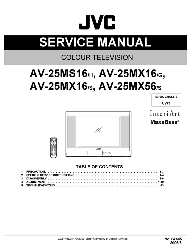
JVC pd-42dxt User manual

SERVICE MANUAL
COPYRIGHT © 2003 VICTOR COMPANY OF JAPAN, LTD. No.52108
2003/01
PD-42DXT
PDP COLOR TELEVISION
52108200301
PD-42DXT
TABLE OF CONTENTS
1 PRECAUTIONS . . . . . . . . . . . . . . . . . . . . . . . . . . . . . . . . . . . . . . . . . . . . . . . . . . . . . . . . . . . . . . . . . . . . . . . 1-3
2 SPECIFIC SERVICE INSTRUCTIONS . . . . . . . . . . . . . . . . . . . . . . . . . . . . . . . . . . . . . . . . . . . . . . . . . . . . . . 1-6
3 ADJUSTMENTS . . . . . . . . . . . . . . . . . . . . . . . . . . . . . . . . . . . . . . . . . . . . . . . . . . . . . . . . . . . . . . . . . . . . . . 1-20
4 TROUBLE SHOOTING. . . . . . . . . . . . . . . . . . . . . . . . . . . . . . . . . . . . . . . . . . . . . . . . . . . . . . . . . . . . . . . . . 1-52
TS-42DXT
[FRONT SPEAKER (R)]
TS-42DXT
[FRONT SPEAKER (L)]
TS-42DXT
[SUB WOOFER]
[RM-C289]
PD-42DXT
[PLASMA DISPLAY UNIT]
TU-42DXT
[RECEIVER UNIT]
BASIC CHASSIS
SB3

PD-42DXT
1-2 (No.52108)
SPECIFICATION
Item Contents
Dimensions (W x H x D) Plasma display unit 103.5cm x 64.0cm x 9.8cm (without Front speaker)
112.3cm x 64.0cm x 10cm (with Front speaker)
Receiver unit 43.5cm x 9.9cm x 38.2cm
Front speaker 4.2cm x 63.9cm x 5.4cm
Sub woofer 3.5cm x 23.0cm x 12.6cm
Mass Plasma display unit 33.0kg (without Front speaker)
35.5kg (with Front speaker)
Receiver unit 5.6kg
Front speaker 0.8kg (per one speaker without attachment metal)
Sub woofer 3.7kg
Color System NTSC-M
Receiving frequency VHF 91.25MHz~103.25MHz (1~3ch)
171.25MHz~217.25MHz (4~12ch)
UHF 471.25MHz~765.25MH (13~62ch)
CATV 109.25MHz~165.25MHz (C13~C22ch)
223.25MHz~313.25MHz (C23~C38ch)
Intermediate frequency Video: 58.75MHz
Sound: 54.25MHz
Color: 55.17MHz (3.58MHz)
Power Input AC110V, 50Hz/60Hz
Power Consumption Plasma display unit Operate: 360W, Stand by: 0.4W
Receiver unit Operate: 41W, Stand by: 0.8W
Plasma display panel (PDP) 42-inch wide aspect (16:9) QLE0020-001
Screen size (W x H x D) 92.1cm x 51.8cm x 105.7cm
Display pixels Horizontal: 1024 dots
Vertical: 768 dots
Audio output Front: 10W+10W, Sub woofer: 15W
Speaker Front speaker 9.5cm x 1cm square x 2
Sub woofer (for bass sound) 16cm Round x 1
Aerial input VHF/UHF 75 ohm Unbalanced Coaxial
Input /
Output jack
VIDEO/AUDIO IN
VIDEO 1
VIDEO 2
VIDEO 3 (DVD)
VIDEO 4
S1-VIDEO
(VIDEO 4: S-VIDEO)
Mini DIN4 pin x 3
Y: 1V (p-p) Positive (Negative sync provided), 75 ohm
C: 0.286V (p-p) (Burst signal), 75 ohm
VIDEO 1V (p-p) Positive (Negative sync provided), 75 ohm RCA pin jack x 4
AUDIO 500mV (rms), High Impedance RCA pin jack x 8
VIDEO 3/DVD
COMPONENT
VIDEO IN
1125i / 750p
525p / 525i
RCA pin jack x 3
Y: 1V (p-p) (Sync signal: ±0.35V(p-p), 3-value sync.), 75 ohm
Pb/Pr: ±0.35V(p-p), 75 ohm
Y: 1V (p-p) Positive (Negative sync provided), 75 ohm
Cb/Cr: 0.7V(p-p), 75 ohm
D4 VIDEO IN
(VIDEO 1: D-VHS,
VIDEO 4)
1125i / 750p
525p / 525i
2 sequences 14pin x 1
Y: 1V (p-p) (Sync signal: ±0.35V(p-p), 3-value sync.), 75 ohm
Pb/Pr: ±0.35V(p-p), 75 ohm
Y: 1V (p-p) Positive (Negative sync provided), 75 ohm
Cb/Cr: 0.7V(p-p), 75 ohm
MONITOR /
REC OUT S1-VIDEO
Mini DIN4 pin x 1
Y: 1V (p-p) Positive (Negative sync provided), 75 ohm
C: 0.286V (p-p) (Burst signal), 75 ohm
VIDEO 1V (p-p), 75 ohm, Negative sync RCA pin jack x 2
AUDIO 500mV (rms), Low Impedance RCA pin jack x 2
AUDIO OUT (Fixed) 500mV (rms), Low Impedance RCA pin jack x 2
Headphone 3.5mm Stereo mini jack x 1
AV COMPULINK III 3.5mm mini jack x 1
i-LINK IN/OUT 4 Pin S400 x 2
Optical digital audio output -18dBm, 660nm (MPEG 2 AAC or PCM according to the menu settings)
Telephone line 2P Modular jack, Modem transmission rate 2400bps
Video remote controller 3.5mm mini jack
Pin No. Signal name Pin No. Signal name Pin No. Signal name Pin No. Signal name
1 Y 5 Pr/Cr 9 LINE-2 13 Spare line 3
2 Y GND 6 Pr/Cr GND 10 Spare line 2 14 Switch
3 Pb/Cb 7 Spare line 1 11 LINE-3
4 Pb/Cb GND 8 LINE-1 12 Switch GND
D TERMINAL (Pin layout)
8
1234567
91011121314

PD-42DXT
(No.52108)1-3
SECTION 1
PRECAUTIONS
1.1 SAFETY PRECAUTIONS
(1) The design of this product contains special hardware,
many circuits and components specially for safety
purposes. For continued protection, no changes should be
made to the original design unless authorized in writing by
the manufacturer. Replacement parts must be identical to
those used in the original circuits. Service should be
performed by qualified personnel only.
(2) Alterations of the design or circuitry of the products should
not be made. Any design alterations or additions will void
the manufacturer's warranty and will further relieve the
manufacturer of responsibility for personal injury or
property damage resulting therefrom.
(3) Many electrical and mechanical parts in the products have
special safety-related characteristics. These
characteristics are often not evident from visual inspection
nor can the protection afforded by them necessarily be
obtained by using replacement components rated for
higher voltage, wattage, etc. Replacement parts which
have these special safety characteristics are identified in
the parts list of Service manual. Electrical components
having such features are identified by shading on the
schematics and by ( ) on the parts list in Service
manual. The use of a substitute replacement which does
not have the same safety characteristics as the
recommended replacement part shown in the parts list of
Service manual may cause shock, fire, or other hazards.
(4) Don't short between the LIVE side ground and ISOLAT-
ED (NEUTRAL) side ground or EARTH side ground
when repairing.
Some model's power circuit is partly different in the GND.
The difference of the GND is shown by the LIVE : ( ) side
GND, the ISOLATED (NEUTRAL) : ( ) side GND and
EARTH : ( ) side GND.
Don't short between the LIVE side GND and ISOLATED
(NEUTRAL) side GND or EARTH side GND and never
measure the LIVE side GND and ISOLATED (NEUTRAL)
side GND or EARTH side GND at the same time with a
measuring apparatus (oscilloscope etc.).
If above note will not be kept, a fuse or any parts will be
broken.
(5) If any repair has been made to the chassis, it is
recommended that the B1 setting should be checked or
adjusted (See ADJUSTMENT OF B1 POWER SUPPLY).
(6) The high voltage applied to the picture tube must conform
with that specified in Service manual. Excessive high
voltage can cause an increase in X-Ray emission, arcing
and possible component damage, therefore operation
under excessive high voltage conditions should be kept to
a minimum, or should be prevented. If severe arcing
occurs, remove the AC power immediately and determine
the cause by visual inspection (incorrect installation,
cracked or melted high voltage harness, poor soldering,
etc.). To maintain the proper minimum level of soft X-Ray
emission, components in the high voltage circuitry
including the picture tube must be the exact replacements
or alternatives approved by the manufacturer of the
complete product.
(7) Do not check high voltage by drawing an arc. Use a high
voltage meter or a high voltage probe with a VTVM.
Discharge the picture tube before attempting meter
connection, by connecting a clip lead to the ground frame
and connecting the other end of the lead through a 10k
2W resistor to the anode button.
(8) When service is required, observe the original lead dress.
Extra precaution should be given to assure correct lead
dress in the high voltage circuit area. Where a short circuit
has occurred, those components that indicate evidence of
overheating should be replaced.
Always use the manufacturer's replacement components.
(9) Isolation Check
(Safety for Electrical Shock Hazard)
After re-assembling the product, always perform an
isolation check on the exposed metal parts of the cabinet
(antenna terminals, video/ audio input and output
terminals, Control knobs, metal cabinet, screw heads,
earphone jack, control shafts, etc.) to be sure the product
is safe to operate without danger of electrical shock.
a) Dielectric Strength Test
The isolation between the AC primary circuit and all metal
parts exposed to the user, particularly any exposed metal
part having a return path to the chassis should withstand a
voltage of 3000V AC (r.m.s.) for a period of one second. (.
. . . Withstand a voltage of 1100V AC (r.m.s.) to an
appliance rated up to 120V, and 3000V AC (r.m.s.) to an
appliance rated 200V or more, for a period of one second.)
This method of test requires a test equipment not generally
found in the service trade.
b) Leakage Current Check
Plug the AC line cord directly into the AC outlet (do not use
a line isolation transformer during this check.). Using a
"Leakage Current Tester", measure the leakage current
from each exposed metal part of the cabinet, particularly
any exposed metal part having a return path to the chassis,
to a known good earth ground (water pipe, etc.). Any
leakage current must not exceed 0.5mA AC (r.m.s.).
However, in tropical area, this must not exceed 0.2mA AC
(r.m.s.).
Alternate Check Method
Plug the AC line cord directly into the AC outlet (do not
use a line isolation transformer during this check.). Use
an AC voltmeter having 1000 ohms per volt or more
sensitivity in the following manner. Connect a 1500 ohm
10W resistor paralleled by a 0.15µF AC-type capacitor
between an exposed metal part and a known good earth
ground (water pipe, etc.). Measure the AC voltage
across the resistor with the AC voltmeter. Move the
resistor connection to each exposed metal part,
particularly any exposed metal part having a return path
to the chassis, and measure the AC voltage across the
resistor. Now, reverse the plug in the AC outlet and
repeat each measurement. Any voltage measured must
not exceed 0.75V AC (r.m.s.). This corresponds to
0.5mA AC (r.m.s.).
However, in tropical area, this must not exceed 0.3V AC
(r.m.s.). This corresponds to 0.2mA AC (r.m.s.).
AC VOLTMETER
(HAVING 1000 /V,
OR MORE SENSITIVITY)
PLACE THIS PROBE
ON EACH EXPOSED
METAL PART
1500 10W
0.15 F AC-TYPE
GOOD EARTH GROUND

PD-42DXT
1-4 (No.52108)
1.2 INSTALLATION
1.2.1 HEAT DISSIPATION
If the heat dissipation vent behind this unit is blocked, cooling
efficiency may deteriorate and temperature inside the unit will
rise. The temperature sensor that protects the unit will be
activated when internal temperature exceeds the pre-determined
level and power will be turned off automatically.
Therefore, please make sure pay attention not to block the heat
dissipation vent as well as the ventilation outlet behind the unit
and ensure that there is room for ventilation around it.
1.2.2 INSTALLATION REQUIREMENTS
Ensure that the minimal distance is maintained, as specified
below, between the unit with and the surrounding walls, as well
as the floor etc.
Install the unit on stable flooring or stands.
Take precautionary measures to prevent the unit from tipping in
order to protect against accidents and earthquakes.
1.2.3 FALL TIP PREVENTION MEASURES
Take precautionary measures to prevent the unit from falling or
tipping to protect against emergencies such as earthquakes as
well as accidents.
Fasten the supplied hook for tip fall prevention using the screws,
also supplied, behind the display unit, and use them together
with durable cords (to be purchased separately) to secure the
unit to a robust part such as the wall surface or pillars.
150mm or more 200mm or more 150mm
or more
200mm
or more
50mm or more
SPACE REQUIRED FOR INSTALLATION OF THE DISPLAY UNIT
5ᤋ ᤋ Ꮐ㖸ჿฝ
ఝవ
ࡋ࠶࠼ࡎࡦ
ࡆ࠺ࠝജ
㔚Ḯ
5ᤋ ᤋ Ꮐ㖸ჿฝ
ఝవ
ࡋ࠶࠼ࡎࡦ
ࡆ࠺ࠝജ
㔚Ḯ
)'/56 # 4
100mm or more100mm or more
100mm or more
100mm or more 100mm or more
SPACE REQUIRED FOR INSTALLATION OF THE RECEIVER UNIT
The supplied hook for tipfall prevention

PD-42DXT
(No.52108)1-5
1.3 PRECAUTIONS DURING NOTES FOR TRANSPORTATION
When transporting the display unit, pressure exerted on the
internal PDP (Plasma Display Panel) due to improper handling
(such as tossing and dropping) may cause damages even when
the unit is carefully packed. To prevent accidents from occurring
during transportation, pay careful attention prior to delivery such
as through explaining the handling instructions to transporters.
Ensure that the following requirements are met during
transportation, as the PDP of this unit is made of glass and
therefore fragile:
(1) Avoid vibrations and impacts
The unit may be broken if it is toppled sideways even when
properly packed. Ensure that the unit is carried by at least
2 persons and pay careful attention not to exert any
vibration or impact on it.
(2) Do not place equipment horizontally
Ensure that it is placed upright and not horizontally during
transportation and storage as the PDP is very vulnerable to
lateral impacts and may break easily under such
circumstances.
During transportation, ensure that the unit is loaded along
the traveling direction of travel of the vehicle, and avoid
stacking them on one another.
For storage, ensure that they are stacked in 2 layers or less
even when placed upright.
1.4 RESIDUAL IMAGE / BURN-IN ON SCREEN
Like CRTs, ‘burn-ins’ may occur when a same image is
continuously displayed over an extended period of time.
As Tthis may also shorten the life span of the PDP. Therefore,
turn off the display when not in use, scroll the screen, make use
of screen-savers, or allow even distribution on the display by
inverting the brightness, switching to complementary colors or
inserting animated images at periodic intervals.
As burn-in is more likely to occur with high brightness and
contrast settings, try to use neutral gradations or medium tone
colors.
Burn-in does not occur in the case of animated images.
When switching to another image after continuous display of the
previous image, residual images may become prominent, as
luminance in a part of the display is higher than the other parts.
This is not a defect but is because due to the discharge surface
of the lighted portion has becomebeing relatively activated and
its luminance higher than the unlighted parts.
1.5 INFRARED RAYS
Near Near-infrared rays (800nm to 1000nm) are emitted from the
front of the panel, and this may give rise to glitchescause
malfunctions in infrared remote controls or communication
systems placed near it. In this case, avoid direct infrared rays
(and reflected rays in some cases) from the screen by either
changing the direction of the unit or other infrared systems or
securing a longer keeping a distance from the screen.
1.6 OPTICAL FILTER (PANEL FILTER)
Avoid placing the unit under direct sunlight over a prolonged
period of time. This may cause the optical filter to deteriorate in
quality and color.
Clean the filter surface by wiping it softly lightly with outing
flannels a soft and lightly fuzz cloth (such as flannel).
Do not use solvents such as benzine or thinner to wipe the filter
surface. This may cause the filter to deteriorate in quality or the
coating on the surface to come off.
As Tthe filter surface is fragile., Ddo not scratch or hit it with hard
materials.
1.7 NOTES PRECAUTIONS FOR REPLACEMENT OF EXTE-
RIOR PARTS
Take note of the following when replacing exterior parts (back
REAR COVER, FRONT PANEL, optical filter):
Do not exert pressure on the front of the PDP (glass surface).
Pay careful attention not to scratch or stain the front of the PDP
(surface) with hands.
When replacing exterior parts, the front of the PDP should be
placed facing downward. Place a mat, etc. underneath to avoid
causing scratches to the front surface.
However, never use materials that are too soft (such as blanket
cloth). If replacement is made with the PDP surface facing
downward and in contact with the blanket, pressure may be
exerted on the PDP, thus causing damages to it.

PD-42DXT
1-6 (No.52108)
SECTION 2
SPECIFIC SERVICE INSTRUCTIONS
2.1 FEATURES
2.1.1 HIGH-DEFINITION IMAGE TECHNOLOGY (DET), HIGH QUALITY SOUND TECHNOLOGY (DD) EQUIPPED
2.1.2 MAIN FUNCTION
2.1.3 ASPECT CONTROL
2.1.4 MULTI-SCREEN FUNCTION
DET (Digital Emotional Tech-
nology)
Picture processing technology that changes various kinds of image signal, ranging from ground-
based broadcast to D4 format of the digital satellite broadcast, to XGA high vision picture quality,
thereby accomplishing detailed high density images.
DD (Direct Drive) "Acoustic device that is accomplished through the interfacing of computer simulation and the acous-
tic technology that we have developed over the years.
Attain wide and spontaneous acoustic field, real normal sound images that allows enjoyment of the
realistic sensation of reserved seats, from any audience seats."
SD Memory Card Picture data and sound data recorded in the SD memory card can be play backed. In addition, view-
ers can enjoy still picture from digital camera and music edited by computer.
Auto power off function when
no signal is present / Preven-
tion against forgetting to turn off
the TV.
The power supply of the TV will be cut off automatically when there is a continuous absence of signal
for 4 minutes, or when there is a maximum of 3 consecutive hours of no operation from user.
Off Timer Setting for situations such as falling asleep while watching TV, and for prevention against forgetting
to turn off the TV. The power supply of the TV will be cut off automatically when the time exceeds
the set up timing (maximum 2 hours).
Digital E.E Sensor The brightness of the screen adjusts automatically in accordance with the brightness of the room. It
is a function that is power saving and gentle to eyes.
Memo screen function "The images that are currently seen can be viewed on the memo screen (still picture).
It is convenient for taking down notes like application address and recipe of cooking program etc,
while enjoying the current program."
i. LINK Input/Output Terminal By just connecting an i. Link cable to the sharing device equipped with the i. Link terminal, interaction
of digital signal (referring to the image, sound & data broadcasting via satellite digital broadcast for
this unit) is possible. The interaction will not be affected even when the other devices are being dis-
rupted.
D4 Input Terminal D-VHS and DVD supporting terminal.
Natural cinema function When viewing film-originated movie and animation, misty outline can be seen in fast moving images.
Using natural cinema will enable viewing of clear images even in fast moving images.
Program navigation function [Program navigation] screen is for the purpose of operating the functions of the electronic program
guide. The program screen of the ground-based broadcast and digital satellite broadcast can be dis-
played when watching ground-based broadcast and digital satellite broadcast.
GR (Ghost reduction) Reduces ghost noise included in the ground-based broadcast.
Screen size switching Desired screen size (Auto panorama / Panorama / Closed caption panorama / Cinema / Full / Nor-
mal) can be selected.
Moving the screen up & down. Adjusts the vertical position of the screen.
Auto full mode Detects S1 signal and automatically goes to full mode.
Dual-screen 2 programs an be viewed at the same time.
Program List (12 screens) All the programs that are being received are displayed at the same time. Desired program can be
selected from the 12 screens being displayed.
Different channel program
(4 screens)
In addition to a current received program, three other programs are displayed at the same time.

PD-42DXT
(No.52108)1-7
2.2 TECHNICAL INFORMATION
2.2.1 PDP STRUCTURE AND CHARACTERISTIC
This unit (Display Unit) uses the flat type panel PDP (Plasma Display Panel), instead of the conventional CRT (Cathode Ray Tube),
as a display unit.
2.2.2 PIXEL (CELL) ARRAY
PDP is constructed by sealing the xenon, which emits neon and ultraviolet rays for discharging purpose, in between the electrodes
lay on the front glass substrate and rear glass substrate.
One pixel is composed of 3 RGB cells, with cell pitch of 0.299mm (1 pixel 0.897mm) horizontally and 0.675mm vertically.
The cell is arrayed in each RGB color as shown in Fig. 1. One pixel is formed by interlacing each RGB color cell.
One cell size is 0.299mm horizontally and 0.675mm vertically.
Fig.1 Alignment of pixel (cell)
2.2.3 PIXEL DEFECTS
Though PDP is made by means of ultra precise technology, there are cases whereby not all pixels (cell) will function properly. Pixel
defects, pixels that are always not lit, and on the contrary pixels that are always lit, exist depending on each case.
There are 2 types of Pixel defects, [Bright Dot Defects] and [Dark Dot Defects], as defined respectively in the following:
(1)Bright Dot Defects
Bright dot defects are pixel defects where the pixel should basically be unlit, but lit or blinks.
The presence of bright dot defects can be confirmed by inputting a full black signal (pattern).
(2)Dark Dot Defects
Black dot defects are pixel defects where the pixel should basically be lit, but does not lit, or is twice as bright when lit.
The presence of black dot defects can be confirmed by inputting a 100% full white signal (pattern).
R G B R G B
RGBRGB
GBRG B
GBRGB
R
R
RGBRG B
RGBRGB
GBRG B
GBRGB
R
R
No.1
Pixel
sequence
No.2
Pixel
sequence
No.1023
Pixel
sequence
No.1024
Pixel
sequence
No.1
Pixel line
No.2
Pixel line
Horizontally
Vertically
Direction
0.897mm(Horizontally)
Pixel pitch
0.299mm(Vertically)
Cell pitch
0.675mm
(Verticall)
Pixel pitch
(Cell pitch
1 pixel
(1 dot)
No.767
Pixel line
No.768
Pixel line
R
Cell
G
Cell
B
Cell

PD-42DXT
1-8 (No.52108)
2.3 MAIN MI-COM FUNCTIONAL TABLE [RECEIVER UNIT]
Pin No. Terminal name Port name I/O Function
1 BS-RxD SBO0 O PDP communication port
2 /MICON_V /VSYNC I Vertical synchronizing signal input (For OSD)
3 LB_PRO P84 I Low B protection detect (In detection: H)
4 NC NC - Not used
5 /RST /RST I Reset jack (In resetting: L)
6 CONV.BUSY P52 IRQ4 I Not used
7 /TEST /TEST I 3.3V
8OSD_YS YS OY
Ssignal output (For OSD)
9 /DPCRST P83 O Not used
10 BS/D P50 O In digital BS: L Other: H
11 A_MU P82 O Sound mute (TV) (In muting: H)
12 /MICON_H /HSYNC I Horizontal synchronizing signal input (For OSD)
13 M_MU P81 O Monitor output mute (In muting: H)
14 P46.OSDXI P46 OSDXI - Not used
15 P45.OSDXO P45 OSDXO - Not used
16 SDA2 P44 I/O Not used
17 AC_IN TM5IOB I AC power supply input
18 SCL2 P42 O Not used
19 TU_POW P41 O Tuner power control
20 VCOI VCOI I LPF input
21 PDO PDO O LPF output
22 /IP_RESET P80 O Reset (L)
23 OSD_YM DAYMOUT O YMsignal output (For OSD)
24 OSD_B DABOUT O B signal output (For OSD)
25 POW_LED P77 O Power supply LED (In lighting: H)
26 OSD_G DAGOUT O G signal output (For OSD)
27 OSD_R DAROUT O R signal output (For OSD)
28 VREF VREF I Not used
29 IP_ERR P76 I AMDP program load
30 IREF IREF I Not used
31 COMP COMP I Not used
32 AVDD AVDD I 3.3V
33 CLL CLL O Not used
34 VREFLS VREFLS I Standard voltage input (For SUB CCD)
35 SUB_CCD CVBS1 I Not used
36 NC NC - Not used
37 VSS VSS I GND
38 MAIN_CCD CVBS0 I Not used
39 VREFHS VREFHS I Standard voltage input (For CCD)
40 CLH CLH I Not used
41 VDD/VPP VDD(VPP) I 3.3V
42 CLKSW1 P75 O IP clock switch
43 CLKSW2 P74 O IP clock switch
44 ON_TIM P27 O Not used
45 PDP-Rx SBO1 O PDP communication

PD-42DXT
(No.52108)1-9
46 PDP-Tx P25 SBD1 I PDP communication
47 SBT1 SBT1 I Port for writing on board
48 AP_DATA P23 I Auto panorama data input
49 BS-RESET P22 O Not used
50 SRQ P21 O Not used
51 BS1.5CTL P20 O Not used
52 /DVI_RST PWM2 O Not used
53 DVI_HP PWM1 O Connection detect (digital signal)
54 /MDR_CON PWM0 O Image control (PWM output)
55 /BS_POW P73 O Not used
56 BS_CLK_SEL P14 O Not used
57 TU2_AID ADIN8 I Not used
58 /LOB_POW P72 O LOB power control
59 /COMPULINK /IRQ3 I Not used
60 /POWERGOOD /IRQ2 I Power condition check
61 MECHA_SW P10•/IRQ1 I Discontinuation of mechanical swtich detection
62 /MAIN_POW P71 O Main power control
63 NC NC - Not used
64 /B1_POW P70 O Not used
65 C/N ADIN4 I Not used
66 XÅ|RAY ADIN3 I Not used
67 EE_CDS ADIN2 I EE sensor input
68 KEY2 ADIN1 I Key scan data input (KEY2)
69 KEY1 ADIN0 I Key scan data input (KEY1)
70 SCL1 SCL1 O I2C bus clock (For EEPROM)
71 SDA1 SDA1 I/O I2C bus data (For EEPROM)
72 REMO RMIN•/IRQ0 I Remote control data input
73 AP_REQ P87 O Auto panorama request
74 VSS VSS I GND
75 OSC2 OSC2 O 4MHz oscillation
76 OSC1 OSC1 I 4MHz oscillation
77 VDD VDD I 3.3V
78 SCL0 SCL0 O I2C bus clock (For wide use)
79 AP_CLK P86 O Auto panorama clock
80 SDA0 SDA0 I/O I2C bus data (For wide use)
81 DVI_SDA P57SBT0 O I2C bus data (digital signal)
82 BS_TXD(D_DATA) P56SBD0 I Not used
83 NC NC - Not used
84 P_MU P85 O Image mute control
Pin No. Terminal name Port name I/O Function

PD-42DXT
1-10 (No.52108)
2.4 DISASSEMBLY PROCEDURE [DISPLAY UNIT]
Caution:
• When exchanging parts etc. with the front side (PDP side)
facing down, please place a protection sheet below before
starting, so as to prevent scratches on the front side.
2.4.1 REMOVING THE REAR COVER (Fig.1)
(1) Remove the power cord / system cable / speaker cord.
(2) Remove the 19 screws [A] and the 6 screws [B].
Fig.1
2.4.2 REMOVING THE TERMINAL COVER (Fig.2)
• Remove the REAR COVER.
(1) Remove the 2 screws [C], and withdraw the TERMINAL
COVER.
(2) Remove the 6 screws [D], and remove the SPEAKER
TERMINAL PWB.
NOTE:
• Disconnect the connector [CN60SP] from the
SPEAKER TERMINAL PWB.
Fig.2
2.4.3 REMOVING THE LINE FILTER PWB (Fig.3)
• Remove the REAR COVER.
• Remove the TERMINAL COVER.
(1) Remove the 6 screws [E], and remove the LINE FILTER
PWB together with the filter shield.
NOTE:
• Disconnect the connector [CN0PW] from the LINE
FILTER PWB.
• Disconnect the connector [CN900P] from the
SYSTEM POWER PWB.
• It is advisable to take note of the connecting location
(connector number) of the removed connectors.
2.4.4 REMOVING THE AUDIO PWB (Fig.3)
• Remove the REAR COVER.
• Remove the TERMINAL COVER.
(1) Remove the 4 screws [F], and remove the AUDIO PWB.
NOTE:
• Disconnect the connectors [CN60SP], [CN600K],
[CN60CA], [CN60CE], [CN60CF] from the AUDIO
PWB.
• It is advisable to take note of the connecting location
(connector number) of the removed connectors.
2.4.5 REMOVING THE SYSTEM POWER PWB (Fig.3)
• Remove the REAR COVER.
• Remove the TERMINAL COVER.
(1) Remove the 4 screws [G], and remove the SYSTEM
POWER PWB.
NOTE:
• Disconnect the connectors [CN900J], [CN90CB],
[CN90CA], [CN900K] from the SYSTEM POWER
PWB.
• It is advisable to take note of the connecting location
(connector number) of the removed connectors.
2.4.6 REMOVING THE DISPLAY INTERFACE PWB (Fig.3)
• Remove the REAR COVER.
• Remove the TERMINAL COVER.
(1) Remove the 4 screws [H], and remove the DISPLAY
INTERFACE PWB.
NOTE:
• Disconnect the connectors [CN0AH], [CN0CB],
[CN0CD], [CN0CC], [CN0AV], [CN0CF], [CN0CE]
from the DISPLAY INTERFACE PWB.
• It is advisable to take note of the connecting location
(connector number) of the removed connectors.
2.4.7 REMOVING THE PDP POWER PWB (Fig.3)
• Remove the REAR COVER.
• Remove the TERMINAL COVER.
(1) Remove the 6 screws [ I ], and remove the PDP POWER
PWB.
NOTE:
• Disconnect the connectors [CN00J], [CN0AU],
[CN0AT], [CN0AV] from the PDP POWER PWB.
• It is advisable to take note of the connecting location
(connector number) of the removed connectors.
(x19)
A
A
(x3)
B
(x3)
B
REAR COVER
TOP
TERMINAL COVER
SPEAKER
TERMINAL
PWB
C
D
(x2)
(x6)

PD-42DXT
(No.52108)1-11
Fig.3
2.4.8 REMOVING THE CHASSIS BASE (Fig.4)
• Remove the REAR COVER.
• Remove the TERMINAL COVER.
• Remove the FILTER SHIELD and LINE FILTER PWB.
• Remove the AUDIO PWB.
• Remove the SYSTEM POWER PWB.
• Remove the DISPLAY INTERFACE PWB.
• Remove the PDP POWER PWB.
(1) Remove the 2 screws [J] and 1 screw [K].
(2) Lift upwards and withdraw the AC inlet in a front direction.
(3) Remove the 4 screws [L], and remove the CHASSIS
BASE.
Fig.4
2.4.9 REMOVING THE PDP UNIT (Fig.5)
• Remove the REAR COVER.
• Remove the TERMINAL COVER.
• Remove the CHASSIS BASE (with each PWB affixed on the
CHASSIS BASE).
(1) Remove the 4 screws [M], and remove the terminal brack-
et.
(2) Disconnect the connectors of the following PWB.
NOTE:
• Disconnect the connector [CN0PW] from the LINE
FILTER PWB.
• Disconnect the connectors [CN0AU] and [CN0AT]
from the PDP POWER PWB.
• Disconnect the connector [CN0AH] and earth wire
from the DISPLAY INTERFACE PWB.
• It is advisable to take note of the connecting location
(connector number) of the removed connectors.
(3) Remove the 4 screws [N] and 5 screws [O], and remove
the 2 pieces of SUPPORT BRACKET (BOTTOM).
(4) Remove the 4 screws [P] and remove the 2 pieces of BACK
FRAME (BOTTOM).
(5) Remove the 4 screws [Q] and 1 screw [R], and remove the
2 pieces of SUPPORT BRACKET (UPPER).
(6) Remove the 2 screws [S] and 1 screw [T], and remove the
panel shield.
(7) Remove the 4 screws [U].
(8) Life the PDP upright and remove it with enough care not to
impose shock to the PDP.
Caution:
• Two or more people are required to remove the PDP
unit
• The gas pouring port is covered with the protection
material.In operation, be careful not to damage the gas
pouring port.
• Do not touch the front side (glass) of the PDP with your
fingers.
INSULATOR SHEET
H
(x4)
I
(x6)
E
F
(x6)
(x4)
SYSTEM
POWER
PWB
LINE FILTER
PWB
AUDIO PWB
PDP POWER PWB
DISPLAY INTERFACE PWB
FILTER SHIELD
G
(x4)
K(x2)
J
(x4)
L
AC INLET
COVER
CHASSIS BASE

PD-42DXT
1-12 (No.52108)
Fig.5
(x4)
N
(x2)
N
M
(x3)
O
(x2)
P
(x2)
S
T
(x2)
Q
(x2)
Q
R
(x4)
U
(x2)
N
(x2)
O
(x2)
P
SUPPORT BRACKET
(BOTTOM)
TERMINAL BRACKET
SUPPORT BRACKET
(BOTTOM)
BACK FRAME (BOTTOM)
(x2)
PANEL SHIELD
BACK FRAME
(BOTTOM)
SUPPORT BRACKET
(TOP)
PDP UNIT
FRONT PANEL
INNER CASE
FRONT FILTER
TOP
GAS
insertion hole

PD-42DXT
(No.52108)1-13
2.4.10 REMOVING THE INNER CASE (Fig.6)
• Remove the REAR COVER.
• Remove the TERMINAL COVER.
• Remove the the CHASSIS BASE (with each PWB attached to
the CHASSIS BASE).
• Remove the PDP unit.
(1) Remove the 2 screws [V] and 3 screws [W].
(2) Lift the INNER CASE to about the height of the FRONT
PANEL frame, withdraw it in a front direction and remove it
from the 5 guiding bosses located at the top of the FRONT
PANEL.
Caution:
• The INNER CASE is attached with the filter (made of
glass). Be careful not to impose shock to it.
2.4.11 REMOVING THE DISPLAY LED PWB (Fig.6)
• Remove the INNER CASE.
(1) Remove the 2 screws [X], and remove the DISPLAY LED
PWB.
2.4.12 REMOVING THE PANEL SW PWB (Fig.6)
• Remove the INNER CASE.
(1) Remove the 2 screws [Y], and remove the CONTROL
BASE.
(2) Remove the 3 screws [Z], and remove the DISPLAY SW
PWB.
2.4.13 REMOVING THE FRONT FILTER (Fig.6)
• Remove the INNER CASE.
(1) Remove the 10 screws [a], and remove the 10 filter
brackets.
(2) Remove the FRONT FILTER with enough care not to
damage it.
Fig.6
Y
Z
DISPLAY LED PWB
DISPLAY
SW PWB
CONTROL BASE
FRONT FILTER
INNER CASE
FRONT PANEL
(x2)
(x3)
#
#
FILTER BRACKET
X
(x2)
W
V
(x3)
V
(x2)
BOSS
(x5)
a
(x2)
a
(x2)
a
(x3)
FILTER BRACKET
(x3)
FILTER BRACKET
(x2)
a
(x3)
FILTER BRACKET
(x3)

PD-42DXT
1-14 (No.52108)
2.5 DISASSEMBLY PROCEDURE [RECEIVER UNIT]
2.5.1 REMOVING THE TOP COVER
(1) Remove the 4 screws [A] on the both left and right sides.
(2) Remove the 3 screws [B] on the rear side.
(3) Lift upwards and withdraw the TOP COVER.
2.5.2 REMOVING THE FRONT PANEL
• Remove the TOP COVER.
(1) Remove the 1 screw [C], 2 screws [D] and 1 screw [E].
(2) Disengage the claw [F] on the bottom side.
(3) Disengage the claw [G] on the both left and right sides.
(4) Withdraw the FRONT PANEL in a front direction.
2.5.3 REMOVING THE DAMPER (INSIDE FRONT PANEL)
• Remove the TOP COVER.
• Remove the FRONT PANEL.
(1) Remove the 1 screw [H], and remove the DAMPER.
2.5.4 REMOVING THE FRONT CONTROL PWB
• Remove the TOP COVER.
• Remove the FRONT PANEL.
• Remove the DAMPER.
(1) Remove the 4 screws [I], and remove the FRONT CONTROL
PWB.
2.5.5 REMOVING THE REAR COVER
• Remove the TOP COVER.
(1) Remove the 2 screws [J], and withdraw the AC inlet.
(2) Remove the 1 screw [K], and withdraw the COOLNG FAN.
(3) Remove the 1 screw [L], and withdraw the BS HOLDER.
(4) Remove the 2 screws [M], and withdraw the bottom case.
(5) Remove the 2 screws [N] and 2 screws [O], and with draw
the display output terminal.
(6) Remove the 7 screws [P], and withdraw the video/audio
terminal.
(7) Withdraw the REAR COVER in a rear direction.
2.5.6 REMOVING THE DET MODULE PWB AND DET
RELAY PWB
• Remove the TOP COVER.
• Remove the FRONT PANEL.
• Remove the FRONT CONTROL PWB.
• Remove the REAR COVER.
(1) Remove the 2 screws [T], 2 screws [U], and 2 screws [V],
and lift upwards and withdraw the BS holder.
(2) Remove the 5 screws [W], pull down and withdraw the MI-
COM & DET MODULE PWB and DET RELAY PWB.
(3) Pulls right and left and remove the DET MODELE PWB
and DET RELAY PWB.
2.5.7 REMOVING THE RECEIVER POWER PWB AND MAIN
PWB
• Remove the TOP COVER.
• Remove the FRONT PANEL.
• Remove the FRONT CONTROL PWB.
• Remove the REAR COVER.
• Remove the CHASSIS BRACKET.
• Remove the MI-COM & DET MODELE PWB and DET RELAY
PWB.
(1) Disengage the 2 connectors [b] attaching RECEIVER
POWER PWB and MAIN PWB.
(2) Remove the 6 screws [X], lift upwards and remove the
RECEIVER POWER PWB.
(3) Remove the 2 screws [Y] and 2 screws [Z], lift upwards and
remove the MAIN PWB.
2.5.8 REMOVING THE COOLING FAN
• Remove the TOP COVER
(1) Remove the 1 screw [K] and the 1 screw [a], lift upwards
and remove the COOLING FAN BRACKET.
(2) Pull the COOLING FAN in a direction of the arrow, and
remove the COOLING FAN.

PD-42DXT
(No.52108)1-15
Fig.1
d
c
a
b
A
(x4)
B
(x3)
A
Q
U
(x2)
V(x2)
T
(x2)
W(x5)
X(x6)
Y
(x2)
Z
a
(x2)
Z
C
(x2)
D
I
I
(x4)
S
S
(x3)
D
C
(x2)
(x1)
E
(x1)
G
Claw
F
HOOK
G
b
Claw
CONNECTOR
TOP COVER
CHASSIS BRACKET
FRONT PANEL
SUB TUNER PWB
FRONT
CONTROL PWB
FRONT PANEL
FRONT
DOOR
DET RELAY PWB
MI-COM & DET
MODULE PWB
MAIN PWB
RECEIVER POWER PWB
COOLING FAN
BRACKET
COOLING
FAN
BOTTOM CASE
BACK COVER
P
L
M
(x2)
(x7)
O
(x2)
N
(x2)
J
(x2)
K
(x1)
H
H
FRONT PANEL
(BACK SIDE)
AC
INLET
Q
d
c
H
DAMPER
SD CARD PWB
BS HOLDER

PD-42DXT
1-16 (No.52108)
2.6 REPLACEMENT OF MEMORY IC
This unit uses the nonvolatile memory IC.
The memory IC memories data for video and deflection circuits. To replace the memory IC without the data written, malfunctions might
occurred while power is on, and the normal image might not appear. When replacing the memory IC, be sure to use the IC written with
the initial values of data.
2.6.1 PROCEDURE FOR REPLACING THE MEMORY IC
(1) Switch the power off and unplug the power cord from the
wall outlet.
(2) Replacing the memory IC. [Be sure to use the IC written
with the initial values of data]
(3) Plug the power cord into the wall outlet and switch the
power on.
(4) Receive channel setting
(5) User setting
Memories the user setting items.
The [SETTINGS OF THE LAST MEMOLY FACTORY
SHIPMENT] setting is as next page.
(6) Serviceman setting mode
Check the serviceman setting items of setting mode in
Table 1, set if necessary.
For setting method, please refer to the [ADJUSTMENT
PREPARATION : ADJUSTMENT PROCEDURE] of AD-
JUSTMENT section.
Serviceman setting items
MAIN MENU SCREEN
MAIN MENU SCREEN
1. PICTURE/SOUND
2. YC SEP
3. WHITE BALANCE
4. MEMORY SETUP
5. DD/CM
6.
ߎߩࠝࡦࠬࠢࡦ␜ߪࡏ࠲ࡦࠍߐߥߢߐޕ
7. PANEL
8. PP
9. IP
10. GCR
SERVICEMAN SETTING MODE
This is a message for users.
Ignore this message when in the Service Menu
mode.
Setting Items Settings Item No.
1. PICTURE/SOUND (sound and picture setting)
Sound circuits (A) Fixed A01~A27
Video circuits (S) Adjust S01~S99
Deflection circuits (D) Fixed D01~D32
Factory setting items (F) Adjust F01~F59
2. YC SEP
3-dimensional YC separation
setting
Adjust YCM001~YCM185
Fixed YCS001~YCS114
3. WHITE BALANCE: cannot adjust
4. MEMORY SETUP: does not adjust
Memory data edit Fixed -
5. DD/CM
A setup of panel image process-
ing
Adjust DDT01~DDT34
Fixed CMT01~CMT57
Fixed DDP01~DDP37
Fixed CMP01~CMP03
7. PANEL: does not adjust
Panel power limit control Fixed PDA001~PDA012
8. PP
Multi-screen processing setting Adjust ADM001~ADM034
Fixed PPA001~PPA008
Fixed PPB001~PPB036
Fixed PPC001~PPC008
Fixed PPD001~PPD025
9. IP
DET processing setting Fixed IPA001~IPA120
Fixed IPB001~IPB079
Fixed IPC001~IPC044
Fixed IPD001~IPD026
Fixed IPE001~IPE015
10. GCR
Ghost reduction setting Fixed GCR01~GCR08

PD-42DXT
(No.52108)1-17
2.6.2 SETTINGS OF THE LAST MEMOLY FACTORY SHIPMENT
2.6.2.1 MAIN SIDE OPERATION (RECEIVER UNIT)
2.6.2.2 REMOTE CONTROL SIDE OPERATION (LAST MEMORY)
2.6.2.3 REMOTE CONTROL OPERATION MENU
(1) PICTURE ADJUSTMENT
Customers can adjust the picture setting of menu screen as their own like but the picture standard value during factory shipment is as
below.
NTSC MODE
HD MODE
Switch Setting position
入力切換ボタン テレビ
チャンネルボタン 1
音量ボタン 適切な音量位置
画面サイズボタン ノーマル
Setting items Settings Setting items Settings
入力切換 テレビ サウンドモード スタンダード
チャンネル 1 画面サイズ ノーマル
音量 適切な音量位置 オフタイマー 切り(解除)
消音 切り 映像選択 スタンダード
画面表示 表示なし 映画 切り
機器ナビ 機器操作 ナチュラルシネマ オート
音声切換 モノラル
PICTURE MODE ピクチャー
(PICTURE)
黒レベル
(BRIGHT)
色の濃さ
(COLOR)
色あい
(TINT)
シャープネス
(SHARP)
白バランス
(W.BALANCE)
ノイズクリア
(NOISE CLEAR)
ダイナミック 00 00 +12 00 00 高い色温度 切り
スタンダード 00 00 00 00 00 低い色温度 切り
ゲーム -1000000000
高い色温度 切り
シアターステータス 00 00 00 00 00 高い色温度 切り
シアタープロ DSD エッジ
シャープネス
DSD
コアリング
速度変調 白バラ赤 白バラ青 色バランス
HV
00 00 00 00 00 00 00 00
PICTURE MODE ピクチャー
(PICTURE)
黒レベル
(BRIGHT)
色の濃さ
(COLOR)
色あい
(TINT)
シャープネス
(SHARP)
白バランス
(W.BALANCE)
ノイズクリア
(NOISE CLEAR)
ダイナミック +05000000+10
高い色温度 切り
スタンダード 00 00 00 00 00 00 低い色温度 切り
ゲーム -1000000000
高い色温度 切り
シアターステータス 00 00 00 00 00 低い色温度 切り
シアタープロ DSD エッジ
シャープネス
DSD
コアリング
速度変調 白バラ赤 白バラ青 色バランス
HV
00 00 00 00 00 00 00 00

PD-42DXT
1-18 (No.52108)
(2) AUDIO ADJUSTMENT
(3) VARIOUS SETUP
(4) INITIAL SETTING
2.6.2.4 EACH POSITION REAL CH
Setting items Settings
高音 00
低音 00
BBE 入り
ステレオサウンド 切り
モノラルサウンド 切り
重低音 標準
左右バランス 00
Setting items Settings
画面サイズ ノーマル
映像選択 スタンダード
サウンドモード スタンダード
画面位置の調整 センター位置
デジタル E.E. 入り
デジタル E.E.. の効果表示 Do not display
無信号電源オートオフ Do not set
S/N 連動 切り
テレビ消し忘れ防止設定 Do not set
オートパノラマ動作時の画面 ノーマル画面
ビデオ 1 入力端子信号のモニター出力 No output
AV コンピュリンクⅢ端子 Not use
Setting items Settings
チャンネル・
入力設定の変更
見るチャンネル Receiving remote control channel key
画面の表示 Displaying remote control channel key
+-ボタン 見る
GRT(ゴースト低減)入り
受像微調整 00
CATV 選局方式の選択 12 ボタン方式
スクリーンセーバーの設定 Not set
画面シフト 標準
Position 123456789101112
Real CH 1143 416638842104612

PD-42DXT
(No.52108)1-19
2.7 REPLACEMENT OF CHIP COMPONENT
2.7.1 CAUTIONS
(1) Avoid heating for more than 3 seconds.
(2) Do not rub the electrodes and the resist parts of the pattern.
(3) When removing a chip part, melt the solder adequately.
(4) Do not reuse a chip part after removing it.
2.7.2 SOLDERING IRON
(1) Use a high insulation soldering iron with a thin pointed end of it.
(2) A 30w soldering iron is recommended for easily removing parts.
2.7.3 REPLACEMENT STEPS
1. How to remove Chip parts
[Resistors, capacitors, etc.]
(1) As shown in the figure, push the part with tweezers and
alternately melt the solder at each end.
(2) Shift with the tweezers and remove the chip part.
[Transistors, diodes, variable resistors, etc.]
(1) Apply extra solder to each lead.
(2) As shown in the figure, push the part with tweezers and
alternately melt the solder at each lead. Shift and remove
the chip part.
NOTE :
After removing the part, remove remaining solder from the
pattern.
2. How to install Chip parts
[Resistors, capacitors, etc.]
(1) Apply solder to the pattern as indicated in the figure.
(2) Grasp the chip part with tweezers and place it on the
solder. Then heat and melt the solder at both ends of the
chip part.
[Transistors, diodes, variable resistors, etc.]
(1) Apply solder to the pattern as indicated in the figure.
(2) Grasp the chip part with tweezers and place it on the
solder.
(3) First solder lead Aas indicated in the figure.
(4) Then solder leads Band C.
SOLDER SOLDER
A
B
C
A
B
C

PD-42DXT
1-20 (No.52108)
SECTION 3
ADJUSTMENTS
3.1 ADJUSTMENT PREPARATION
(1) Adjustment of many Majority of the adjustment items for
this unit is performed using the remote control.
(2) However, adjustment of some adjustment items is are
performed in the conventional way, i.e. with components
on the boards.
(3) Ensure that the power supply is AC110V.
(4) Allow the set and the measuring devices to run for at least
30 minutes.
(5) Do not alter settings of items/preset values on the service
screen that are not stated in this manual.
(6) Unless otherwise stated in the "Adjustment Procedure"
section, follow the settings for the features stated below
using the remote control:
3.2 MEASURING INSTRUMENT AND FIXTURES
• DC voltmeter (or Digital voltmeter)
• Oscilloscope
• Signal generator (Pattern generator)
• Remote control unit
3.3 MAIN PARTS LOCATIONS (RECEIVER UNIT)
Setting item Settings
映像選択 スタンダード
PICTURE ADJUSTMENT ITEMS 標準 (00)
画面サイズ ノーマル
SCREEN POSITION 標準 (00)
音声調節 All center(00)
白バランス 低い色温度
デジタル E.E 切り
SUB TUNER PWB
FRONT CONTROL PWB
MI-COM & DET MODULE PWB
MAIN PWB
RECEIVER POWER PWB
DET RELAY PWB
FRONT
GR MODULE PWB
a
a
SD CARD PWB
Table of contents
Other JVC TV manuals

JVC
JVC TV 13142 User manual

JVC
JVC AV-29LS2 User manual

JVC
JVC AV-27WR25 User manual

JVC
JVC HV-32D25EUW User manual

JVC
JVC I'Art Palette PD-50X795 User manual

JVC
JVC AV-29L6SU, AV-29L6BU User manual

JVC
JVC AV-32360 Quick start guide

JVC
JVC I'ART AV-27F704 User manual

JVC
JVC LT-32WX84 User manual

JVC
JVC AV-28PH4N User manual