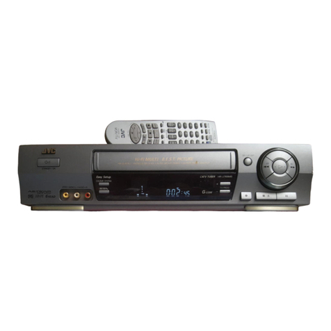
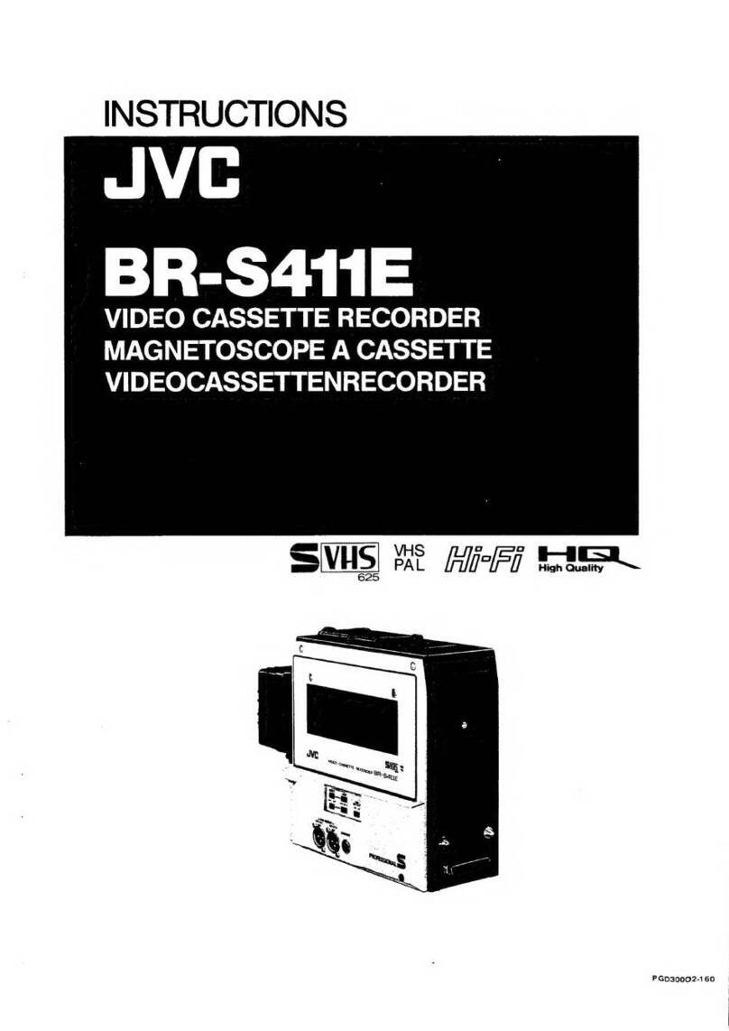
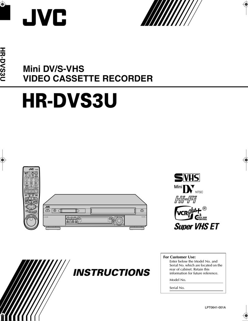
JVC BR-S622E User manual

INSTRUCTIONS
Jve
BR-S622E
VIDEO
CASSETTE
RECORDER
VIDEOKASSETTENREKORDER
MAGNETOSCOPE
A
CASSETTE
SVS)
82
A/F
.
PQD30002-284

SAFETY
PRECAUTIONS
Warning
Notice
FOR
YOUR
SAFETY
(Australia)
1.
Insert
this
plug
only
into
effectively
earthed
three-pin
power
outlet.
2.
If
any
doubt
exists
regarding
the
earthing,
consult
a
qualified
electrician.
3.
Extension
cord,
if
used,
must
be
three-core
correctly
wired.
IMPORTANT
(In
the
United
Kingdom)
Mains
Supply
(AC
240
V~)
WARNING
-
THIS
APPARATUS
MUST
BE
EARTHED
The
wires
in
this
mains
lead
are
coloured
in
accordance
with
the
following
code;
GREEN-and-
YELLOW:
EARTH
BLUE:
NEUTRAL
BROWN:
LINE
As
the
colours
of
the
wires
in
the
mains
lead
of
this
apparatus
may
not
correspond
with
the
coloured
markings
identifying
the
terminals
in
your
plug,
proceed
as
follows.
The
wire
which
is
coloured
GREEN-AND-YELLOW
must
be
connected
to
the
terminal
in
the
plug
which
is
marked
with
the
fetter
E
or
by
the
safety
earth
symbol
+
or
coloured
GREEN
or
GREEN-AND-YELLOW.
The
wire
which
is
coloured
BLUE
must
be
connected
to
the
terminal
which
is
marked
with
the
letter
N
or
which
is
coloured
BLACK.
The
wire
which
is
coloured
BROWN
must
be
connected
to
the
terminal
which
is
marked
with
the
letter
L
or
coloured
RED.
POWER
SYSTEM
Connection
to
the
mains
supply
The
operating
voltage
of
this
set
is
preset
to
220
~
240
V~
at
the
factory.
Before
connecting
to
mains,
check
that
the
voltage
selector
on
the
rear
panel
is
set
to
the
same
voltage
as
your
local
mains
supply.
Adapting
to
local
power
line
This
set
operates
on
110
—
127
V/220
—
240
V~
AC,
50/60
Hz.
If
the
preset
voltage
is
different
from
the
power
line
voltage
in
your
area,
reset
the
voltage
selector
by
inserting
a
screwdriver
into
the
slot
of
the
voltage
selector
and
turning
it
until
the
correct
voltage
is
displayed.
This
unit
is
produced
to
comply
with
Directives
76/889/EEC,
82/499/EEC,
87/308/EEC,
and
IEC
Publ.65.
WARNING:
TO
PREVENT
FIRE
OR
SHOCK
HAZARD,
DO
NOT
EXPOSE
THIS
APPLIANCE
TO
RAIN
OR
MOISTURE.
CAUTION
To
prevent
electric
shock,
do
not
open
the
cabinet.
No
user
serviceable
parts
inside.
Refer
servicing
to
qualified
service
personnel.
Note:
The
rating
plate
and
the
safety
caution
are
on
the
bottom
of
the
unit.
WARNING:
It
should
be
noted
that
it
may
be
unlawful
to
re-record
pre-
recorded
tapes,
records,
or
discs
without
the
consent
of
the
owner
of
copyright
in
the
sound
or
video
recording,
broadcast,
or
cable
programme
and
in
any
literary,
dramatic,
musical,
or
artistic
work
embodied
therein.

CONTENTS
How
to
Use
This
Manual
..............+0--
3
PFOCAUTIONS
wieceesssssssessscssssssnsssssssseseseneneeesesseoes
a
VCR
_
Video
Cassettes
POQUUI
OS:
sscciseiiceshtisteccistivsestotinicti
eeracataeiocnnee
4
Controls
and
Connectors
FORT
PAN)
icccecosictetccct
eben
ascents
5
Front
SUD-PAINEl
wiesessescsssscccesssessseeresesseseees
9
FREQ
PANGI
cvcseiacccsvscsseciosedossvacteoseveutsadenesensovice
117
Connections
VIdEO
EQUIDIMEN
wi.2:cissienccssesisrerasastsnenrsooes
13
AUCIO
EQUIDIMON
sa
covssicscecessecunconsssseensconssost
14
Reference
Sync
Signals
for
Recording
and
Playback............:cc00000+
15
Loading
and
Unloading
Video
CAaSSOHOS
cicc
ie
eda
antiaeiie
16
Loading
Unloading
Playback
PPS
A
OM
assis
cnssttetapcpacoccoctnannanceanisiocneen
17
PIOCOOUIO
Sioltit
das
olasiclecin
Sstetieneanecensest
Le
Shuttle
SCAICH
......:ccssesessccserssrsscsssessseerrecsers
18
JOG:
SCAN
oes
ssccusssncessssteasinnasinntanceenct
ntasteats
18
Rewind
and
Fast-FOrwatld
qu.
18
Recording
PPO
DIUPATONT
oi
ccsstscccinswspsusoidcontetatannresbiantateeieras
19
Recording
Level
Adjustments
...........
19
PPFOC
COUIE
sic
recstcsesibvteacssnasecsiessGoexssdsasuentasivaiess
20
Record-Pause
and
Assemble
EQN
siee
oceanic
canna
aan
20
AUCIO
DUDDIING
....ssssessseccceccnvecrsecrernensenens
21
On-Screen
DisplayS........1ccree
22
Counter
Display...
22
Time
Code/USer
Bits
.........1.::::sceccee
23
Time
Code
User
Bits
ID
Code
Time
Code
Editing
Time
Code/User
Bits
Recording/
Playback
PreSOt
FROCOLAING
uesssscrecssssscrsssarsarseessssneees
24
Regenerated
RECOlINAG
-v-ss-seseecreee
25
PIAVDACK:
si
iatsciecientetacdtsconc
stort
teats
Zo.
Setup
Menu
OD
CT
ANON
iy
aactectitatesteamiedlaenincnteevinnes
26
MGA
SOUINGS
sc.
crcsccssscssanncopressesarsnceestecnee
27
ROM
Version/Hour
Meter
Display...33
Warning
Display
..........-..:00cceeiteeteeee
35
TOSt
POINIS
sine
dena
canna
37
Automatic
Equaliser
.........2cccccceee
37
Installation
Rack
Mounting
(SA-K63UB)
......+0
38
Connector
Specifications
..........::008
39
SPCCIICATIONS
....ecssssecscsreecceeserieereenneenneenes
40

HOW
TO
USE
THIS
MANUAL
This
manual
introduces
you
to
the
BR-S622E
S-VHS
Recorder
and
shows
you
how
to
make
the
most
of
its
many
advanced
features.
Because
the
manual
is
written
for
the
person
who
has
some
experience
in
videotape
editing.and
is
familiar
with
the
terms
and
techniques
described,
explanations
and
definitions
are
kept
to
a
minimum.
Also,
some
functions
are
available
only
when
the
corresponding
optional
boards
are
plugged
in.
Whenever
these
functions
are
referred
to
in
the
text,
it
is
assumed
that
the
corresponding
boards
have been
installed.
@
TBC
functions
are
available
only
when
the
optional
SA-T22E
Time
Base
Corrector
boards
are
installed.
®
Component
Y/R-Y/B-Y
outputs
are
available
only
when
the
optional
SA-T22E
Time
Base
Corrector
boards
and
accom-
panying
component
output
connector
board
are
installed.
e
TC
functions
are
available
only
when
the
optional
SA-R22E
Time
Code
Reader/Generator
board
is
installed.
e
45-Pin
parallel
interface
is
possible
only
when
the
optional
SA-
K28E
Interface
board
is
installed.
e
RS-232C
interface
is
possible
only
when
the
optional
SA-
K27E
Interface
board
is
installed.
e@
Y/C
686/Y/C
924
Output
is
available
only
when
the
optional
SA-E92E
Output
board
is
installed.
IMPORTANT
Instructions
for
all
operations
are
based
on
the
setup
menu's
initial
settings
unless
otherwise
specified.
We
recommend
that
you
familiarise
yourself
with
the
available
—
settings
before
operating
the
VCR.
For
more
information,
please
refer
to
"Setup
Menu",
c>
p.26
PRECAUTIONS
®
Avoid
using
the
recorder
in
places
subject
to
the
following
conditions:
~
extreme
heat,
cold,
or
humidity,
—
dust,
—
vibrations,
and
—
poor
ventilation.
@
Be
careful
of
moisture
condensation.
Do
not
use
the
recorder
immediately
after
moving
it
from
a
cold
place
to
a
warm
place.
The
water
vapor
in
warm
air
will
condense
on
the
still-cold
video
head
drum
and
tape
guides
and
may
cause
damage
to
the
tape
and
the
recorder.
@
Handle
the
recorder
carefully.
*
Do
not
block
the
ventilation
openings.
*
Do
not
place
anything
heavy
on
the
recorder.
*
Do
not
place
anything
which
might
spill
on
the
top
cover
of
the
recorder.
*
Use
in
horizontal
(flat)
position
only.
¢
During
transportation,
*
Avoid
violent
shocks
to
the
recorder
during
packing
and
transportation.
*
Before
packing,
be
sure
to
remove
the
cassette
from
the
recorder.
This
recorder
uses
S-VHS,
S-VHS-C,
VHS,
and
VHS-C
cassettes.
Only
cassettes
recorded
in
the
standard
play
(SP)
mode
can
be
played
on
this
recorder.
LP
recording
is
not
possible.
S-VHS:
SE-180
for
180
minutes,
SE-120
for
120
minutes,
SE-60
for
60
minutes,
and
SE-30
for
30
minutes
of
recording.
S-VHS-C:
SE-C30
for
30
minutes
of
recording.
VHS:
E-180
for
180
minutes,
E-120
for
120
minutes,
E-90
for
90
minutes,
E-60
for
60
minutes,
and
E-30
for
30
minutes
of
recording.
VHS-C:
—EC-30
for
30
minutes
of
recording.
®
To
prevent
accidental
erasure,
remove
the
cassette's
safety
tab.
To
record
on
a
cassette
whose
safety
tab
has
been
removed,
cover
the
hole
with
adhesive
tape.
©
Before
loading
a
compact
cassette,
be
sure
the
tape
is
not
slack.
If
there
is
any
slack,
turn
the
gear
on
the
cassette
in
the
direction
of
the
arrow
to
take
up
the
slack.
®
Avoid
exposing
the
cassettes
to
direct
sunlight.
Keep
them
away
from
heaters.
e
Avoid
extreme
humidity,
violent
vibrations
or
shocks,
strong
magnetic
fields
(near
a
motor,
transformer
or
magnet),
and
dusty
places.
e
Place
the
cassettes
in
cassette
cases
and
position
vertically.
MHSTH
/
SWHsia

FEATURES
Newly-developed
full-size/compact-compatible
cassette
loading
mechanism
Similar
in
principle
to
the
loading
mechanisms
employed
in
M-Il,
3/4-inch,
and
other
high-performance
professional
equipment,
the
BR-S622E's
newly-developed
cassette
loading
mechanism
can
directly
accept
both
regular
and
C-
sized
S-VHS
cassettes.
The
tape
transport
system
has
also
been
improved
to
provide
faster
search
speeds
and
more
stable
transport.
C-size
S-VHS
cassettes
are
already
popular
in
image
acquisition
—
as
exemplified
by
the
success
of
JVC's
GY-X1
S-VHS-C
camcorder
—
and
are
expected
to
assume
a
more
important
role
in
distribution,
on-air
transmission,
and
other
applications.
Open-ended
system
architecture
with
plug-in
TC
and
TBC
capability
To
better
meet
the
requirements
of
different
edit
suites,
the
BR-S622E
has
been
designed
to
permit
open-ended
system
expansion.
Built-in
interfaces
are
provided
for
9-
pin
RS-422A
serial
remote,
COMPOSITE
IN/OUT,
and
Y/C443
IN/OUT.
Further
system
expansion
and
customisation
is
facilitated
by
a
variety
of
optional
"snap-in"
boards.
These
include
a
time
code
reader/generator
(LTC/VITC),
a
TBC
with
field
memory
and
COMPONENT
OUT
circuit,
as
well
as
a
45-pin
remote
control
board,
an
RS-232C
remote
control
board
for
connection
to
a
computer,
and
a
Y/C
686/Y/C
924
OUT
processor
board.
Since
these
circuit
boards
can
be
slotted
directly
into
the
BR-S822E,
it
can
easily
be
configured
to
fit
into
any
existing
system
without
the
need
for
expensive
alterations
or
additional
space.
High-quality
pictures
S-VHS
picture
quality
*
has
been
improved
still
further
with
the
addition
of
advanced
circuitry
including
a
digital
Y/C
separator
and
digital
DOC.
Moreover,
this
high
picture
quality
is
maintained
through
multi-generational
dubbing;
even
after
as
many
as
five
generations,
the
results
match
those
available
from
3/4-inch
equipment.
For
improved
playback
picture
performance,
noise
reduction
circuitry
and
switching
noise
masking
are
provided.
*
Technology
licensed
by
FAROUDJALaboaiores
.
*
Employs
chroma-enhancing
technology
co-developed
by
JVC
and
Laboratores
and
modified
for
S-VHS
applications.
Fully-equipped
for
high-performance
professional
edit
feeding
The
BR-S622E
is
equipped
with
a
comprehensive
set
of
studio-level
feeder
functions
such
as
colour
frame
servo,
auto
H-Phase
lock,
and
capstan
bump.
Search/jog
dials
are
also
provided
for
fast
and
accurate
location
of
edit
points
with
maximum
visual
search
speed
increased
to
32x.
Menu
Display
and
On-Screen
Mode
Check
For
easy
set-up
and
customisation,
the
BR-S622E
features
a
menu
display
which
allows
simple
dial
setting
and
switching
of
most
basic
functions
while
referring
to
indications
on
the
counter
display
or
on-screen.
As
a
result,
many
seldom-used
external
switches
have
been
eliminated.
Even
functions
normally
requiring
DIP
switch
resetting
can
be
switched
directly
via
the
menu
display.
On-screen
mode
check
and
warning
indications
are
also
provided.
Other
features
:
e
4-Field
sequence
colour
frame
servo
e
Hi-Fi
Stereo
system
with
Hyper-tangent
system
to
minimise
switching
noise
for
a
dynamic
range
of
more
than
87
dB
e
Two-channel
normal
audio
with
switchable
Dolby
B*
noise
reduction
©
Independent
audio
level
controls
for
all
four
channels
e
XLR
balanced
audio
connectors
©
Two
level
meters
switchable
between
Hi-Fi
and
Normal
audio;
the
right
meter
can
also
function
as
a
video
level/tracking
meter
e
Video
recording
level
control
8-Digit
time
counter
for
indication
of
editing
data
in
either
TC
or
CTL
mode
Built-in
black
burst
signal
generator
Wide-aspect
(16:9)
ID
recording
capability
External
sync
input
for
reference
video
Y-Frequency
response
control
Tiltable
control
panel
Heavy-duty
full-loading
mechanism
with
high-speed
chassis
Self-diagnostic
warning
system
Front-access
test
points
Automatic
head
cleaning
mechanism
9999-hour
meter
switchable
from
tape
counter
Headphone
jack
with
adjustable
level
output
19-inch
EIA
rack
mounting
Dolby
noise
reduction
manufactured
under
license
from
Dolby
Laboratories
Licensing
Corporation.
"DOLBY"
and
the
double-
D
symbol
OG
are
trademarks
of
Dolby
Laboratories
Licensing
Corporation.

CONTROLS
AND
CONNECTORS
JVC
Coma
es
ee
eee
Powe:
i
Auoam
besa
Src
MOEOPTRACKING
even
SELECT
oi
Ts
]
wean
T\\
Ay
aot
6
ee
AE
aS
Adhd
[|
Ssves
svse
l|
ee
fh
Ree
sunt
ws
&
CI
Se
te
7
CASSETTE
SE
Om
{soo}
1
3
=
(ean
pelle
=
|
(i)
HEH”
|
—
PROFESSIONAL
Ss
rr
r
—rcorr
V\
0G
SH
==
55
fase]
AUDIO
VIOEO
[MONITOR]
INPUT
COUNTER
REMOTE
|
HOLD
=
SHIFT
=
ADV
PRESET.
rey
i
ves
nf
wat]
ome
ue
©
oe
ire
ro
nee
=
\O
0
O0)|*
pagaeaaa
=
AUDIO
REC
LEVEL
—,
HiFi
——NORM——
apr
pz
i
ead
—
we
LEVEL
AUD-TL
AUD-2/R,
1
©
©
O
MADE
IN
JAPAN
POWER
switch
@
When
power
is
ON,
the
time
counter
and
level
meters
will
be
illuminated.
EJECT
button
with
LED
indicator
©
Ejects
the
cassette
(from
any
mode).
®
The
indicator
lights
while
the
cassette
is
being
ejected.
Cassette
loading
slot
@
Accepts
either
a
compact
or
full-size
S-VHS/VHS
cassette
according
to
the
type
selected
with
the
CASSETTE
SELECT
button
@.
LED
indicators
CASSETTE
SIZE
indicators
@
Indicate
whether
the
recorder
is
in
the
Full
or
Compact
mode.
When
all
three
indicators
are
blinking,
the
recorder
is
ready
to
accept
a
full-size
cassette.
When
only
the
centre
indicator
is
blinking,
the
recorder
is
ready
to
accept
a
compact
cassette.
Press
the
CASSETTE
SELECT
button
@
to
change
modes.
When
a
cassette
is
inserted,
the
blinking
will
stop
and
the
corresponding
indicator(s)
will
remain
continuously
lit.
AUTO
OFF
indicator
@
Lights
when
the
unit
malfunctions.
All
other
controls
are
disabied.
S-VHS
indicator
®
Lights
when
an
S-VHS
or
S-VHS-C
cassette
is
inserted
with
the
unit
in
the
S-VHS
mode,
or
when
playing
back
a
blank
part
of
the
tape.
®
Blinks
when
S-VHS
recording
is
attempted
with
a
VHS
cassette.
TBC
indicators
(with
optional
SA-T22E
TBC
installed)
OPERATE:
Lights
when
the
TBC
is
in
operation.
A
timebase-corrected
signal
is
output.
GENLOCK:
Lights
when
the
TBC
is
in
operation
and
locked
to
the
external
reference
signal.
SERVO
indicators
SERVOLOCK:
Lights
when
the
capstan
and
drum
servos
are
locked
to
the
reference
signal.
CTL
PULSE:
Lights
during
playback
of
a
tape
with
no
control
pulse
recorded.
COLOUR
FRAME:
Lights
when
the
capstan
and
drum
servos
are
locked
to
PAL
4-field
colour
frame.
AUDIO
indicators
Hi-Fi:
Lights
when
the
Hi-Fi
REC
circuit
is
ON
(via
menu
setting)
or
when
playing
back
Hi-Fi-recorded
tapes.
LIMITER:
Lights
when
the
built-in
audio
limiter
circuit
is
set
to
ON
(via
menu
setting).
NR:
Lights
when
the
Dolby
B*
noise
reduction
circuit
is
set
to
ON
(via
menu
setting).
TC
(TIME
CODE)
indicators
(with
optional
SA-R22E
TC
[time
code]
generator/reader
installed)
LTC:
Lights
green
when
LTC-recorded
tapes
are
played
back
with
the
normal
audio-2
track
set
for
LTC
use
(via
menu
setting).
If
LTC
is
not
picked
up,
the
indicator
lights
orange.
This
indicator
may
also
light
green
when
normal-audio-recorded
tapes
are
played
back.
VITC:
Lights
when
VITC-recorded
tapes
are
played
back
or
when
recording
a
VITC
signal.
TRACKING
conirol
e
Adjusts
tracking.
Turn
in
either
direction
until
the
tracking
meter
deflects
all
the
way
to
the
right.
e
Normally
leave
in
the
centre
click-stop
position.

CASSETTE
SELECT
button
e
Press
to
select
FULL
or
COMPACT.
The
corresponding
indicator(s)
will
light.
AUD-2/R
(VIDEO/TRACKING)
level
meter
®
Indicates
the
audio
level
of
the
normal
audio-2
or
Hi-Fi
right-channel
signal
during
recording
and
playback.
e
Functions
as
a
video
level
meter
during
recording
and
as
a
tracking
meter
during
playback
when
the
METER
SELECT
switch
@
is
set
to
VIDEO/TRACKING.
AUD-1/L
level
meter
@
Indicates
the
audio
level
of
the
normal
audio-1
or
Hi-Fi
left-
channel
signal
during
recording
and
playback.
METER
SELECT
switch
©
Switches
the
AUD-2/R
level
meter
@
between
audio
level
and
video
level
indication.
AUD-2/R:
Meter
functions
as
the
audio-2/Hi-Fi
right-channel
level
meter.
VIDEO/TRACKING:
Meter
functions
as
a
video
level
meter
in
recording,
and
as
a
tracking
meter
in
playback.
@
Tape
direction
indicators
®
Indicate
the
current
tape
direction.
[>
:
Forward
O
:
Still
<]
:
Reverse
JOG/SHUTTLE
dials
®
Dual
concentric
controls.
The
outer
functions
as
a
Shuttle
ting,
the
inner
as
a
Jog
dial.
The
Jog
and
Shuttle
modes
can
be
entered
directly
from
the
Play,
Still,
FF,
REW,
or
Stop
modes.
SHUTTLE
ring:
Search
speed
can
be
varied
continuously
from
1/30
to
32
times
normal
(up
to
14
times
normal
with
C-size
cassettes)
in
forward
or
reverse.
Set
to
the
centre
click-
stop
position
to
engage
the
Still
mode.
Manual
frame-by-frame
search
in
either
direction.
Tape
speed
is
determined
by
the
speed
of
dial
rotation.
Releasing
the
dial
engages
the
Still
mode.
Also
used
in
edit
point
trimming,
menu
setting
and
TC/UB
presetting.
JOG
dial:
Control
panel
lock
release
buttons
®
To
tilt
the
control
panel,
press
these
buttons
and
lift
the
panel
at
the
same
time.
The
panel
can
be
tilted
to
90°
and
locked
at
angles
of
25°,
50°,
and
75°.
JOG/SHUTTLE
button
with
JOG/SHTL
mode
indicators
@
Instantly
re-activates
the
Shuttle
mode
with
search
speed
determined
by
the
current
dial
setting.
Time
counter
©
Shows
tape
time
in
hours,
minutes,
seconds,
and
frames.
®
Displays
edit-in
and
-out
points.
©
Displays
user
bits.
®
Displays
menu
settings
and
warnings.
@®
Operation
buttons
with
LED
indicators
PAUSE/STILL
button
e
Temporarily
stops
recording
when
pressed
in
the
Record
mode.
@
Displays
a
still
picture
when
pressed
in
the
Play
mode.
PLAY
button
e
Starts
playback.
e
Re-starts
normal
playback
when
pressed
in
the
Still
or
Search
mode.
e
Starts
recording
when
pressed
together
with
the
REC
button.
e
Starts
audio
dubbing
when
pressed
together
with
the
AUD
DUB
button
in
the
Still
mode.
©
Re-starts
recording
when
pressed
in
the
Record-Pause
mode.
REC
button
e
Starts
recording
when
pressed
together
with
the
PLAY
button.
@
Outputs
EE
signals
when
pressed
in
the
Play
mode.
e
Displays
TC
generator
data
when
pressed
in
the
Stop
mode
with
REMOTE
select
switch
@
set
to
LOCAL.
(Released
by
pressing
STOP
button.)
AUD
DUB
button
e
Starts
audio
dubbing
when
pressed
together
with
the
PLAY
button.
STAND
BY
button
e
Switches
the
recorder
between
the
Standby-On
and
Standby-Off
modes
while
the
VCR
is
in
the
Stop
mode.
Standby-On
is
automatically
engaged
when
the
Stop
button
is
pressed.
Standby-On:
The
tape
is
loaded
and
the
drum
is
rotating:
The
indicator
is
lit.
Standby-Off:
The
tape
is
loaded
but
tape
tension
is
reduced
and
the
drum
does
not
rotate.
The
indicator
is
not
lit.
REW
button
e
Starts
rewind
when
pressed
in
any
mode.
STOP
button
e
Engages
the
Stop
mode
(Standby-On).
The
tape
stops,
but
remains
in
the
full-loaded
position
with
the
drum
rotating.
e@
The
STOP
and
STAND
BY
indicators
will
light.
FF
button
©
Starts
fast
forward
when
pressed
in
any
mode.
COUNTER
RESET
button
e
Resets
the
CTL
counter
to
zero.
©
The
CTL
counter
will
be
reset
even
if
this
button
is
pressed
in
the
TC
mode.

VIDEO
CassETTe
RECORDER
BR-SG622E
FRAME
"©
gaaaanea
AUD
‘STAND
BY
SiH
@
Time
Code
setting
buttons
To
preset
time
code/user
bit
data
(with
optional
SA-R22E
TC
generator/reader
installed).
HOLD
button
This
button
is
only
effective
when
the
SA-R22E's
PRESET/REGEN
switch
is
set
to
PRESET.
®
Holds
the
current
counter
data;
the
leftmost
digit
will
blink.
SHIFT
button
@
Shifts
the
blinking
digit
to
the
right.
(You
can
also
shift
the
blinking
digit
in
either
direction
by
holding
down
the
SHIFT
button
and
turning
the
JOG
dial.)
ADV
(ADVANCE)
button
e@
Advances
the
value
of
the
blinking
digit.
(You
can
also
change
the
value
in
either
direction
by
holding
down
the
ADV
button
and
turning
the
JOG
dial.)
PRESET
button
®
Transfers
the
data
set
with
the
HOLD,
SHIFT,
and
ADV
buttons
to
the
time
code
generator.
®
Automatically
cancels
the
Hold
mode.
®
MIC
jacks
(AUD-1/L,
AUD-2/R)
®
For
microphone
connection.
Input
signal
switches
from
line
to
microphone.
®
®
PHONES
jack/LEVEL
control
e
Connect
a
set
of
headphones
to
monitor
sound
recording.
@
Adjust
output
level
with
the
LEVEL
control.
Hi-Fi
L/R
and
NORM
AUD-1/AUD-2
AUDIO
REC
LEVEL
controls
®
To
separately
adjust
recording
levels
for
the
Hi-Fi
left/right-channel
signals
and
the
normal
(linear)
audio-1/2
signals.
e
Optimum
level
is
the
point
where
the
corresponding
meter’s
peak
deflection
is
"0".
@
AUDIO
MONITOR
select
switches
e
To
select
the
audio
output
for
the
PHONES
jack
and
the
AUDIO
MONITOR
OUT
connector.
e@
The
Hi-Fi/NORM
switch
also
switches
the
audio
level
meters
between
Hi-Fi
and
NORMAL.
Hi-Fi:
To
monitor
the
Hi-Fi
audio
signals.
NORM:
_
To
monitor
the
normal
audio
signals.
AUD-1/L:
To
monitor
the
normal
audio-1
or
Hi-Fi
left-
channel
signal.
MIX:
To
monitor
the
AUD-1/L
and
AUD-2/R
signals
together.
AUD-2/R:
To
monitor
the
normal
audio-2
signal
or
Hi-Fi
right-channel
signal.

@
VIDEO
INPUT
select
switch
e
To
select
an
input
video
signal
for
recording.
Y/C443:
To
record
the
signal
input
to
the
Y/C443
connector.
LINE:
To
record
the
signal
input
to
the
VIDEO
IN
LINE
connector.
BLACK:
To
record
the
internally-generated
black
burst
signal
on
a
blank
tape
in
preparation
for
insert
editing.
If
set
to
this
position
during
menu
setting,
on-screen
information
is
output
from
all
output
connectors,
not
only
the
MONITOR
OUT
connector.
@®
REMOTE
select
switch
®
To
select
between
remote
and
local
control
of
the
recorder.
9-PIN:
For
remote
control
via
the
rear
panel
9-pin
connector.
LOCAL:
For
direct
contro!
with
the
recorder's
function
buttons.
REM-2:
For
remote
control
via
the
optional
45-pin
or
RS-
232C
interface.
@
COUNTER
select
switch
®
To
select
the
time
counter
display
mode
with
the
SA-R22E
TC
generator/reader
installed.
If
this
is
not
installed,
CTL
signals
are
displayed
regardless
of
the
switch
setting.
CTL:
CTL
signals
are
displayed
on
the
time
counter.
TC:
Time
code
signals
are
displayed
on
the
time
counter.
UB:
User
bits
are
displayed
on
the
time
counter.

VIDEO
CaSsETTE
RECORDER
BR-S622E
SYESTA
id
CASSETTE
SIZE
Te
Om
a)
IRF
SNS
ORERATE
GEMLOCK
SMO
LOO
CHALE
HR
me
——_——,
UsMTER
TBC
CONTROLS
The
controls
in
this
section
function
when
the
optional
SA-T22E
TBC
(time
base
corrector)
is
installed.
@
VIDEO
LEVEL
UNITY/VARIABLE
select
switch/level
control
UNITY:
The
output
signal's
video
level
is
the
same
as
the
playback
signal.
Normally
set
to
this
position.
VARIABLE:
Allows
you
to
adjust
the
output
signal's
video
level
with
the
VIDEO
LEVEL
control.
Adjust-
ment
is
possible
within
+3
dB.
@
CHROMA
LEVEL
UNITY/VARIABLE
select
switch/level
control
UNITY:
The
output
signal's
chroma
level
is
the
same
as
the
playback
signal.
Normally
set
to
this
position.
VARIABLE:
Allows
you
to
adjust
the
output
signal's
chroma
level
with
the
CHROMA
LEVEL
control.
Adjust-
ment
is
possible
within
+3
dB.
©
CHROMA
PHASE
UNITY/VARIABLE
select
switch/level
control
UNITY:
The
output
signal's
chroma
phase
is
the
same
as
the
playback
signal.
VARIABLE:
Allows
you
to
adjust
the
output
signal's
chroma
phase
with
the
CHROMA
PHASE
control.
Adjustment
is
possible
within
+30°.
@
BLACK
LEVEL
VARIABLE/UNITY
select
switch/level
control
UNITY:
The
output
signal's
setup
level
is
the
same
as
the
playback
signal.
VARIABLE:
Allows
you
to
adjust
the
output
signal's
setup
level
with
the
BLACK
LEVEL
(SET
UP)
control.
Adjustment
is
possible
within
£107
mV.
@
SYSTEM
PHASE
control
®
Adjusts
the
output
signal's
horizontal
phase
with
respect
to
that
of
the
reference
input
signal.
Adjustment
is
possible
within
a
range
of
+3
psec.
@
SC
PHASE
e
Adjusts
the
output
signal's
subcarrier
phase
with
respect
to
that
of
the
reference
input
signal.
Up
to
15
rotations
are
possible
with
continuous
variation
over
a
range
of
+180°.
@
VIDEO
PHASE
conirol
®
Adjusts
the
output
signal's
video
phase
with
respect
to
the
playback
signal's
H
sync.
Up
to
15
rotations
are
possible
with
continuous
variation
over
a
range
of
+1.5
psec.
©
YC
TIMING
control
®
Adjusts
the
output
signal's
C
signal
delay
time
with
reference
to
the
Y
signal.
Adjustable
within
+500
nsec.
e
Normally
set
to
"8".

©
TBC
ON/OFF
switch.
®
Set
to
ON
for
TBC
playback.
(During
TBC
operation,
the
servo
is
locked
to
the
reference
signal
supplied
to
the
EXT
REF
connector
even
if
the
SYNC
select
switch
is
set
to
VIDEO.)
:
®
Set
to
OFF
to
bypass
TBC.
@
MENU
SET
ON/OFF
switch
e
SET
to
ON
to
activate
the
On-Screen
Menu.
The
counter
display
will
also
switch
to
the
Menu
Set
mode.
©
Most
basic
system
setup
operations
are
performed
using
the
Menu.
@
PB
Y
ENHANCE
switch
e
Enhances
the
luminance
signal
for
a
sharper
playback
picture.
+4
dB:
Boosts
luminance
signal
level
by
4
dB
at
2.5
MHz
for
maximum
picture
sharpness.
+2
dB:
Boosts
luminance
signal
level
by
2
dB
at
2.5
MHz
for
a
sharper
picture.
0
dB:
No
effect.
The
same
result
is
obtained
by
setting
the
VIDEO
OUT
select
switch
@
to
EDIT.
@
SYNC
select
switch
EXT:
The
servo
is
synchronised
with
the
external
reference
signal
supplied
to
the
EXT
REF
input.
VIDEO:
The
servo
is
synchronised
with
the
input
video
signal.
@
REC
MODE
select
switch
S-VHS:
To
record
in
the
S-VHS
mode.
(Use
S-VHS
cassettes
only)
VHS:
To
record
in
the
VHS
mode.
@
VIDEO
OUT
select
switch
EDIT:
Set
to
this
position
when
using
this
VCR
as
a
feeder
or
recorder
in
dubbing.
NORM:
Normally
set
to
this
position.
@®
VIDEO
AGC
ON/OFF
switch
@
Set
to
ON
to
activate
the
built-in
VIDEO
AGC
circuit.
e
Set
to
OFF
to
adjust
the
luminance
video
recording
level
manually.
@®
VIDEO
control
e
Use
to
adjust
video
recording
level,
referring
to
the
VIDEO/TRACKING
meter.
The
centre
click-stop
is
the
standard
position.
The
VIDEO
AGC
switch
must
be
OFF
to
use
this
control.
TIME
CODE
GENERATOR/READER
SETTING
SWITCHES
_
(With
SA-R22E
TC
generator/reader
installed)
@
ID
PRESET
ON/OFF
switch
ON:
To
record
the
ID
code
specifically
preset
for
each
VCR.
OFF:
To
use
the
user
bits
memory
for
standard
procedures
in
the
Preset
mode.
@®
VITC
REC
ON/OFF
switch
ON:
To
record
VITC
time
codes.
OFF:
VITC
time
codes
are
not
recorded.
NOTE:
This
switch
has
no
effect
on
LTC
recording
(enabled
by
setting
menu
item
#206
to
"01
-
LTC’).
@
FREE/REC
switch
This
switch
is
effective
only
when
the
PRESET/REGEN
switch
is
set
to
PRESET
and
the
INT/EXT
switch
is
set
to
INT.
FREE:
The
time
code
runs
in
real
time,
regardless
of
the
video
recorder's
operating
mode.
REC:
The
time
code
runs
only
during
recording.
PRESET/REGEN
switch
PRESET:
To
use
the
internal
TC
generator
in
the
Preset
mode
(with
the
INT/EXT
switch
set
to
INT),
or
to
use
an
external
TC
generator
via
the
TIME
CODE
IN
connector
(with
the
INT/EXT
switch
set
to
EXT).
REGEN:
To
use
the
internal
TC
generator
in
sync
with
either
the
playback
time
codes
(with
the
INT/EXT
switch
set
to
INT),
or
externally
input
time
codes
(with
the
INT/EXT
switch
set
to
EXT).
INT/EXT
switch
INT:
To
use
the
internal
TC
generator.
-
EXT:
To
use
an
externally-connected
LTC/VITC
generator.
AUTO/LTC/VITC
switch
e
To
select
the
TC
reader
mode.
Select
the
mode
according
to
the
type
of
reference
time
code
with
which
the
internal
TC
generator
is
synchronised
in
the
Regen
mode.
AUTO:
For
tapes
with
matching
VITC
and
LTC
data.
Counts
time
codes
in
VITC
at
tape
speeds
lower
than
normal,
and
in
LTC
at
speeds
higher
than
normal.
Missing
sections
are
interpolated
with
CTL
counts.
LTC:
For
LTC-only
tapes
or
when
editing
with
LTC
data.
Counts
time
codes
in
CTL
at
tape
speeds
lower
than
norma!
and
higher
than
10
times
normal,
and
in
LTC
at
speeds
higher
than
normal.
Missing
sections
are
interpolated
with
CTL
counts.
VITC:
For
VITC-only
tapes
or
when
editing
with
VITC
data.
Counts
time
codes
in
VITC
at
tape
speeds
lower
than
10
times
normal,
and
in
CTL
at
speeds
higher
than
10
times
normal.
Missing
sections
are
interpolated
with
CTL
counts.
Test
points
V-RF
test
point
®
Outputs
the
video
head
FM
signal
during
playback.
e
Can
be
used
for
detection
of
clogged
or
worn
heads.
A-RPF
test
point
@
Outputs
the
Hi-Fi
audio
FM
signal
during
playback.
©
Can
be
used
for
detection
of
clogged
or
worn
heads.
D-PULSE
pin
e
Connect
to
the
external
trigger
terminal
of
an
oscilloscope.
GND
@
Connect
to
the
ground
terminal
of
an
oscilloscope.
10

11
Apparpten
far
¢ndast
axsiutas
till
j
‘dat
natuttag.
ote
recucto]
menutacifed
once]
teense
ny
Laer
Cowpens
CB
aN
2E
WA
VOLTAGE
SELECTOR
NOV-127¥
220V-240V
FUSE,
FrT4a
WARNING:
DAI
@
AC
IN
socket
®
Connect
to
110
—
120
V
or
220
—
240
V
AC,
50/60
Hz
power
outlet.
@
Fuse
holder
©
NORM
AUDIO
INPUT
impedance
select
switch
ON:
600
ohms.
:
OFF:
10k-ohms.
Normally
set
to
this
position.
@
Audio
input
connectors
AUDIO
INNORMAL:
Normal
audio
input
connectors
for
Audio-1
and
Audio-2.
Hi-Fi
audio
input
connectors
for
Left
and
Right.
@
Audio
output
connectors
AUDIO
QUT
NORMAL:
Normal
audio
output
connectors
for
Audio-1
and
Audio-2.
Hi-Fi
audio
output
connectors
for
Left
and
Right.
©
Hi-Fi
AUDIO
INPUT
impedance
select
switch
ON:
600
ohms.
OFF:
10k-ohms.
Normally
set
to
this
position.
@,
©
VIDEO
OUT
LINE
(1,
2)
connectors
®
The
composite
video
signal
is
output
from
these
connectors.
©,
®
VIDEO
OUT
Y/C443
(1,
2)
connectors
®
The
Y/C443
signal
is
output
from
these
connectors.
@
AUDIO
MONITOR
OUT
connector
®
The
audio
signal
selected
with
the
AUDIO
MONITOR
select
switches
is
available
at
this
connector.
AUDIO
IN
Hi-Fi:
AUDIO
OUT
Hi-Fi:
>
e@ee)|
US
VOLTAGE
ey
te
‘Der
Lnborrtorad
ticorann
torper
WARNING:SHDCK
WAZARD-00
ROT
OPEN
AVIS:
RISQUE
DE
CHOC
ELECTRIGUE-NEPAS
OUVRIR.
VIDEO
MONITOR
OUT
connector
e@
The
composite
video
output
signal
is
available
at
this
connector.
On-screen
information
is
also
supplied.
Expansion
slot
©
For
installation
of
optional
interface
(SA-K28E
or
SA-
K27E).
NORMAL
INPUT
LEVEL
select
switch
©
To
select
-6
dB,
0
dB,
or
+4
dB
according
to
the
level
of
the
normal
audio
input
signal.
Both
channels
are
switched
simultaneously.
Hi-Fi
INPUT
LEVEL
select
switch
©
To
select
-6
dB,
0
dB,
or
+4
dB
according
to
the
level
of
the
Hi-Fi
audio
input
signal.
Both
channels
are
switched
simultaneously.
AUDIO
INPUT
SELECT
switch
H
COM:
"Hi-Fi
Combined”
recording.
Set
to
this
position
to
record
audio
signals
input
to
the
AUDIO
IN
Hi-Fi
connectors
on
both
the
Hi-Fi
and
Normal
audio
tracks.
SEP:
"Separate"
recording.
Set
to
this
position
to
record
audio
signals
input
to
the
AUDIO
IN
Hi-Fi
and
NORMAL
connectors
separately
on
the
Hi-Fi
and
Normal
audio
tracks.
N
COM:
"Normal
Combined"
recording.
Set
to
this
position
to
record
audio
signals
input
to
the
AUDIO
IN
NORMAL
connectors
on
both
the
Hi-Fi
and
Normal
audio
tracks.

@
TBC
ON/OFF
switch.
@
Set
to
ON
for
TBC
playback.
(During
TBC
operation,
the
servo
is
locked
to
the
reference
signal
supplied
to
the
EXT
REF
connector
even
if
the
SYNC
select
switch
is
set
to
VIDEO.)
©
Set
to
OFF
to
bypass
TBC.
@
MENU
SET
ON/OFF
switch
e
SET
to
ON
to
activate
the
On-Screen
Menu.
The
counter
display
will
also
switch
to
the
Menu
Set
mode.
©
Most
basic
system
setup
operations
are
performed
using
the
Menu.
@
PB
Y
ENHANCE
switch
@
Enhances
the
luminance
signal
for
a
sharper
playback
picture.
+4
dB:
Boosts
luminance
signal
level
by
4
dB
at
2.5
MHz
for
maximum
picture
sharpness.
+2
dB:
Boosts
luminance
signal
level
by
2
dB
at
2.5
MHz
for
a
sharper
picture.
0
dB:
No
effect.
The
same
result
is
obtained
by
setting
the
VIDEO
OUT
select
switch
@
to
EDIT.
@
SYNC
select
switch
EXT:
The
servo
is
synchronised
with
the
external
reference
signal
supplied
to
the
EXT
REF
input.
VIDEO:
The
servo
is
synchronised
with
the
input
video
signal.
@
REC
MODE
select
switch
S-VHS:
To
record
in
the
S-VHS
mode.
(Use
S-VHS
cassettes
only)
VHS:
To
record
in
the
VHS
mode.
@
VIDEO
OUT
select
switch
EDIT:
_
Set
to
this
position
when
using
this
VCR
as
a
feeder
or
recorder
in
dubbing.
NORM:
Normally
set
to
this
position.
@®
VIDEO
AGC
ON/OFF
switch
®
Set
to
ON
to
activate
the
built-in
VIDEO
AGC
circuit.
©
Set
to
OFF
to
adjust
the
luminance
video
recording
level
manually.
@®
VIDEO
control
e
Use
to
adjust
video
recording
level,
referring
to
the
VIDEO/TRACKING
meter.
The
centre
click-stop
is
the
standard
position.
The
VIDEO
AGC
switch
must
be
OFF
to
use
this
control.
TIME
CODE
GENERATOR/READER
SETTING
SWITCHES
“(With
SA-R22E
TC
generator/reader
installed)
@
ID
PRESET
ON/OFF
switch
ON:
To
record
the
ID
code
specifically
preset
for
each
VCR.
OFF:
To
use
the
user
bits
memory
for
standard
procedures
inthe
Preset
mode.
@®
VITC
REC
ON/OFF
switch
ON:
‘Torecord
VITC
time
codes.
OFF:
VITC
time
codes
are
not
recorded.
NOTE:
This
switch
has
no
effect
on
LTC
recording
(enabled
by
setting
menu
item
#206
to
"01
—
LTC").
@
FREE/REC
switch
This
switch
is
effective
only
when
the
PRESET/REGEN
switch
is
set
to
PRESET
and
the
INT/EXT
switch
is
set
to
INT.
FREE:
The
time
code
runs
in
real
time,
regardless
of
the
video
recorder's
operating
mode.
REC:
The
time
code
runs
only
during
recording.
PRESET/REGEN
switch
PRESET:
To
use
the
internal
TC
generator
in
the
Preset
mode
(with
the
INT/EXT
switch
set
to
INT),
or
to
use
an
external
TC
generator
via
the
TIME
CODE
IN
connector
(with
the
INT/EXT
switch
set
to
EXT).
REGEN:
To
use
the
internal
TC
generator
in
sync
with
either
the
playback
time
codes
(with
the
INT/EXT
switch
set
to
INT),
or
externally
input
time
codes
(with
the
INT/EXT
switch
set
to
EXT).
INT/EXT
switch
INT:
To
use
the
internal
TC
generator.
-
EXT:
To
use
an
externally-connected
LTC/VITC
generator.
AUTO/LTC/VITC
switch
e
To
select
the
TC
reader
mode.
Select
the
mode
according
to
the
type
of
reference
time
code
with
which
the
internal
TC
generator
is
synchronised
in
the
Regen
mode.
AUTO:
For
tapes
with
matching
VITC
and
LTC
data.
Counts
time
codes
in
VITC
at
tape
speeds
lower
than
normal,
and
in
LTC
at
speeds
higher
than
normal.
Missing
sections
are
interpolated
with
CTL
counts.
LTC:.
For
LTC-only
tapes
or
when
editing
with
LTC
data.
Counts
time
codes
in
CTL
at
tape
speeds
lower
than
normal
and
higher
than
10
times
normal,
and
in
LTC
at
speeds
higher
than
normal.
Missing
sections
are
interpolated
with
CTL
counts.
VITC:
For
VITC-only
tapes
or
when
editing
with
VITC
data.
Counts
time
codes
in
VITC
at
tape
speeds
lower
than
10
times
normal,
and
in
CTL
at
speeds
higher
than
10
times
normal.
Missing
sections
are
interpolated
with
CTL
counts.
Test
points
V-RF
test
point
e
Outputs
the
video
head
FM
signal
during
playback.
©
Can
be
used
for
detection
of
clogged
or
worn
heads.
A-FF
test
point
@
Outputs
the
Hi-Fi
audio
FM
signal
during
playback.
e
Can
be
used
for
detection
of
clogged
or
worn
heads.
D-PULSE
pin
©
Connect
to
the
external
trigger
terminal
of
an
oscilloscope.
GND
e
Connect
to
the
ground
terminal
of
an
oscilloscope.
10

II
Apparpten
far
¢ndast
aqsiutas
till
dat
natuttag.
d
vl
s.
AC
HOV-127V/:
NO.
oP
|
RE
-SB22E/
/-240V}-50/60HZ
R
9225
VOLTAGE
SELECTOR
oF
oF
TOv-127V
220V-240V
FUSE
fa
|
°
FiTaa
|
|
WARNING:
D.
be
@
AC
IN
socket
©
Connect
to
110
—
120
V
or
220
—
240
V
AC,
50/60
Hz
power
outlet.
@
Fuse
holder
©
NORM
AUDIO
INPUT
impedance
select
switch
ON:
600
ohms.
:
OFF:
10k-ohms.
Normally
set
to
this
position.
©
Audio
input
connectors
AUDIO
INNORMAL:
Normal
audio
input
connectors
for
Audio-1
and
Audio-2.
Hi-Fi
audio
input
connectors
for
Left
and
Right.
©
Audio
output
connectors
AUDIO
QUT
NORMAL:
Normal
audio
output
connectors
for
Audio-1
and
Audio-2.
Hi-Fi
audio
output
connectors
for
Left
and
Right.
@
Hi-Fi
AUDIO
INPUT
impedance
select
switch
ON:
600
ohms.
OFF:
10k-ohms.
Normally
set
to
this
position.
@,
©
VIDEO
OUT
LINE
(1,
2)
connectors
®
The
composite
video
signal
is
output
from
these
connectors.
O,
@
VIDEO
OUT
Y/C443
(1,
2)
connectors
©
The
Y/C443
signal
is
output
from
these
connectors.
@
AUDIO
MONITOR
OUT
connector
e
The
audio
signal
selected
with
the
AUDIO
MONITOR
select
switches
is
available
at
this
connector.
AUDIO
IN
Hi-Fi:
AUDIO
OUT
Hi-Fi:
ROUS
VOLTAGE
INS{DE.
TIME
CODE
O)>r
e
=
OPIN
WARNING:SHOCK
WAZARD-00
HOT
OPEX.
ANAS:
RrSOUE
DE
CHOC
ELECTRIQUE-NEPAS
OUVRIR
VIDEO
IN
EXT
REF
UNE
weaas
OPTIDN
7
oe
©)
LQG
©)
‘on
NZ
A
750.
1504
&
as
=
2
tS
@
Cmontror
our]
VIDEO
OUT
@
VIDEO
MONITOR
OUT
connector
©
The
composite
video
output
signal
is
available
at
this
connector.
On-screen
information
is
also
supplied.
@®
Expansion
slot
©
For
installation
of
optional
interface
(SA-K28E
or
SA-
K27E).
@
NORMAL
INPUT
LEVEL
select
switch
©
To
select
-6
dB,
0
dB,
or
+4
dB
according
to
the
level
of
the
normal
audio
input
signal.
Both
channels
are
switched
simultaneously.
@®
Hi-Fi
INPUT
LEVEL
select
switch
e
To
select
-6
dB,
0
GB,
or
+4
dB
according
to
the
level
of
the
Hi-Fi
audio
input
signal.
Both
channels
are
switched
simultaneously.
@
AUDIO
INPUT
SELECT
switch
H
COM:
"Hi-Fi
Combined"
recording.
Set
to
this
position
to
record
audio
signals
input
to
the
AUDIO
IN
Hi-Fi
connectors
on
both
the
Hi-Fi
and
Normal
audio
tracks.
SEP:
"Separate"
recording.
Set
to
this
position
to
record
audio
signals
input
to
the
AUDIO
IN
Hi-Fi
and
NORMAL
connectors
separately
on the
Hi-Fi
and
Normal
audio
tracks.
N
COM:
"Normal
Combined"
recording.
Set
to
this
position
to
record
audio
signals
input
to
the
AUDIO
IN
NORMAL
connectors
on
both
the
Hi-Fi
and
Normal
audio
tracks.

AUDIO
OUTPUT
LEVEL
select
switch
@
To
select
-6
dB,
0
dB,
or
+4
dB
according
to
the
input
level
of
connected
audio
equipment.
All
four
audio
channels
are
switched
simultaneously.
TIME
CODE
IN/OUT
connectors
Set
menu
item
#206
to
“01
—
LTC"
to
record
LTC
time
codes
on
the
normal
audio-2
track.
©
Connect
a
time
code
generator
to
the
IN
connector
for
external
time
code
recording.
e
Connect
a
time
code
reader
to
the
OUT
connector
for
external
time
code
reading.
VIDEO
IN
LINE
connectors
®
The
composite
video
signal
is
input
to
the
left
connector.
e
To
output
the
loop-through
signal
to
another
unit,
set
the
75-ohm
terminating
switch
to
OFF.
75-Ohm
terminating
switch
ON:
The
loop-through
signal
is
terminated
at
the
BR-S622E.
OFF:
The
loop-through
signal
is
output
to
another
unit.
9-PIN
connector
©
Connect
to
an
RS-422
9-pin
serial
remote
control
unit
or
to
the
RS-422
9-pin
connector
of
a
recorder
for
swap
editing.
VIDEO
IN
Y/C443
connector
®
The
Y/C443
signal
is
input
to
this
connector.
®
8e
@
OPTION
connector
©
Delivers
the
Y/C
686/Y/C
924
signal
(with
optional
SA-
E92E
Output
board
installed)
to
the
DUB
IN
connector
of
3/4"
U-VCR
machines.
EXT
REF
connectors
with
75-ohm
terminating
switch
e
Supply
the
reference
signal
(either
black
burst
signal
or
composite
video)
to
the
left
connector
and
set
the
75-ohm
terminating
switch
to
ON.
©
To
output
a
loop-through
signal
to
another
unit,
set
the
75-
ohm
terminating
switch
to
OFF.
NOTE:
@
When
using
the
SA-T22E,
do
not
use
a
black-and-white
signal
or
sync
signal
without
burst
as
the
reference
signal,
otherwise
the
intended
synchronisation
will
not
be
obtained.
Fans
Expansion
slot
For
installation
of
COMPONENT
OUT
connector
board
when
optional
SA-T22E
TBC
is
installed.
e
Y/R-Y/B-Y
output
connectors:
Mil
or
Betacam
component
signal
is
output.
e
TBC
remote
terminal:
Connect
a
15-pin
remote
controller
for
TBC
operation.
VOLTAGE
SELECTOR
e
Select
voltage
according
to
your
local
power
supply.
(Be
sure
the
POWER
is
off
when
setting
the
voltage.)
12

13
CONNECTIONS
VIDEO
CAMERA
VIDEO
OUT
Y/C443
OUT
VIDEO
CAMERA
VIDEO
IN
LINE
VIDEO
IN
BR-S622E
Y/R-Y/B-Y
oag|
COMPONENT
|22.2'33824528'@,
*
Illustration
shows
rear
panel
with
SA-T22E
installed.
VIDEO
OUT
LINE
MONITOR
OUT
MONITOR
AC
110
-
127/
220-240
V
50/60Hz
NOTES:
@
To
output
the
loop-through
signal,
set
the
75-ohm
terminating
switch
to
OFF,
otherwise
set
it
to
ON.
(Be
sure
to
terminate
the
signal
at
the
last
of
the
connected
units.)
@
On-screen
information
is
output
from
the
VIDEO
MONITOR
OUT
connector
only.
e
Y/R-Y/B-Y
component
signals
can
be
output
when
the
optional
TBC
board
SA-T22E
is
installed.
M-ll
and
Betacam
component
signals
are
selectable
via
menu
item
#104.
(c=
p.28)

MONITOR
OUT
MONITOR
AC
~110-127/
220
—
240
V
50/60Hz
FRONT
PANEL
7-7
AUDIO
REC
LEVEL
—
Hi-Fi
NORM
—
AUO-1
AUD-2
L
Rg
ongne
o-oo
o-fn0
o-S-p
Lease
oo
os
es
velar
PHONES
Sa
Run.
AUD-V/L
AUD-2/R
ote
ofa
ne
Cc}
10:
e
HEADPHONE
MIC MIC
NOTES:
e
The
MIC
jack
has
priority
over
the
rear
pane!
AUDIO
IN
connectors.
When
a
microphone
is
connected,
the
input
signal
is
automatically
shifted
from
AUDIO
IN
to
MIC.
14

REFERENCE
SYNC
SIGNALS
FOR
RECORDING
AND
PLAYBACK
START
PLAY
Locked
to
the
Setting
ON
advanced
sync
of
the
TBC
are
signal
from
the
switch.
:
TBC
board.
REC
OFF
EXT
Setting
VIDEO
of
the
SYNC
switch.
PLAY
REC
or
REC
Setting
of
Y/C443
the
VIDEO
INPUT
switch.
Is
the
SYNC
signal
ap-
plied
to
EXT
REF
connector?
Is
the
SYNC
signal
ap-
plied
to
EXT
REF
connector?
Is
the
input
video
signal
applied
to
LINE
IN
connector?
Is
the
input
video
signal
applied
to
Y/C443
connector?
YES
YES
LINE
Setting
of
the
VIDEO
INPUT
switch.
Y/C443
Locked
to
the
input
video
signal
applied
to
Locked
to
the
Locked
to
the
Locked
to
the
Locked
to
the
Locked
to
the
external
syne
external
syne
external
sync
input
video
built-in
sync
signal
applied
to
signal
signal
applied
to
signal
apolles
to
signal
applied
to
é
the
Y/C443
connector
without
delay.
the
EXT
REF
the
EXT
REF
the
EXT
REF
connector
with
connector
with
connector
1H
advance.
1H
delay.
without
delay.
the
LINE
IN
|
generator.
connector
with
1H
delay.

LOADING
AND
UNLOADING
VIDEO
CASSETTES
1.
Switch
on
the
power.
2,
Check
the
AUTO
OFF
indicator.
e
If
this
indicator
lights,
some
abnormal
condition
such
as
condensation
has
occurred.
All
functions
except
Eject
are
disabled.
3.
Check
the
CASSETTE
SIZE
indicators.
@
If
you're
loading
a
full-size
cassette,
be
sure
that
all
three
indicators
are
blinking.
@
If
you're
loading
a
compact
cassette,
be
sure
that
only
the
centre
indicator
is
blinking.
e
Press
the
CASSETTE
SELECT
button
to
change
modes.
4.
Insert
a
cassette
with
its
label
side
facing
you.
e
The
cassette
is
automatically
retracted
and
loaded.
®
The
VCR
enters
the
Stop/Standby-On
mode.
The
STOP
and
STAND
BY
indicators
will
light.
In
this
mode,
the
tape
is
fully
loaded
and
the
head
drum
is
rotating.
The
CASSETTE
SIZE
indicator(s)
will
stop
blinking
but
remain
iluminated.
©
Output
signal
changes
from
EE
to
playback.
NOTES:
e
Be
sure
that
the
CASSETTE
SIZE
indicator(s)
is
blinking
when
inserting
a
cassette.
5.
To
cancel
the
Standby-On
mode,
press
the
STAND
BY
button.
@
The
head
drum
will
stop
rotating,
but the
tape
remains
in
the
full-loaded
position.
The
STAND
BY
indicator
will
go
out.
e
As
soon
as
you
engage
another
mode
(Play,
Rewind,
Fast
Forward,
Record,
etc.),
the
STAND
BY
indicator
will
come
on
again.
1.
Press
EJECT.
e
The
cassette
is
ejected
automatically.
@
You
can
press
the
EJECT
button
in
any
mode.
®
Output
signal
changes
from
playback
to
EE.
‘2.
Remove
the
cassette.
WARNING
©
Do
not
insert
fingers
or
foreign
objects
into
the
cassette
loading
slot
as
this
may
result
in
personal
injury
or
damage
to
the
mechanism.
©
Do
nottry
to
remove
the
cassette
once
automatic
loading
has
started.
CASSETTE
SIZE
indicators
CASSETTE
SELECT
button
AUTO
OFF
indicator
=
Sao
‘Ss
—
M00
FEC
LEV
—
EJECT
button
vibEO
casseTre
RecoRDENR
BR~S622E
STAND
BY
button
16

PLAYBACK
1.
Set
the
SYNC
select
switch
as
required.
(c=
p.10)
2.
Set
the
AUDIO
MONITOR
select
switches
as
required.
(c¥
p.8)
3.
Set
the
COUNTER
select
switch
as
required.
(c=
p.8)
4.
Set
the
VIDEO
OUT
select
switch
as
required.
NOR:
for
normal
playback.
EDIT:
when
using
the
VCR
as
an
edit
feeder.
5.
Set
the
REMOTE
select
switch
as
required.
(c=
p.8)
6.
Set
the
TBC
switch
to
ON
if
you
are
using
the
SA-T22E
or
an
external
TBC.
1.
Press
the
PLAY
button.
@
Normal
playback
starts.
2.
Check
the
tracking
level.
@
Set
the
METER
SELECT
switch
to
VIDEO/TRACKING.
@
Adjust
the
TRACKING
control
until
the
tracking
meter
(AUD-2/R)
deflects
fully
to
the
right.
@
Check
the
monitor
screen
to
be
sure
that
the
picture
is
not
blurred
or
marred
by
noise
bars.
3.
Set
the
PB
Y
ENHANCE
switch
as
required.
@
lf
the
VIDEO
OUT
select
switch
is
set
to
EDIT,
this
switch
has
no
effect.
4.
Press
the
STOP
button
to
stop
playback.
NOTES:
@
LP
recordings
cannot
be
played
back.
®
To
monitor
the
input
signal
during
playback,
press
the
REC
button
while
in
the
Play
mode.
e
Do
not
press
the
REC
and
PLAY
buttons
simultaneously,
otherwise
the
VCR
will
enter
the
Record
mode.
The
VCRis
preset
to
enter
the
Stop
mode
at
tape
end.
If
you
want
the
VCR
to
automatically
rewind
when
the
end
of
the
tape
is
reached,
set
menu
item
#312
to
"01
—
REW".
(cz
p.29)
17
AUDIO
MONITOR
select
switches
COUNTER
select
switch
REMOTE
select
switch
SYNC
select
switch
VIDEO
OUT
select
switch
METER
SELECT
switch
PLAY
button
STOP
button
PB
Y
ENHANCE
switch
|
|
Table of contents
Other JVC VCR System manuals

JVC
JVC HR-J271MS User manual

JVC
JVC HR-J615EG User manual

JVC
JVC LPT0641-001A User manual

JVC
JVC HR-S4500U User manual

JVC
JVC BR-DV6000E User manual

JVC
JVC BR-DV3000U - Professional Editing Video Cassete... User manual

JVC
JVC HR-J7005UM User manual

JVC
JVC HR-J648EH, HR-J648E, HR-J448E, User manual

JVC
JVC HR-DD445EK User manual

JVC
JVC HR-VP770U User manual