equipment key 7
Diagram Key
REAR PANEL
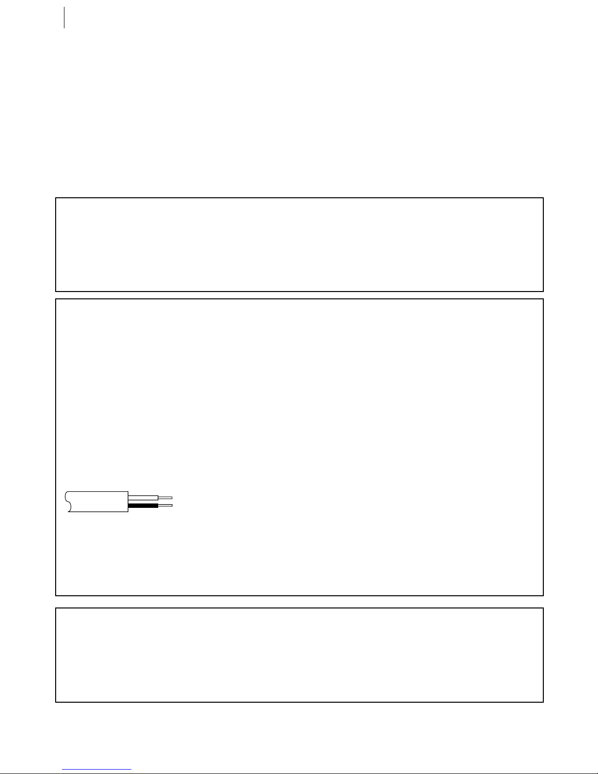
1Ma ns Power Cord supplies
power to VCR.
2AV1 (L-1) IN/OUT Connector
enables AV connection to TV or
second VCR; input recordable
when L-1 selected.
3SAT CONTROL Connector
enables connection of the
provided atellite Controller for
timer recording with a satellite
receiver.
4ANT. IN Connector enables
connection of aerial.
5AV2 (L-2) IN/DECODER
Connector enables connection of
satellite receiver or second
recorder; input recordable when
L-2 selected.
6AUDIO OUT (L/R) Connectors
enable connection of audio
cassette recorder, TV or second
VCR for dubbing.
7RF OUT Connector enables
connection to aerial terminal of TV
receiver.
VCR DISPLAY PANEL
1B.E.S.T. P cture System
D splay lights from bottom to top
while B.E. .T. is active.
2Symbol c Mode Ind cators
Play:
Fast-forward/rewind
variable search:
Still:
Slow:
Record:
Record pause:
3Tape Speed Ind cators
display mode of recording; light
during Record or Play mode.
4Programme Start T me
Ind cator ( ) shows the
programme start time.
Programme Stop T me
Ind cator ( ) shows the
programme stop time.
5c Ind cator lights when the c
button has been pressed to
engage Timer mode.
6Tape Rema n ng T me
Ind cator displays time
remaining on tape when certain
buttons are pressed.
7Channel D splay shows preset
position where the station
currently being received is stored.
Clock D splay shows current
time.
Counter, Preset Position (or
Mode)*, Clock and Tape
Remaining Time Display appear
alternately when the – –:– –
(Display) button is pressed.
* Preset Position is not displayed
during playback.
8REVIEW Ind cator blinks after
timer-recording and shows how
many programmes have been
timer-recorded.
9PDC Ind cator lights when
PDC has been engaged for timer
recording.
* VPS (Video Programme System)
recording is not currently available in
the U.K. and not possible with this
V R.
10 S-VHS Ind cator lights when
a cassette marked -VH is
inserted with -VH mode set to
‘ON’, when an -VH -recorded
tape or -VH ET-recorded tape
is played back, or when -VH
ET mode is engaged.
11 VCR Ind cator lights when the
VCR is in the video mode. At this
point, the TV automatically enters
AV mode.
12 ‘Cassette Loaded’ Mark
lights once a cassette is
inserted; remains lit until
cassette ejected.
13 Counter shows time elapsed
since playback or recording
began.
With v displayed, shows
time remaining from current tape
position to end of tape.
Counter, Preset Position (or
Mode)*, Clock and Tape
Remaining Time Display appear
alternately when the – –:– –
(Display) button is pressed.
* Preset Position is not displayed
during playback.
14 Mode shows external input
mode selected (L-1, L-2, AT*, F-1
or -1).
* When ‘L-2 SELE T’ is set to ‘SAT’,
‘SAT’ appears instead of ‘L-2’.
REMOTE CONTROL
1TV Button enables remote
control of your JVC TV. While
holding down the TV button,
press the corresponding button
(with a small dot on the left side
of the name): STANDBY/ON o ,
TV/VCR, TVPR +/–, TV +/–,
(TV Muting).
2TV/VCR Button switches
connected TV’s mode between TV
and AV.
3rButton ‘reviews’
timer-recorded programme.
4Number Keys are used in
preset position selection and the
VIDEO Plus+ Timer Programming.
5PDC Button enables/disables
PDC recording.
* VPS (Video Programme System)
recording is not currently available in
the U.K. and not possible with this
V R.
6 x Button cancels timer-
programme.
0000 Button resets counter to
‘0:00:00’.
7STOP +/– Button inputs
programme top Time.
8START +/– Button accesses
Regular Program screen; inputs
programme tart Time.
9PROG Button accesses VIDEO
Plus+ Program screen.
10 C Button accesses Program
screens/displays to check the
programme that you have
programmed (next programme’s
information screen/display
appears each time button is
pressed).
11 < Button rewinds the
tape; initiates high-speed reverse
search.
12 T Button starts recording in
combination with the . button
on the Remote Control.
13 S Button stops tape.
14 m Button accesses Menu
screen.
15 AB Buttons are used
for selection in on-screen menus.
TV PR +/– Buttons selects the
connected JVC TV’s channel.
16 STANDBY/ON o Button —
same as button on VCR.
17 AUDIO Button changes output
sound mode.
(TV Mut ng) Button
mutes sound of connected JVC TV.
18 b(D splay) Button
switches display among Counter,
Preset Position (or Mode)*, Clock
and Tape Remaining Time.
* Preset Position is not displayed
during playback.
19 DAILY Button enables timer
recording of daily serials.
20 WEEKLY Button enables timer
recording of weekly serials.
21 AUX Button selects VCR’s
auxiliary input mode.
22 c Button engages timer-
standby mode.
23 DATE +/– Button inputs date
of programme for timer recording.
24 PR +/– Button selects a preset
position.
25 Auto Track ng Button enables/
disables auto tracking mode
during playback.
/ Button selects tape
speed.
26 3 Button initiates a
30-second period of fast-motion
playback.
27 . Button — same as button
on VCR.
28 > Button fast-forwards
tape; initiates high-speed forward
search.
29 | Button — same as button on
VCR.
30 O Button enters selections
made in on-screen menus.
31 D E Buttons initiate
functions such as Index earch,
variable-speed search, frame by
frame playback.
TV +/– Buttons control
volume of connected JVC TV.
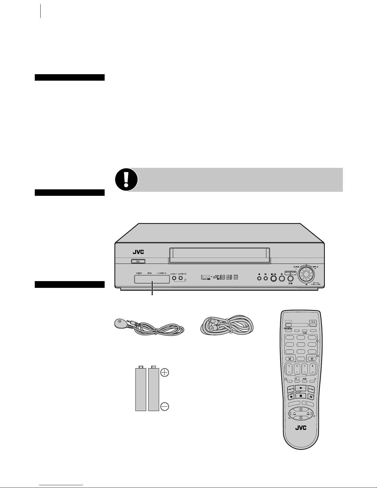
FRONT PANEL
1STANDBY/ON o Button turns
VCR on/off (loading a cassette
also turns power on).
2SATc Button enables/
disables the Auto atellite
Programme Recording mode.
3SATc Ind cator lights up
during Auto atellite Programme
Recording standby mode; blinks
when Auto atellite Programme
Recording is in progress.
4Cassette Load ng Slot is where
cassette is inserted; door closes.
524H EXPRESSc Button
enables 24H Express Timer
Programming.
6Advanced JOG D al enables
picture search, preset position
selection or 24H Express Timer
Programming.
7S-VIDEO Input Connector
enables -VIDEO connection to
camcorder or second VCR.
8VIDEO Input Connector
enables easy connection of video
output from another VCR or
camcorder for editing.
9AUDIO Input Connector [L]
enables easy connection of
audio output (mono) from
another VCR, camcorder or other
source for editing.
10 AUDIO Input Connector [R]
enables easy connection of
audio output (Hi-Fi) from another
VCR, camcorder or other source
for editing.
11 S-VHS ET Button enables/
disables -VH ET mode.
12 S-VHS ET Ind cator lights up
during -VH ET mode.
13 D splay Panel provides clear
view of various displays and
indicators.
14 Infrared Beam Rece v ng
W ndow is where Remote Control
should be aimed when in use. The
maximum operating distance of
the Remote Control is about 8m.
15 T Button starts regular
recording (press once), Instant
Timer Recording (press twice);
sets duration of ITR.
16 | Button stops tape
temporarily during recording;
stops tape temporarily during
playback; plays back frame by
frame with each additional press.
17 § Button stops tape; ejects
tape during top mode.
18 . Button plays back tape;
cancels Pause, till, low, earch
modes.


 User manual")


 User manual")


