Important Safety Precautions
INSTRUCTIONS
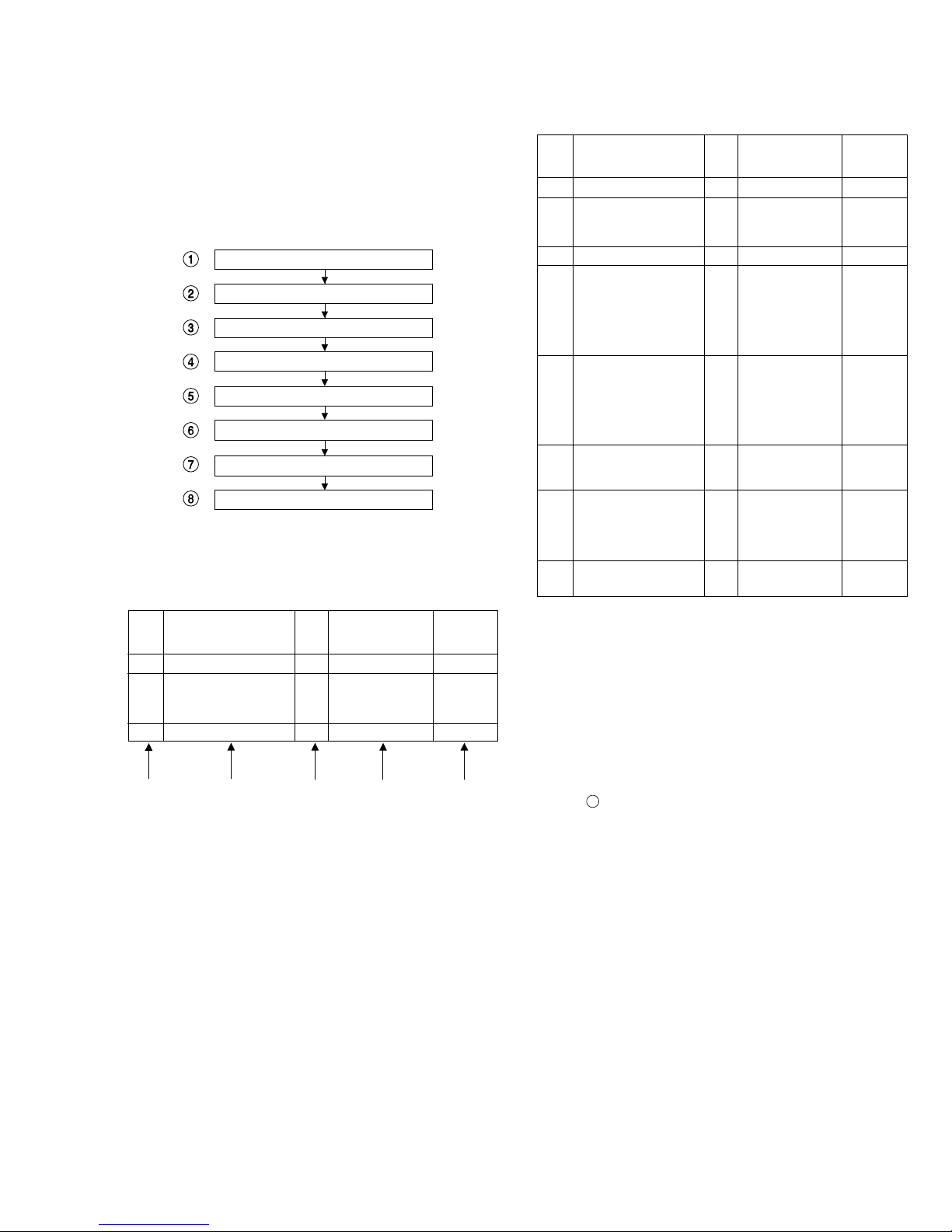
1. DISASSEMBLY
1.1 DISASSEMBLY FLOW CHART ...................................... 1-1
1.2 HOW TO READ THE DISASSEMBLY AND ASSEMBLY 1-1
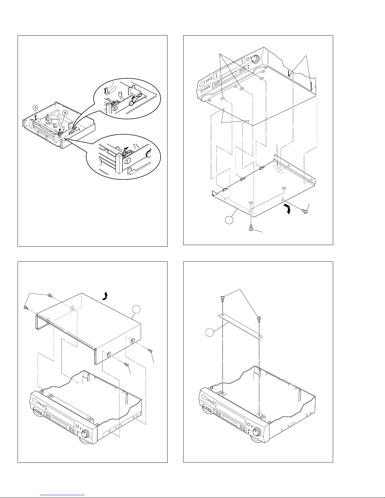
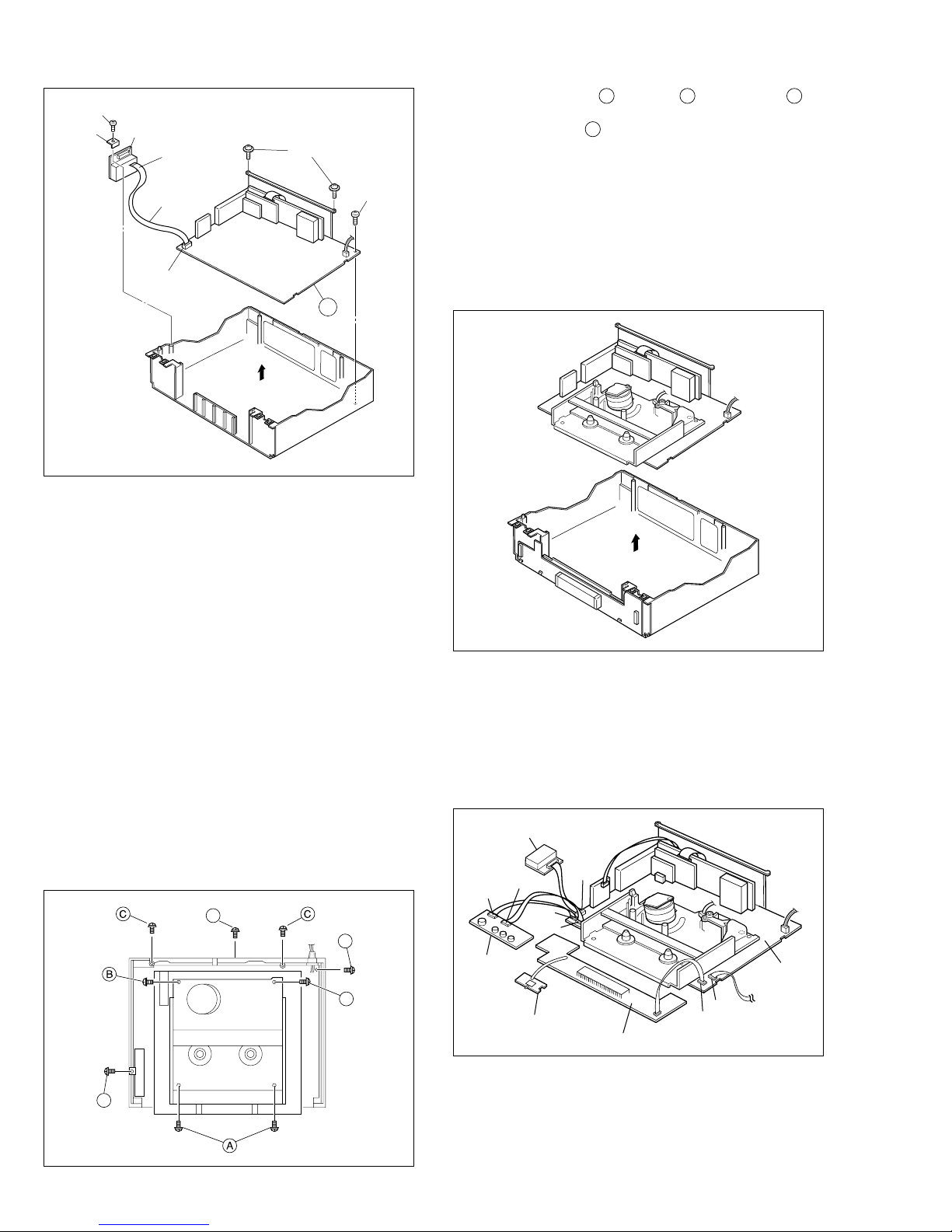
1.3 DISASSEMBLY/ASSEMBLY METHOD .......................... 1-1
1.4 SERVICE POSITION ...................................................... 1-4
1.4.1
How to take out the Mechanism and Main board assemblies
1-4
1.4.2
Precautions for cassette loading in the "SERVICE POSITION"
1-5
1.4.3 Cassette loading and ejection methods in the
“SERVICE POSITION”(See Fig. 1-4-3). .................... 1-5
1.5 MECHANISM SERVICE MODE ..................................... 1-5
1.5.1 How to set the "MECHANISM SERVICE MODE" ..... 1-5
1.6 EMERGENCY DISPLAY FUNCTION ............................. 1-6
1.6.1 Displaying the emergency information ...................... 1-6
1.6.2 Clearing the emergency history ................................. 1-6
1.6.3 Emergency content description ................................. 1-7
1.6.4 Emergency detail information 1................................ 1-8
1.6.5 Emergency detail information 2................................ 1-9
1.7 SYSCON CIRCUIT ....................................................... 1-10
1.7.1 Syscon CPU pin function (IC3001) 1/2 .................... 1-10
1.7.2 Syscon CPU pin function (IC3001) 2/2 .................... 1-11
1.8 SERVICING THE VIDEO NAVIGATION FUNCTION .... 1-12
1.8.1 Copying the video navigation data .......................... 1-12
1.8.2 Erasing the video navigation data (Initialization) ..... 1-13
1.8.3 Factory setting level during shipment ...................... 1-13
2. MECHANISM ADJUSTMENT
2.1 BEFORE STARTING REPAIR AND ADJUSTMENT ........ 2-1
2.1.1 Precautions ............................................................... 2-1
2.1.2 Checking for Proper Mechanical Operations ............. 2-1
2.1.3 Manually Removing the Cassette Tape ..................... 2-1
2.1.4 Jigs and Tools Required for Adjustment .................... 2-2
2.1.5 Maintenance and Inspection ..................................... 2-3
2.2 REPLACEMENT OF MAJOR PARTS ............................ 2-6
2.2.1 Before Starting Disassembling (Phase matching
between mechanical parts) ....................................... 2-6
2.2.2 How to Set the Mechanism Assembling Mode .......... 2-6
2.2.3 Cassette Holder Assembly ........................................ 2-6
2.2.4 Pinch Roller Arm Assembly ....................................... 2-8
2.2.5 Guide Arm Assembly and Press Lever Assembly ..... 2-8
2.2.6 Audio Control Head ................................................... 2-8
2.2.7 Loading Motor ........................................................... 2-8
2.2.8 Capstan Motor ........................................................... 2-9
2.2.9 Pole Base Assembly (supply or take-up side) ........... 2-9
2.2.10 Rotary Encoder ...................................................... 2-10
2.2.11 Clutch Unit ............................................................. 2-10
2.2.12 Change Lever Assembly, Direct Gear, Clutch Gear
and Coupling Gear ................................................ 2-10
2.2.13 Link Lever .............................................................. 2-11
2.2.14 Cassette Gear, Control Cam and Worm Gear ....... 2-11
2.2.15 Control Plate .......................................................... 2-11
2.2.16 Loading Arm Gear (supply or take-up side) and
Loading Arm Gear Shaft ........................................ 2-12
2.2.17
Take-up Lever, Take-up Head and Control Plate Guide
2-13
2.2.18 Capstan Brake Assembly ...................................... 2-13
2.2.19 Sub Brake Assembly (take-up side) ...................... 2-13
2.2.20
Main Brake Assembly (take-up side), Reel Disk (take-up side)
and Main Brake Assembly (supply side) ................................
2-13
2.2.21 Tension Brake Assembly, Reel Disk (supply side)
and Tension Arm Assembly .................................... 2-14
2.2.22 Idler Lever, Idler Arm Assembly ............................. 2-14
2.2.23 Stator Assembly ..................................................... 2-14
2.2.24 Rotor Assembly ..................................................... 2-14
2.2.25 Upper Drum Assembly ........................................... 2-15
2.3 COMPATIBILITY ADJUSTMENT .................................. 2-16
2.3.1 Checking/Adjustment of FM Waveform Linearity .... 2-16
2.3.2 Checking/Adjustment of the Height and Tilt of the
Audio Control Head ................................................. 2-17
2.3.3
Checking/Adjustment of the Audio Control Head Phase
(X-Value) ........................................................................
2-17
2.3.4
Checking/Adjustment of the Standard Tracking Preset .
2-18
2.3.5 Checking/Adjustment of the Tension Pole Position . 2-18
3. ELECTRICAL ADJUSTMENT
3.1 PRECAUTION ................................................................ 3-1
3.1.1 Required test equipments ......................................... 3-1
3.1.2 Required adjustment tools ......................................... 3-1
TABLE OF CONTENTS
Section Title Page Section Title Page
3.1.3 Color (colour) bar signal,Color (colour) bar pattern ... 3-1
3.1.4 Switch settings and standard precautions ................. 3-1
3.1.5 EVR Adjustment ........................................................ 3-1
3.2 SERVO CIRCUIT ............................................................ 3-2
3.2.1 Switching point .......................................................... 3-2
3.2.2 Slow tracking preset .................................................. 3-2
3.2.3 Dynamic Drum preset ................................................ 3-2
3.3 VIDEO CIRCUIT ............................................................. 3-3
3.3.1 D/A level .................................................................... 3-3
3.3.2 EE Y level .................................................................. 3-3
3.3.3 PB Y level (S-VHS / VHS) ......................................... 3-3
3.3.4 REC color (colour) level ............................................ 3-4
3.3.5 Video EQ (Frequency response) ............................... 3-4
3.3.6 AUTO PICTURE initial setting ................................... 3-5
3.4 AUDIO CIRCUIT ............................................................. 3-5
3.4.1 Audio REC FM .......................................................... 3-5
3.5 DEMODULATOR CIRCUIT ............................................. 3-5
3.5.1 Input level .................................................................. 3-5
3.5.2 Stereo VCO ............................................................... 3-5
3.5.3 Stereo filter ................................................................ 3-6
3.5.4 Separation - 1 ............................................................ 3-6
3.5.5 Separation - 2 ............................................................ 3-6
3.5.6 SAP VCO ................................................................... 3-6
4. CHARTS AND DIAGRAMS
NOTES OF SCHEMATIC DIAGRAM .................................... 4-1
CIRCUIT BOARD NOTES ..................................................... 4-2
4.1 BOARD INTERCONNECTIONS ..................................... 4-3
4.2
VIDEO/AUDIO AND AUDIO ERASE SCHEMATIC DIAGRAMS
4-5
4.3 VSC SCHEMATIC DIAGRAM ........................................ 4-7
4.4 SYSTEM CONTROL SCHEMATIC DIAGRAM .............. 4-9
4.5 SWITCHING REGULATOR SCHEMATIC DIAGRAM .. 4-11
4.6 TUNER SCHEMATIC DIAGRAM ................................. 4-13
4.7 CONNECTION SCHEMATIC DIAGRAM ..................... 4-15
4.8 3D DIGITAL/4M SCHEMATIC DIAGRAM .................... 4-17
4.9 TERMINAL SCHEMATIC DIAGRAM ........................... 4-19
4.10 DEMODULATOR SCHEMATIC DIAGRAM ............... 4-21
4.11 S-SUB SCHEMATIC DIAGRAM ................................ 4-23
4.12 NAVIGATION SCHEMATIC DIAGRAM .................... 4-25
4.13 SW/DISPLAY, REC SAFETY, JACK AND JOG
SCHEMATIC DIAGRAMS ......................................... 4-27
4.14 GR SCHEMATIC DIAGRAM ..................................... 4-29
4.15 MAIN, AUDIO ERASE, A/C HEAD AND
LOADING MOTOR CIRCUIT BOARDS .................... 4-33
4.16 3D DIGITAL/4M CIRCUIT BOARD ............................ 4-35
4.17 TERMINAL CIRCUIT BOARD ................................... 4-36
4.18 DEMODULATOR CIRCUIT BOARD ......................... 4-37
4.19 S-SUB CIRCUIT BOARD .......................................... 4-37
4.20 NAVIGATION CIRCUIT BOARD ............................... 4-39
4.21 GR CIRCUIT BOARD ................................................ 4-40
4.22 SW/DISPLAY, REC SAFETY, JACK AND JOG
CIRCUIT BOARDS .................................................... 4-41
4.23
FDP GRID ASSIGNMENT AND ANODE CONNECTION
4-43
4.24 REMOTE CONTROL SCHEMATIC DIAGRAM ......... 4-44
4.25 VOLTAGE CHARTS .................................................. 4-45
4.26 SYSTEM CONTROL BLOCK DIAGRAM .................. 4-49
4.27 VIDEO BLOCK DIAGRAM ........................................ 4-51
4.28 AUDIO BLOCK DIAGRAM ........................................ 4-55
5. PARTS LIST
5.1 PACKING AND ACCESSORY ASSEMBLY <M1> ......... 5-1
5.2 CABINET AND CHASSIS ASSEMBLY <M2> ................ 5-2
5.3 MECHANISM ASSEMBLY <M4> ................................... 5-4
5.4 ELECTRICAL PARTS LIST ............................................. 5-6
MAIN BOARD ASSEMBLY <03> ......................................... 5-6
3D DIGITAL/4M BOARD ASSEMBLY <05> ...................... 5-12
TERMINAL BOARD ASSEMBLY <06> .............................. 5-13
AUDIO CONTROL HEAD BOARD ASSEMBLY <12> ....... 5-14
DEMOD BOARD ASSEMBLY <14> .................................. 5-14
S-SUB BOARD ASSEMBLY <15> ..................................... 5-15
NAVIGATION BOARD ASSEMBLY <19> .......................... 5-15
DISPLAY BOARD ASSEMBLY <28> ................................. 5-16
REC SAFETY BOARD ASSEMBLY <32> ......................... 5-17
S JACK BOARD ASSEMBLY <36> ................................... 5-17
JOG BOARD ASSEMBLY <37> ........................................ 5-17
AUDIO ERASE BOARD ASSEMBLY <46> ....................... 5-17
LOADING MOTOR BOARD ASSEMBLY <55> ................. 5-17
GR BOARD ASSEMBLY <96> .......................................... 5-17