K-array KA10 User manual

www.k-array.com
REV. A ENGLISH
KA line KA10


CONTENTS
m
m
m
m
m
m
m
m
m
m
m
s
s
1. Introduction p. 5
4. Warranty
6. Features p. 7
7. Included accessories p. 8
8. Wiring p. 8
9. Required voltage p. 8
10.Front panel p. 9
11. p. 9
12.DSP control and remote control p. 10
2. Unpacking p. 5
3. Symbols p. 6
p. 6
5. Safety p. 7
Rear panel
13.Remte control software p. 11
14.Specification p. 15
15.Included rack adapters p. 16
16.Service p. 17
m
s
s
3


Congratulations on your purchase of the K-Array KA10.
The KA professional rack amplifier line has been designed to give answers to all the needs of touring and
installation applications in which a large amount of power is needed together with the maximum flexibility,
over low sizes and weight. The sophisticate electronics on-board allow to reach outstanding output power
levels with over-high efficiency. DSP on-board can provide perfect signal processing for all K-array products,
providing safe working conditions and a large choice of dedicated presets to solve the most parts of the needs
of high-end applications. A dedicated remote control ensures a constant connection with all the units, allows
the total management of the presets installed and the possibility of the download of new ones.
Each K-array device is built to the highest standard and thoroughly inspected before leaving the factory.
Carefully inspect the shipping carton before opening it, and then examine and test your new loudspeaker. If
you find any damage immediately notify the shipping company. Only the consignee may institute a claim for
damages incurred in shipping. It is suggested that you retain the original packaging so that the amplifier can
be repacked at a future date if necessary.
Please note that K-array and its distributors cannot accept any responsibility for damage to any returned
product through the use of non-approved packaging.
2. UNPACKING
1. INTRODUCTION
KA line KA10
5

P. 2
3. SYMBOLS
!
This symbol, wherever it appears, alerts
yo u to i mp or tan t op er ati ng a nd
m a i n t e n a n c e i s t r u c t i o n s i n t h e
accompanying literature. Read the
manual!
Separate collection of electrical and
electronic devices.
For information about the disposal of
Wa s t e E l e c t r i c a l a n d E l e c t r o n i c
Equipment (WEEE), please refer to the
website at
www.scanning.datalogic.com
This symbol alerts the user
t o t h e p r e s e n c e o f
recommendations about
p r o d u c t ' s u s e a n d
maintenance.
W a r n i n g ! D a n g e r o u s
voltages: RISK .
This device complies with
Restriction of Hazardous
Substances Directive.
The item meets all the
e s s e n t i a l " H e a l t h a n d
Safety" requirements of the
r e v e l a n t E u r o p e a n
Directives.
4. WARRANTY
K-array KA 10 are warranted against manufacturing defects in materials or craftsmanship over a period of
from the date of original purchase. During the warranty period K-array will, at it's discretion, either repair
or replace products which prove to be defective provided that the product is returned in its original packaging,
shipping prepaid, to an authorised K-array service agent or distributor. K-array cannot be held responsible for
defects caused by unauthorised modifications, improper use, negligence, exposure to inclement weather
conditions, act of God or accident, or any use of this product that is not in accordance with the instructions
provided by K-array.
K-array is not liable for consequential damages.
This warranty is exclusive and no other warranty is expressed or implied.
This warranty does not affect your statutory rights.
2
years
Contact your dealer or distributor for repair or replacement.
6

WARNING !
!
• To reduce the risk of electric shock, disconnect the amplifier from the AC mains before installing audio
cable. Reconnect the power cord only after making all signal connections.
• Connect the amplifier to a two-pole, three wire grounding mains receptacle. The receptacle must be
connected to a fuse or circuit breaker. Connection to any other type of receptacle poses a shock hazard
and may violate local electrical codes.
• Do not install the amplifier in wet or humid locations without using weather protection.
• Do not allow water or any foreign object to get inside the amplifier. Do not put objects containing liquid
on, or near, the unit.
• To reduce the risk of overheating the amplifier, avoid exposing it to direct sunlight. Do not install the
unit near heat emitting appliances, such as a room heater or stove.
• No naked flame sources such like lighted candles should be placed on the device.
• The amplifier should be placed so that its location does not interfere with its proper ventilation. For
example, the appliance should not be situated on a bed, carpet, or similar surface that may create an
obstacle for the ventilation openings.
• CAUTION, RISK OF ELECTRIC SHOCK, DO NOT OPEN. This amplifier contains potentially
hazardous voltages. Do not attempt to disassemble the unit. The unit contains no user serviceable
parts. Repairs should be performed only by factory trained service personnel.
• Be sure that both voltage set by the selector on the device andAC Power have the same value.
5. SAFETY
!
!
!
!
!
!
!
!
!
Over-light weight
Compact design, 2U rack for 4 chs
Optical limiters
Electronically protected
Over-high efficiency
DSP on-board to drive all K-array products
Remote control and dedicated management software
Top quality components for outstandig performances
Aluminium frame
6. FEATURES
7

- 2 Rack adapters
- 2 xlr Neutrik cable mt. 0,5
- 1 Lan cable, 8 poles cat5
- 1 adjustment pen screwdriver
- 1 software and utilities CD
- 1 User's manual
KA 10 operates safely and without audio discontinuity if the AC voltage stays within either of two operating
windows: 95-125 (voltage selector on 115 V) or 195-250 V (voltage selector on 230 V), at 50 or 60 Hz.
115-230
The device is default set to be connected to 230 V AC Power. To use the device on a 115 V AC Power you
need, before connecting it, to move , just loosening the two screws, and to choose
the correct use voltage by the red switch. Be sure that both voltage set on the selector and AC Power have the
same value . Always close the voltage selector's cover before connecting the device to AC Power. Change
the label that points out the correct voltage in use.
the voltage selector's cover
CH1 OUT CH2 OUT
CH2 +CH1 +
CH2 +
CH2 -CH1 -CH2 -
2+2+
1+1+
2-2- 1-1-
Speakon connector Speakon connector
CH1 in
CH1
hot
3
21
XLR connector
CH1
grd
CH1
cold
CH1
hot
3
12
CH1
grd
CH1
cold
CH1 out CH2 in
CH2
hot
3
21
XLR connector
CH2
grd
CH2
cold
CH2
hot
3
12
CH2
grd
CH2
cold
CH2 out
Connecting a 115V system on a 230V AC Power causes heavy
damages to the device and serious risk for users .
CAUTION
! !
7. INCLUDED ACCESSORIES 8. WIRING
9. REQUIRED VOLTAGE
8

10. FRONT PANEL
11. REAR PANEL
9 cm
20 cm
44,5 cm
Address selector
(rotary x10 - x1)
Display
(ID number -
Preset loaded)
Power switch
Powercon IN
Powercon OUT
max 17A
CH2 Speakon OUT
(1+ 1-)
RS485 Remote control
(Parallel)
Input level PAD
Ground lift switch
CH1 XLR balanced
parallel connectors
CH2 XLR balanced
parallel connectors
CH1 Speakon OUT
(1+ 1-)
CH2 Speakon OUT
(2+ 2-)
Preset selector
(push one to change,
keep 10 sec to store)
Dual / Link switch
(Dual mode Stereo
independent channels /
Link CH1 & CH2 for Bridge Use*)
*The link mode is designed for Bridge applications,
the output signal of CH1 & CH2 is out of phase!
9

A powerful DSP manages all the
functions of the speakers. Each
system can store on board 16
preset that can be recalled pushing
the PRESET button. Once the
preset will appear on the lower line
of the display it will become
automatically available after few
seconds. If you desire to set a
preset as “default”you just need,
once selected it, to keep pressed
for five seconds the PRESET
button. After that, this preset will
automatically be recall each time
you will switch on your module. It is
also possible to remote each
module by an RS485 serial port. In
11.1 Cloner function & preset systems
It is possible to clone the entire presets bank from Speaker to Speaker without any PC
connected. We will call SpeakerA the one with the presets bank that you want clone, and
SpeakerB the one that will be upgraded.
Set the SpeakerA on ID 99, will appear CLONER on the display
Keep SpeakerB on any ID number between 10 and 90.
Turn off both the speakers and connect by a RJ45 8 poles cable
Turn on the SpeakerB and after the SpeakerA
SpeakerA will start to clone, on the display will appear a cont down (00/15, 01/15, etc)
Wait till 20 seconds after 15/15
Change the ID of the SpeakerA to any other ID and turn off both Speakers
Turning on the SpeakerA check that it is on mode 16x16 and NOT 4x4.
If SpeakerA is in mode 4x4, just turn off the speaker and keep press the Preset button during
the turning on
The preset are cloned to the SpeakerB.
12. DSP CONTROL AND REMOTE CONTROL
order to remote your system, you need to set each module on a different address, so that, in your chain, no one module will
have the same address. Two rotary encoders allow you to set the desired address number that will appear on the top line of
the display. Using the remote control software it is possible to mute each system, select a desired preset loaded on-board or
download a new preset pack.
For remote control operation please refer to REMOTE CONTROLAND SOFTWARE MANUAL in the next pages.
10
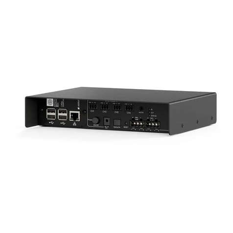
1 . To connect the K-array modules to a PC, it is needed a RS485-USB adapter, we recommend the K-USB
adapter (pic.1).
2 . Install the K array control software from installer in the CD-ROM
2.1 Start the Karray_manager_V2 from Windows - Start - Software - Karray_manager_V2
2.2 Click on NO when ask for demo mode start
2.3 Click on System - Settings to configure which COM port use, the COM port of K-USB, usually is
the higher number. If you don't find, you can check it on windows-control panel-system-hardware-COM Port
Connect the K-usb to a PC and install the drivers required
included in the CD-ROM.
K-USB
USB to RS485 adapter
1
Operating systems:
Minimum requirements:
Recommended requirements:
Win98/98SE/Me/2000/XP/Vista
CPU 300 MHz
RAM 128 Mb
RAM 512 Mb
SYSTEM REQUIREMENTS
13. REMOTE CONTROL SOFTWARE
11

3 . ID setting
4 . Single module control
Pressing this button you can have a
refresh of the modules connected.
Click once on the ID module
that you want control.
Pr e se t s lo t s on t h e
M o d u l e s t a t u s
On this bars you can see all the
modules connected in your net.
FROM PC
ADDRESS
PRESET IN USE
PRESET SELECTOR
ID 39
KZ+KS
ID X 10
ID X 1
TO NEXT MODULE
Temperature rectangle red
Temperature rectangle green
Protection/Fail rectangle red
Temperature rectangle green
: one module
inside that loudspeaker is over-temperature.
: all modules
inside that loudspeaker have a good
temperature.
: at least one
module inside that loudspeaker is in
protection.
: all modules
inside that loudspeaker are working properly.
Temperature rectangle black: if this rectangle
is black it means that the loudspeaker is not
responding.
The main causes of this malfunction are loss
of power supply and loss of serial connection
between the hub and the loudspeaker. Check
the hardware. If this rectangle is black will be
black also the Protection/Fail.
Protection/Fail rectangle black: see above.
The remaining rectangle: Is related to the
mute function; if red, the related loudspeaker
is in "mute" status.
This frame describes the state of all the loudspeakers on the net. The colour of the little rectangles into this
frame represents the status of the loudspeakers. Each loudspeaker has three rectangles. Here there is the
meaning of the rectangle's colour.
Two rectangles on top:
: the loudspeaker is not present on the net.Both rectangles grey
12

Preset names
Select the preset number, write
the name, maximum 5 characters,
press the Send button
With this button, you can load
presets from PC to the module,
you have to press, choose the slot
that you want use and select the
.EQS file that you want to load.
Module details
Mute Module
Store the active preset to
default when restart the
module
Module status panel
5. Mute groups
On the Mute Groups window, you can manage the modules Mute as groups, up to 4 different.
5.1 Choose the modules from the list on the right
Press the right arrow of the group that you prefer, to add the modules
5.2 It is possible to assign names to the groups, just writing in the fields.
13

6. Preset groups
7. Text editor
It is available a text editor on the software, it can manages .RTF files.
6.2 It is possible to assign
On the Preset Groups window, you can manage the modules Presets as groups, up to 4 different.
6.1 Choose the modules from
the list on the right.
Press the right arrow of the
group that you prefer, to
add the modules.
Select the number of the
preset you want to choose,
names to the groups, just
writing in the fields.
8. Master Mute control
It is possible to Mute all the modules connected just pressing Master Mute button.
To protect from accidental pressing of this button, you will need to Unlock by pressing the Unlock
button below it.
9. Exit option
When you choose to exit from the software, will appear an alert window that alert you about
10. Save and Load
It is possible to save the speakers configuration for Mute and Preset Groups, just Save a .CONF file.
Unmuting all the modules connected, this is important because the Mute function is controlled only
It is possible to use XLR
adapters for connections,
h e r e b e l o w , t h e
connection schematic.
1 2 3 4 5 6 7 8
brown
white
orange
green
1
1
2
2
3
2
1
14

Output power
Continuous 4 (0.5% THD)
EIA 4 (1% THD)
Continuous 8 (0.5% THD)
EIA 8 (1% THD)
Bridged - EIA 8 (1% THD)
Audio Specs
Slew Rate 8
S/N Ratio
Distortion
Input impedance
Gain
Output
Bandwidth
Damping Factor 8 (100 Hz)
Protections
Thermal protection
Short circuit / over-load
Clip Limiter, Perm. signal li miter
Audio Input
Connectors
Wiring
Remote control Input
Connectors
Power Output
Connectors
Power Input / Output
Connectors
AC power
Operating range
I. nom
Max continuos and burst current
Physical
Measures
Weight
J
J
J
W
W
W
W
W
W
W
390 W1
2
1
2
2
500 W
240 W
260 W
1000 W
50V/uS
>105 dB/A
<0.5 (THD, DIM, SMPTE)
20K bal. 10K unbal.
Variable
Unbalanced to ground
10 Hz - 30 KHz
>500
Yes
Yes
Yes
2 x male + 2 x female 3 poles balanced XLR
= ground / Pin = hot / Pin =
cold
2 x female 8 poles RJ45
2 x female Speakon 4 poles
2 x PowerCon Parallel IN/OUT (max out 17A)
230 V 5A(>10s) - 10A (<1s)
115 V 10A(>10s) - 20A(<1s)
88(2U)x200(½Rack) x485mm
3.5 Kg
Pin1 2 3
115/230 V 50 / 60 Hz
2.6 - 1.6 A
Notes for data
1. RMS Continuous Power, both channel driven on nominal load
2. RMS Power tested under the specifications of EIAJ standard, both channel driven on nominal load.
14. SPECIFICATIONS
15

DOUBLE RACK
SINGLE RACK
Unscrew the 4 anchor points of the
front panels and remove it.
Fix by the supplied screws the two
rack adapters as shown in the
drawing.
Remove the smaller steel spacer (S2)
from DEVICE A and traslate S1 on
DEVICE B like in the draw beside.
Then refit the front panels fixing all the
4 screws on DEVICE B and just the
two ones through S1 on the DEVICEA
Plug the two devices together
by the last two screws and fix
the rack adapters.
spacers
S1 S2
S1
S2
STEP 1
STEP 2
STEP 3
15. INCLUTED RACK ADAPTERS
16

16. SERVICE
To obtain service:
Any attempt to modify or replace components of the device will invalidate your warranty. Service must
be performed by an authorized K-array service center.
1) Contact the official K-array distributor in your country that direct you to the service centre.
2) If you are calling for the service, have the serial number(s) of the unit(s) at hand for reference. Ask for
Customer Service, and be prepared to describe the problem clearly and completely.
3) If the problem cannot be resolved over the phone, you must return the unit for service.
4) You will be given an RA (Return Authorization) number for job tracking. Refer to this number on shipping
materials and in all correspondence concerning the repair. Shipping charges are the responsibility of the
purchaser.
Cleaning:
•Clean the product enclosures using only a soft, dry cloth.
•Do not use any solvents, chemicals, or cleaning solutions containing alcohol, ammonia, or abrasives.
•Do not use any sprays near the product or allow liquids to spill into any openings.
17

KZ10
KT
KT+KS
KV KZ+KS
K5+KS L2+K5
CH.2 CH.1
CH.2 CH.1
KV+KS
CH.2 CH.1
CH.2 CH.1 CH.1 CH.2
KZ10 flat EQ KT20 flat EQ
CH1.KZ10 flat EQ - .KKS50 flat EQCH2KV50 flat EQ
CH1.KT10 flat EQ - .KKS50 flat EQCH2 CH1.KV10 flat EQ - .KKS50 flat E QCH2
CH1.KL12 flat EQ - .KK50 flat EQCH2
CH1.KK50 flat EQ - .KKS50 flat EQCH2
17. PRESETS LIST - RELEASE - B
18

KK50 KK100
KVsolo
KTsolo
KK200 KKS50
K5solo KM81F
KK50 flat EQ KK100 flat EQ
KKS50 flat EQ
KK200 flat EQ
KT20 extended EQ KV50 extended EQ
KK50 extended EQ KM8 single
19

Table of contents
Other K-array Amplifier manuals

K-array
K-array KA14 User manual

K-array
K-array Kommander-KA02 User manual

K-array
K-array Azimut Series User manual

K-array
K-array KA7 User manual

K-array
K-array KA40 User manual

K-array
K-array KA24 User manual

K-array
K-array Kommander-KA04 User manual

K-array
K-array Kommander-KA Series User manual

K-array
K-array Kommander-KA02 User manual

K-array
K-array KA10-10 User manual