KTI75146 A 7 rev. 04/04/17
INSTRUCCIONES DE ENSAMBLE 5.
6.
7.
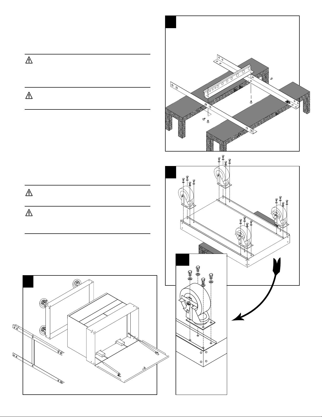
Paso 5: Sujetando la charola inferior y el
ensamble del cajón a la patas
Alinee los agujeros en las patas con los agujeros
equivalentes en la charola inferior y el ensamble
de cajón, según se ilustra en la figura 5. Inserte los
pernos por las patas y en la charola inferior y/o el
ensamble de cajón y sujete desde el interior con los
pernos tipo estrella para pata hasta que se hayan
sujetado y apretado manualmente todos los agujeros
laterales.
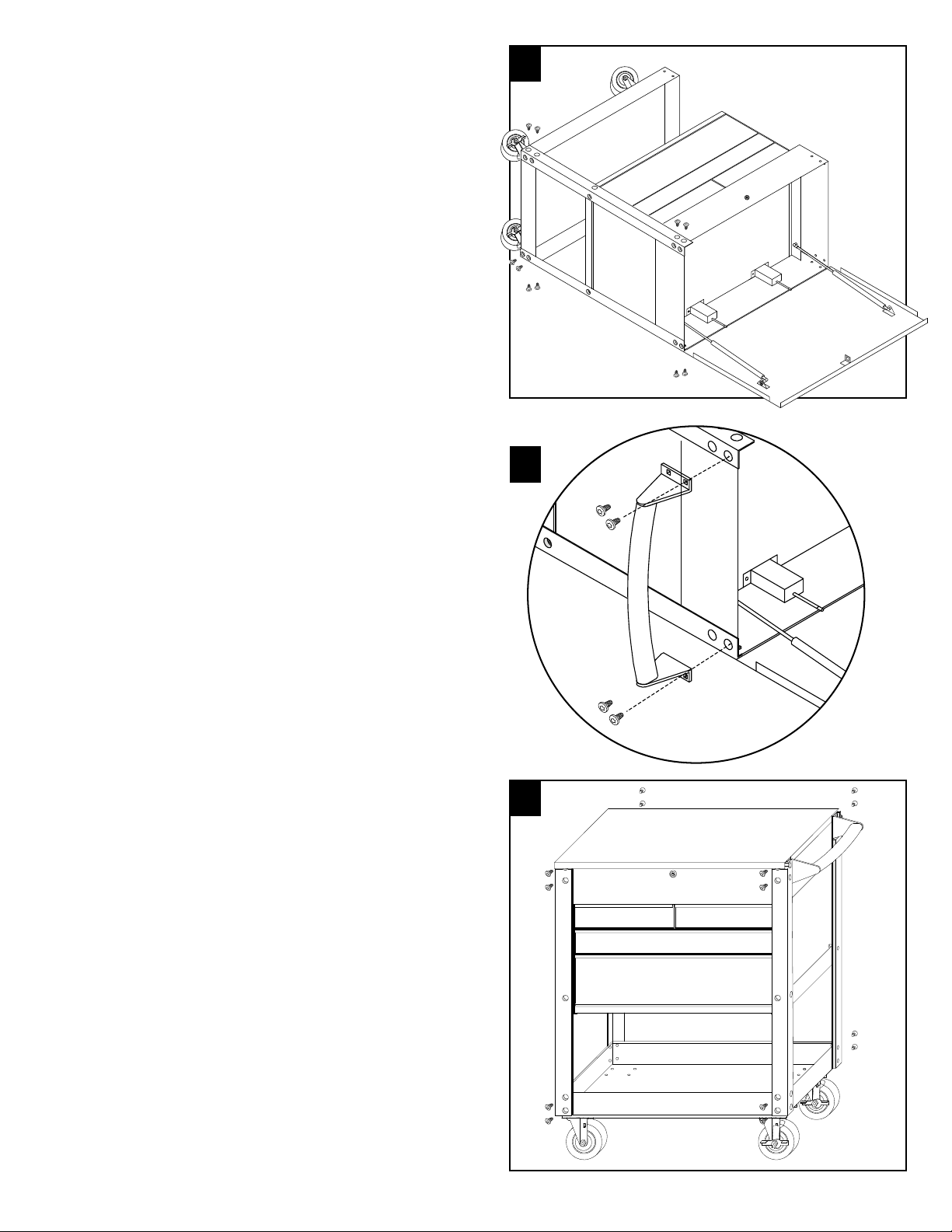
Paso 6: Sujetando la manija
(A) Alinee las demás patas con las equinas delanteras
de la charola inferior y el ensamble de cajón. Alinee
el agujero en la manija con el segundo agujero en
el ensamble de cajón y pata (no sujetada) según se
ilustra en la figura 6. Inserte los pernos de manija M8
x 19 por la manija, por las patas y por el ensamble de
cajón, según se ilustra en la figurea 6. Sujete de con
los pernos tipo estrella con el equipo de los pernos de
mango y apriete manualmente..
(B) Sujete los pernos M8 x 17 restantes (en el lado
opuesto de la manija de empuje) directamente en las
patas.
Paso 7: Sujetando las patas
Usando dos personas, voltee el carrito hacia su
posición vertical. Siga sujetando con los pernos por
los agujeros alineados en la parte delantera y posterior
del carrito con los pernos M8 x 17, y los pernos tipo
estrella, según se ilustra en la figura 7. Apriételos
manualmente. TODOS los agujeros deberán ahora
estar alineados y sujetados.
Paso 8: Apretando los pernos (no ilustrado)
Use un destornillador T40 para apretar todos los
pernos. Asegúrese de aplicar una presión al cabezal
del perno al momento de apretarlo, con el fin de
mantenerlo en la posición correcta. Una vez que se
hayan apretado todos los pernos, su carrito está
completo. Consulte la página 4 por el desglose de
partes.