K1EL K45 User manual

34 December 2022 QST www.arrl.org
Product Review
Bottom Line
The K1EL K45 CW modem has a large set of
capabilities and is adaptable to just about
every sort of CW operation.
Pascal Villeneuve, VA2PV
,
Reviewed by Paul Danzer, N1II
n1ii@arrl.net
This lightweight (12 ounces), compact (4.25 × 3.25 × 2.1
inches) unit is known as “the Swiss Army knife of CW
keyers.” Its predecessor, the K1EL K16 (reviewed in the
February 2017 issue of QST), had a set of 39 com-
mands, in addition to message storage and processing,
numbering, and any function you might want in a keyer.
However, in addition to four pushbuttons, it was Morse
in, Morse out. The K45 adds a USB port for a keyboard,
a four-line-by-20-character display with status indicators,
an audio input jack for a CW reader, beacon capability,
and several other features.
For manual CW it retains the K16 CW command lan-
guage, but when a keyboard (not included in the
package) is plugged in, there are several pages of allow-
able commands. Some of the functions may come as a
surprise; for example, there is the capability to lock the
transmit speed to the receive speed. There is a 44-page
online manual that includes detailed interface instruc-
tions. A summary of interface cable connections is also
available, and it is best to read the “Quick Start”
(Appendix B) information in the instruction manual and
then the one-page supplement. One capability I found
useful — which is often missing from other keying units
— is pressing
CTRL T
to toggle transmit on and off. This
is helpful for checking power out, SWR, and the like
when using paddles rather than a straight key. Addition-
ally, built in is a Morse tutor, with functions like the K1EL
Morse Tutor (reviewed in the May 2020 issue of QST).
Please note that the K45 has a WinKeyer mode that
allows it to work the same as the K1EL WinKeyer USB
product, so both products are included in one box.
The CTRL and ESC Keys Are Important
The commands for setting up and controlling the K45
are selected by using two keys:
CTRL
(control) and
ESC
(escape). Control commands are immediate. As soon as
you press the
CTRL
key and a selected letter, the
resulting command takes effect. For example,
CTRL T
K1EL K45
CW Modem
Figure 2 — One of the ve menu screens brought up by ESC+C.
Figure 1 — Partial list of CTRL commands. The up/down arrows
on the keyboard or the front panel rotary control will move to the
rest of the list.
toggles the key down (tunes) on and off;
CTRL B
sends
73 de (your call stored in F11); and
CTRL R
sends 5NN.
There are approximately 15 such commands.
CTRL H
brings up a list of these commands (see Figure 1). You
can scroll through the list vertically by using the key-
board up and down arrows.
The
ESC
key controls various options and settings
through a set of menus. To call up the menus, press
ESC
followed by
C
. The top-level menu contains ve
parts, one of which is shown in Figure 2. Each part has
eight selections. See the sidebar, “Using the
ESC
Key,”
at www.arrl.org/qst-in-depth for more details.

www.arrl.org QST December 2022 35
Figure 3 — Back panel connections. The three leftmost jacks
accept 1⁄8-inch stereo plugs. A cable matching the USB host con-
nector to a USB jack is supplied with the unit. A standard USB
keyboard plugs into the right-hand socket.
modes (not CW) you may need to install a driver in your
PC. Detailed instructions in the manual describe how to
go about it. I have a 2014 HP desktop computer; I just
plugged in the USB cable (supplied with the K45) and all
was well. I also tried an inexpensive 120 V ac-to-USB
plug converter, and again the unit ran well.
Keyboard
Most USB keyboards will work. I tried a wired USB unit
and a wireless unit; both worked with no problem —
just as the K45 manual said they would. A USB Type-A
connector for a keyboard is located on the rear of the
enclosure.
Messages and Macros
A set of 12 messages, each 120 characters long, can be
stored (see the sidebar, “Storing and Editing a Mes-
sage,” at www.arrl.org/qst-in-depth for more details).
Having a keyboard makes it easy to write a message,
store it, and edit it. Two sets of messages can be stored.
The unit allows setting up two users, and you can toggle
between the two every time you press
CTRL U
. When
the user is changed, a brief message ashes on the
status line while the current conguration is changed.
Each user has customized settings and a message list.
I set up a group of messages for everyday operating,
including brief exchange messages for working “hit and
run” DX contacts.
I stored (and changed) messages as user 2 with the
requirements of a contest. Serial number insertion,
chaining message, and repeating are also set with key-
board commands.
Beacon operation is supported with the ability to set
spacing, delays, speeds, and repetition rates.
Key mapping is also available. A set of 20 preset
remapped characters is included; each can be
remapped to another key.
CW Speeds
Transmit keying range is specied as 5 – 99 words per
minute, and rounding it off for ve-letter groups (ve let-
ters plus one space per word) translates to approxi-
mately 600 letters per minute maximum. But before you
think using a keyboard will turn you into a very high-
speed transmit operator, consider that most average
skilled people type 190 – 200 letters per minute or
38 – 40 words per minute. Hunt-and-peck typists,
remember — you will not be able to transmit any faster
than you can type!
The instruction book species the CW reader as DSP-
based and operating over the range of 7 – 60 WPM. My
There is only one external control — a rotary encoder
with an integral push switch on the front panel that is
used in congurations and modes where the keyboard
is not used or where it replaces the up/down arrows. All
connections are on the back panel (see Figure 3), with
setup instructions in the manual. For the most part, each
of the connections shown requires only a few words of
explanation. A speaker with adjustable tone and volume
is included in the package.
Iambic Paddle
This can be set as a paddle with or without reverse dot/
dash conguration or a straight key.
Audio Input
This is the only input that requires some thought. You
can connect it to any audio output, such as a speaker,
from your rig. However, you will be controlling both what
you hear and what the CW reader is operating on. The
recommendation is that you connect this input to the
audio line output found on most newer rigs. The manual
for my Icom IC-7300 contains a drawing of the connec-
tions to the accessory socket on the rear. This is a con-
stant level audio output. The K45 has controls to adjust
this level to vary the input for best operation.
Keying Output
This can be congured to provide two independent key
outputs (to use with two rigs, perhaps) without making
any changes. It can also be set for one key output and
the other contact for a push-to-talk (PTT) line, if needed.
The key output is isolated from the K45 metal case. The
output connection is given as a solid-state relay, capable
of handling +/– 350 V at 120 mA.
Host
A Mini Type-A USB connector on the rear is used, for
most modes, as the power source for the unit. For some

36 December 2022 QST www.arrl.org
experience with the K45 was positive; my QTH is about
50 miles from W1AW. Therefore, on 80 meters and
sometimes 10 meters, W1AW was solid and error-free,
as though I was in the W1AW shack in Newington,
Connecticut.
However, as expected, under poor conditions and high
noise, the reader put out some random letters. Often the
rst letter of a string of letters is incorrect, as any CW
reader will not be synchronized to the incoming dots and
dashes.
One operator I copied had what used to be called a
“Missouri Swing,” and to my surprise the CW reader did
very well — better than I could, certainly. What is dif-
ferent from some other CW readers is the instantaneous
control you have. The
CTRL
and
ALT
keys are used to
make changes as you listen and copy:
CTRL
left and right arrows — audio gain adjustment. I
set my rig’s audio output to 80% and trimmed the audio
level using these K45 controls.
ALT
left and right arrows — CW noise lter levels. These
controls cycle through 10 levels of noise ltering.
CTRL
up and down arrows — CW threshold adjustment.
Raise in a noisy environment, and lower when things are
quiet. It is used to reduce false letter triggering when
noisy.
ALT
up and down arrows — CW spacing adjustment.
This is used to change, through 10 selectable values,
the spacing between letters to compensate for incorrect
spacing of incoming letters.
If the incoming letters are machine-sent with the stan-
dard dot-to-dash-to-spacing ratios, this adjustment
shouldn’t be necessary. According to Wikipedia, a dash
is three times the length of a dit; each letter is followed
by a dit length of space, the letters are separated by the
length of three dits, and words are separated by seven
dits. If the ratios are not standard, this is one you must
try for yourself!
LCD Display
The front panel display is four lines by 20 characters.
Backlight level and contrast are adjustable by key press.
You can select what kind of information you see. The top
line is a status readout, with the leftmost number the
decoded CW speed and the rightmost number your
transmit speed. In the center of this line is an S-meter
bar with the selected user number to its right. There are
three more status indicator letters to the right of the user
number. Below the status line, the received letters — or
when transmitting, your transmit letters — are displayed.
Switching between these two can be automatically or
manually controlled.
Both the contrast and the backlight brightness can be
changed. Selecting the fth menu group, followed by
1 for the backlight or 2 for the contrast, allows these set-
tings to be changed (Figure 4). Number selections are
changed with the arrow keys or the knob on the front
panel. The change is conrmed by pressing the
ENTER
key, and a message appears conrming the change.
Additional Modes
HSCW
This mode is used mostly for working stations via
meteor scatter propagation. Short bursts of characters
are sent repetitively at high speeds for a predetermined
period. The receiving station listens and records the
intermittently received bursts and plays them back at a
slow speed to decipher the Morse message.
The K45 instruction manual provides the needed expla-
nation for setting the speed to match the commonly
used rates in the US and Europe.
For more information about HSCW, see https://www.
nitehawk.com/rasmit/ws1_15.html.
QRSS
QRSS uses tiny amounts of power to send messages
long distances. Detailed descriptions on the web point
out that this technique averages seconds of audio,
which correlates in the processing (as compared to the
same time and amount of noise, which does not corre-
late). For example, 200 mW QRSS transmitters are often
spotted on QRSS grabbers thousands of miles away.
The applicable K45 commands for QRSS include set-
ting the speed:
1 = QRSS3: 3-second dits
2 = QRSS6: 6-second dits
3 = QRSS30: 30-second dits
4 = QRSS60: 60-second dits
Figure 4 — Selecting the backlight control screen allows
adjusting this value with the up/down arrow keys or the front
panel rotary control.

www.arrl.org QST December 2022 37
while transmitter key output is assigned to the tip. These
can be changed by command.
In Summary
There is a large set of capabilities in the K45 that you
can select, modify, use, or not use. It is adaptable to just
about every sort of CW operation because it does not
need a PC. Generally, any sort of USB supply will power
it to full ability.
During this test, the unit added quite a bit of interest and
fun to my CW operating. It was interesting to see the let-
ters and words appear on the LCD screen as I com-
pared them with the ones I copied in my head. I am not
a very good typist; when I got tired of using the key-
board, I moved my right hand over to my Bencher pad-
dles and I was back in familiar territory. Brief stored
messages were nothing new here, but the mapped letter
capability was a nice feature.
Manufacturer: K1EL Systems LLC, made in the USA.
https://hamcrafters2.com. Price: $239.
For example, \Q1 selects QRSS3 or 3-second dits, and
\Q4 selects 60-second dits.
Although it’s possible to send QRSS directly from the
keyboard by entering a command before a string, the
most efficient use of QRSS is to format a specic QRSS
message.
RTTY
The K45 can be congured to operate in RTTY transmit
mode. Receive RTTY is not included. The format is
xed to Baudot FSK with many options. Two menus of
choices are provided by a keyboard command (
ESC-R
).
Message storage and editing are also used, as with
straight CW. Most common RTTY functions — reverse,
diddling, and CR/LF handling — can be selected.
The K45 provides FSK output, which directly drives a
transceiver’s FSK input — assuming the transceiver has
this capability. When RTTY is rst enabled, transmitter
FSK output is assigned to the ring of the output jack,
Buddipole BuddiHEX Portable Hexagonal
Beam Antenna
Bottom Line
The BuddiHEX bundle is a complete and
easily transportable antenna system that pro-
vided me the opportunity to make better con-
tacts, farther, and with less noise.
Reviewed by John Leonardelli, VE3IPS
ve3ips@gmail.com
When I was a teenager, I made my rst DX contact from
a local schoolyard using a Citizens Band (CB) walkie-
talkie. It was then that my fascination with ham radio
started. Once I obtained my amateur radio license, I got
much satisfaction from operating from parks or out in the
eld using battery power and portable antennas to rec-
reate the thrill of my rst DX contact. Over the years,
my Buddipole and Buddistick antennas served me well,
but it became time to add a Yagi antenna to my deploy-
ment kit.
My rst thought was to use a three-element Yagi, but the
weight and the inability to transport it in an easy manner
had me looking at alternate antennas. Also, the Yagi
would cover only three bands, and I wanted a solution

38 December 2022 QST www.arrl.org
for 17 and 6 meters. It was around this time that Chris
Drummond, W6HFP, started talking about the Bud-
diHEX antenna and had several prototypes being eld-
tested. I knew instantly that I needed to get one to use in
my portable operations.
Description
The BuddiHEX antenna offers a
W
-shaped driven
element with a
U
-shaped parasitic reector in a two-
element format. This is like some other hexagonal (HEX)
beam antenna designs. Research shows that these
Figure 5 — Vertical feed point (VFP) hub.
Figure 6 — BuddiHEX unboxed.
Figure 7 — Mastwerks mast unboxed.
antennas offer approximately 8 dB forward gain at
30-feet elevation and approximately 15 – 20 dB front-to-
back ratio. These gures provide meaningful improve-
ments on reception and transmission over basic dipoles.
The HEX-style beams use a center vertical feed-point
(VFP) hub (see Figure 5) for element termination, six
spreader arms, and tension cables. My portable opera-
tion needs a fast deployment, lightweight and easy
transport, and rugged construction.
My requirements for a portable beam antenna are met
with the BuddiHEX beam. The assembled weight of 10
pounds (4.54 kg) and an 11-foot turning radius make it
easy for a single person to deploy. I also needed a mast
to get the antenna up high (for better results) and a way
to carry everything easily and not lose parts along the
way. The BuddiHEX makes for a complete and easily
transportable antenna system.
This antenna is also perfect for ARRL Field Day opera-
tions, as it can handle the full-power legal limit of 1.5 kW.
BuddiHEX Bundle
This year, I attended Hamvention®with the sole purpose
of picking up this antenna. At the show, Buddipole was
offering only a bundle that included the BuddiHEX,

www.arrl.org QST December 2022 39
the 7m Mastwerks Tripod and Mast System, and a Spor-
tube transport case (see Figures 6, 7, and 8). The Bud-
diHEX is a lightweight and portable six-band HEX beam
antenna that is perfect for POTA activations, camping
trips, Field Day, or operating from other automobile-
accessible locations. The antenna package comes com-
plete with a padded carry bag with high-quality YKK
zippers, pre-tuned wire elements, line winders, a VFP
hub, six spreader arms, a BNC terminated feed point,
and a manual with visual diagrams for each step. The
antenna offers six bands, including 20, 17, 15, 12, 10,
and 6 meters. The 6-meter band addition is important to
me, because I do a lot of operations in the magic band.
Unfortunately, it doesn’t provide coverage for 40 meters.
However, this was a brilliant bundle, as I was able to
deploy the antenna in the parking lot of the local motel in
which we were staying.
7m Mastwerks Tripod and Mast System
I already have the 8- and 18-foot Buddipole masts, but I
wanted something that would allow me to rotate the
antenna. The bundle included the Mastwerks tripod and
mast system. This is a lightweight and portable tripod
and rotational quick-deployment mast. The tripod has
rubber feet and adjustable leg lengths. It is rugged and
uses customized injection-molded parts with the same
kind of nylon plastic used in the Buddipole antenna, but
it also has customized aluminum tubing. This plastic is
berglass-reinforced (lled) nylon providing strength to
the components. The mast is oval shaped, which pre-
vents it from twisting. The advantage of this system is
that it weighs only 14.8 pounds for the 23-foot model,
which collapses down to 4 feet. It ts into the Sportube
or in its carry bag. It also has a hand crank, which is
unique, because it allows rotation of the mast. A built-in
bubble level ensures a proper setup. Included in the
high-quality carry bag is an upper and lower guyline kit
with its own line winders. The VFP hub mounts on the
mast without any adapter, but the Buddipole mounts on
the mast with an adapter that uses the standard 0.5-inch
national pipe thread (NPT). If you want to mount any
other type of antenna on it, like an Arrow Yagi, you need
to make an adapter. I look forward to using the mast with
an Arrow Yagi for VHF/UHF contesting.
Sportube Series 2 Transport Case
The BuddiHEX bundle also comes with the Sportube
(see Figure 8), which is perfect for holding the antenna
bag and the tripod bag. The antenna comes in a hard-
shell case that protects the equipment when traveling.
This case weighs 12 pounds, and the roller wheels
make transport easy.
The whole antenna system weighs 37 pounds. This is
within the 50-pound limit most airlines have for checked
luggage.
Field Report
My rst deployment of the antenna — using the instruc-
tion manual in one hand, and putting the antenna
together with the other hand (no tools required) — was
straightforward and took an hour. The Buddipole team
provides pre-tuned wires, and no measurement or cut-
ting is required. I’ve done this several times, and I can
put up the antenna by myself within 20 to 30 minutes.
The rst step is to deploy the tripod. After making it level,
I add the upper and lower guy rings and ropes to the
mast. I then push up each telescopic mast element with
the upper and lower guy wires loosely in place. Then, I
tighten the guys for the appropriate height. That way,
when I build the BuddiHEX, I can push it up and every-
thing is in place. Buddipole recommends two people to
do this, but it can be done alone with some patience.
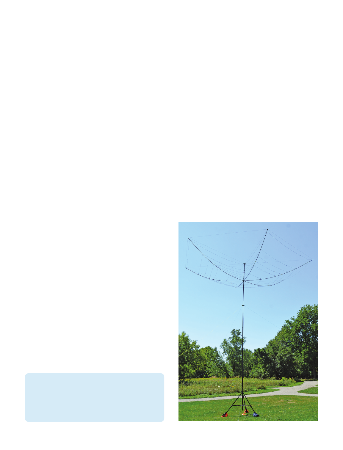
Each of the six spreader arms is unfolded, placed on the
ground, and inserted into the lower section of the VFP
hub, which is facing upwards. The next step is deploying
the perimeter tension cords by inserting the toggle into
the next arm insertion point. Then,
insert the remaining tension cords
into the peripheral ends of the hub.
After adding the tension cords, you
have what looks like an upside-down
umbrella laying on the ground.
Table 1 — Buddipole BuddiHEX (HX6)
Portable Hexagonal Beam Antenna
Manufacturer advertised specifications
(not tested by the ARRL lab)
Frequency coverage: 6 to 20 meters
(V)SWR: <1.5:1 at band center
Maximum power rating: 1500 W
Connector: BNC (optional PL-259)
Antenna weight: 10 pounds (4.54 kilograms)
Turning radius: 11 feet (3.35 meters)
Gain: 8 dB (30-feet elevation above ground)
Antenna type: Hexagonal beam antenna
Dimension: Not specied
Wind load area: 4 square feet
Figure 8 — Sportube case.

40 December 2022 QST www.arrl.org
width that an antenna tuner is not required. Everything
works as designed out of the box. On my rst deploy-
ment, I used no tools or measuring tape and was trans-
mitting an hour later.
During a POTA activation at Mary Lake, VE-5549, I was
working a pileup into the southern US on 20 meters with
the antenna pointed south. I used the Yaesu FT-891
transceiver and Bioenno LiFePO4 12 V 12 Ah battery.
Mike, CU3HY, in Azores, Portugal, called me and was
coming in 5 by 5. I rotated the beam toward Europe
using the hand crank. I then had a 5 by 8 signal report
that allowed a 20-minute QSO to discuss a future trip to
the islands for a SOTA activation. The BuddiHEX proved
itself with improved signal reports both ways. I found that
the antenna provided several S-units of improvement
over my vertical dipole antenna on transmit and receive.
The front-to-back ratio was also useful, with as much as
ve S-units. This allowed me to work Europeans while
reducing the US signals behind me, causing less
interference. On-air tests also provided similar
results, with the BuddiHEX performing admirably.
This antenna has also allowed me to null out noise
sources on 6 meters and work a weak KP4 station that
was not possible with my Buddistick antenna as I did an
A/B antenna check.
The wire elements are color coded and pre-tuned, and
they are stored on the included line winders. The color-
coded marks on the arms help to simplify the wire ele-
ment installation. The 20-meter band connects the end
wire to the top of the VFP hub. Clip it onto the spreader
using the same color-coded clips (facing upward), and
walk around until the other connection is made. The
antenna element-binding points are hand-tightened. Do
this for the other ve bands. Attach the BNC feed point
to the top banana jacks on the VFP, and add your coax
assembly. I use the Buddipole coax, as it comes with
end covers, uses military-grade coax, and is easy to
coil and uncoil. The nal step is to install a special ten-
sioning cord to the driven element area at the front of the
director section to maintain the hexagonal shape and to
keep it tight.
I lift the antenna assembly off the ground, holding the
VFP hub in one hand and an element in the other, and
place it onto the Mastwerks mast. The two components
t together perfectly. Now I can push the mast up to its
operating height, and the preloaded guy wires are in
place. I connect the coax to my radio and check my
SWR, and I’m now on the air. I did an SWR sweep for all
of the bands and found the SWR for all of them to be
under 1.5 (see Figures A – F). There is enough band-
50.0 51.0 52.0 53.0
54.0
1.0
1.5
2.0
2.5
Frequency (MHz)
SWR
QS2212-ProdRev-A
6 meters
28.528.0 29.0 29.5 30.0
1.0
1.5
2.0
2.5
Frequency (MHz)
SWR
QS2212-ProdRev-B
10 meters
24.9424.89 24.99
1.0
1.5
2.0
2.5
Frequency (MHz)
SWR
QS2212-ProdRev-C
12 meters
21.0 21.1 21.2 21.3 21.4
1.0
1.5
2.0
2.5
Frequency (MHz)
SWR
QS2212-ProdRev-D
15 meters
18.11818.068 18.168
1.0
1.5
2.0
2.5
Frequency (MHz)
SWR
QS2212-ProdRev-E
17 meters
14.0 14.1 14.2 14.3
1.0
1.5
2.0
2.5
3.0
Frequency (MHz)
SWR
QS2212-ProdRev-F
20 meters
Figure A — 6-meter SWR sweep. Figure B — 10-meter SWR sweep. Figure C — 12-meter SWR sweep.
Figure D — 15-meter SWR sweep. Figure E — 17-meter SWR sweep. Figure F — 20-meter SWR sweep.

www.arrl.org QST December 2022 41
BuddiHEX Hacks
One modication I made immediately
was to use some plumbing bits to
make a mast adapter, which allowed
me to use an Arrow antenna on top
of the Mastwerks mast. This
plumbing tting has the same
NPTs as the Buddipole (see
Figure 9).
The 40/20-meter antenna
is an inverted
V
-linked
dipole using a PackTenna
Mini balun with switches
to add or remove the
40-meter legs as needed.
I use a small Nite Ize carabiner
clip to attach the balun to the upper guy ring. So now I
can cover 40 – 6 meters with two antennas on one mast,
deployed in less than 30 minutes, with no tools and no
tuning required.
I am also looking at adding a dual-band VHF/UHF
antenna on the top of the VFP hub, which could allow me
coverage of those bands as well.
The BuddiHEX bundle does everything I expected. It
performs well on all bands, doesn’t require an antenna
tuner, and can quickly and easily be deployed by a single
person. If you are looking to add a directional antenna to
your portable go-box, the BuddiHEX may be the right
choice for you.
Conclusion
The BuddiHEX provided me the opportunity to make
better contacts, farther, with less noise. The system is an
investment, and the build quality is excellent. I see many
years of usage. This antenna can be left outdoors in a
permanent type of installation, but this may not be
designed for harsh winters and rain-soaked environments.
Manufacturer: Buddipole, Inc. 3028 SE 59th Ct. #600,
Hillsboro, OR 97123. www.buddipole.com. Price: $599;
7m Mastwerks Tripod and Mast System, $659; Sportube
Series 2 transport case, $249.
Figure 9 —
Mast adapter.
Reviewed by Mark Wilson, K1RO
k1ro@arrl.net
Building on the TR-25 40/20-meter CW transceiver
kit reviewed in the December 2021 issue of QST, the
TR-35 from John Dillon, WA3RNC, adds coverage of
30 and 17 meters, along with narrow/wide CW lter
choices and SSB reception. The transceiver is available
as a kit or assembled and tested. We ordered the kit
version for this review.
Like the TR-25, the TR-35 was designed with portable
operation in mind. It’s compact and lightweight, and all
functions are controlled by front-panel switches and
knobs (no menus). The radio requires 9.5 – 14 V dc and
still produces 4 – 5 W RF output at the low end of that
range. Maximum power output is 8 – 10 W with a 14 V
dc power source. The transceiver draws about 100 mA
on receive and 1 A on transmit, so a modest 12 V bat-
tery will power your operation for several hours.
Although you can use any suitable battery or power
supply, the WA3RNC website (www.wa3rnc.com) indi-
cates that the TR-35 is optimized for operation from
WA3RNC TR-35 40/30/20/17-Meter
CW Transceiver Kit
Bottom Line
The WA3RNC TR-35 40/30/20/17-meter CW
transceiver kit is well thought out and pack-
aged, making it an attractive project for
anyone who has learned the basics of sol-
dering and PC board construction. The radio
works well and is easy to use, and it is espe-
cially suited to portable operation where size,
weight, and power requirements matter.

42 December 2022 QST www.arrl.org
Table 2
WA3RNC TR-35 CW Transceiver
Manufacturer’s Specifications Measured in the ARRL Lab
Frequency coverage: Full coverage of the As specied.
40-, 30-, 20-, and 17-meter amateur
band, with extended receive above
and below.
Power requirement: 9.5 – 14 V dc at Receive: Typically 116 mA at 9.5 – 14 V dc.
<100 mA receive; 1 A transmit Transmit: Typically 1.1 A at 13.8 V dc
at 10 V. and 5 W output power.
Mode of operation: CW transmit and As specied.
receive; SSB receive only.
Receiver Receiver Dynamic Testing
Sensitivity: –125 dBm. Noise oor (MDS):
7 MHz, –132 dBm
10.1 MHz, –132 dBm
14 MHz, –133 dBm
18 MHz, –134 dBm
Blocking gain compression dynamic range: Blocking gain compression dynamic range:
Not specied. 20/5/2 kHz offset
7 MHz 105/105/104 dB
14 MHz 106/106/105 dB
Reciprocal mixing dynamic range: 14 MHz, 20/5/2 kHz offset: 103/95/91 dB
Not specied.
ARRL Lab Two-Tone IMD Testing
Measured Measured
Band Spacing IMD Level Input Level IMD DR
14 MHz 20 kHz –133 dBm – 52 dB 81 dB
–97 dBm – 40 dB
14 MHz 5 kHz –133 dBm – 51 dB 82 dB
–97 dBm – 39 dB
14 MHz 2 kHz –133 dBm – 51 dB 82 dB
–97 dBm – 38 dB
Second-order intercept point: Not specied.* +43 dBm at 14 MHz.
IF/audio response: Better than 350 Hz at Range at –6 dB points:
–6 dB (CW narrow setting). CW narrow: 630 – 920 Hz (290 Hz);
SSB: 350 – 3045 Hz (2695 Hz).
Transmitter Transmitter Dynamic Testing
Power output, 7/10.1/14/18 MHz: 7/10.1/14/18 MHz:
At 14 V dc, 8.5/10/9.5/8.5 W As specied.
At 9.5 V dc, 4.0/4.9/4.5/4.4 W As specied.
Spurious-signal and harmonic >62 dB (see Figure G). Complies
suppression: 52 dB. with FCC emission standards.
CW keying characteristics: Not specied. See Figures H and I.
Transmitted phase noise: Not specied. See Figure J.
Transmit-receive turnaround time: S-9 signal, 16.3 ms.
Not specied.
Size (height, width, depth): 2 ×6 ×3.25 inches including protrusions. Weight: 11 ounces.
*Second-order intercept point was determined using S-5 reference.
three series-connected external 18650 cells. These inex-
pensive 3.7 V rechargeable Li-ion cells, typically rated at
2500 – 3000 mAh, are widely available.
Building the Kit
The kit includes two PC boards, the case, and three
strips of components packaged in bubbles. The package
includes printed assembly and operating instructions and
full schematic diagrams. These documents are also avail-
able as PDFs on the WA3RNC website. As delivered, the
QS2212-PR163
T-R 250 50
TX-RX Turnaround Time (ms)
16.3
θ
TX
50 kHz –137
10 kHz –132
–110 –150
Transmit Phase Noise (dB)
–90 –150
5 kHz –90
500 Hz –45
–55 –95
Transmit Keying Sidebands (dB)
–35 –70
bw
TX
20 m 82
50 110
2 kHz Third-Order IMD Dynamic Range (dB)
I3
2k
20 m 105
40 m 104
70 140
2 kHz Blocking Gain Compression (dB)
2k
BG
2k
RM
20 m 91
60 140
2 kHz Reciprocal Mixing Dynamic Range (dB)
20 m 81
50 110
20 kHz Third-Order IMD Dynamic Range (dB)
I3
20k
20 m 106
40 m 105
70 140
20 kHz Blocking Gain Compression (dB)
20k
BG
60 140
20 kHz Reciprocal Mixing Dynamic Range (dB)
20k
RM
20 m 103
WA3RNC TR-35
Key Measurements Summary
PC boards are populated with several hundred surface-
mounted components, and the builder adds about 55
through-hole parts.
The PC boards are called the upper and lower boards,
referring to how they will be positioned in the nal
assembly. There is one strip of components for the
upper board, one for the lower board, and another with
knobs and connectors for the nal assembly. Within
each strip, the components are arranged in the order

www.arrl.org QST December 2022 43
2010 30 40 50 60 70 80 90 100
Time (milliseconds)
0
QS2212-Prodrev-G
Frequency (MHz)
0 10 20 30 40 50 60 70 80 90 100
Response (dB)
–100
–90
–80
–70
–60
–50
–40
–30
–20
–10
0
QS2212-Prodrev-H
1
Frequency (kHz)
fc
fc−4 fc−2 fc+2 fc+4
Response (dB)
–100
–90
–80
–70
–60
–50
–40
–30
–20
–10
0
QS2212-Prodrev-I
Figure H — CW keying waveform for the
WA3RNC TR-35 showing the rst two dits using
external keying. Equivalent keying speed is
60 WPM. The upper trace is the actual key
closure; the lower trace is the RF envelope.
Horizontal divisions are 10 ms. The trans-
ceiver was being operated at 5 W output on
the 14 MHz band. Rise time is 3.6 ms, and
fall time is 4 ms. First dit: on delay, 12 ms; o
delay, 7.8 ms. Second dit: on delay, 14.9 ms;
o delay, 7.9 ms.
Figure G — Spectral display of the WA3RNC
TR-35 transmitter output. Power output is 5 W
on the 18.068 MHz band. This plot shows the
output spectrum from 0 to 100 MHz. The second
harmonic is down 82 dB from the carrier, and
the third harmonic is down more than 85 dB.
Close-in spurious emissions are down 63 dB.
The vertical scale is 10 dB per division.
Figure I — Spectral display of the WA3RNC
TR-35 transmitter during keying sideband
testing. Equivalent keying speed is 60 WPM
using external keying. Spectrum analyzer reso-
lution bandwidth is 10 Hz, and the sweep time is
30 seconds. The transmitter was being operated
at 5 W PEP output on the 14 MHz band, and this
plot shows the transmitter output ±5 kHz from
the carrier. The reference level is 0 dBc, and the
vertical scale is 10 dB per division.
Lab Notes: WA3RNC TR-35
Four-Band HF Transceiver
The TR-35 tested to be a decently per-
forming radio for its price class. For a
small and portable rig that will often
be used by amateurs without the big
antennas often used with big rigs, this
rig delivers reasonable performance.
Its noise oor (MDS) is more than ade-
quate for HF. This means that when it is
hooked up to almost any HF antenna,
the limiting factor is external noise, not
the sensitivity of the radio.
Dynamic range is also reasonable for a
radio of this price class. It may not be
the radio to use with a Yagi antenna
during a major contest, but it performs
well enough that overload should not be
an issue with the modest antennas or
when the band is not chock-full of big-
gun signals.
As can be seen in Figure H, when keyed
at 60 WPM, the keying showed a slight
shortening of the dits, but even at this
speed, this will sound okay on the air.
(At lower speeds, this shortening would
hardly be noticed.) The shape of the
keyed waveform is smooth, and although
the rise and fall times are a bit faster than
the 5 – 6 ms that ARRL recommends for
minimal keying sidebands (clicks), the rig
won’t generate signicant key clicks up
and down the band.
The rig achieved full power on all bands
and operates well over a wide voltage
range, making it well suited to operating
in the eld for camping or some of the
QRP operating activities. Harmonics are
better than the rules require, and trans-
mit phase noise is good. — Ed Hare,
W1RFI, ARRL Laboratory Manager
−
150
−
140
−
130
−
120
−
110
−
100
Level (dBc/Hz)
100 Hz 1 kHz 10 kHz 100 kHz 1
MHz
Frequency Offset
QS2212-Prodrev-J
14 MHz
50 MHz
144 MHz
432 MHZ
Figure J — Spectral display of the WA3RNC
TR-35 transmitter output during phase-noise
testing. Power output is 5 W on the 14 MHz
band. The carrier, o the left edge of the
plot, is not shown. This plot shows phase
noise at 100 Hz – 1 MHz from the carrier.
The reference level is –100 dBc/Hz, and the
vertical scale is 10 dB per division.
they will be used during assem-
bly. Everything is extremely well
organized — no hunting through
a pile of parts or guessing at
component values. The parts
packaging and illustrated step-
by-step instructions make
assembly quick and easy. I
spent an afternoon stuffing the
boards, and I did the nal
assembly and checkout the next
day, perhaps 4 to 5 hours total.
No special tools are needed for
assembly — just a good sol-
dering iron with a ne tip and
thin-gauge solder, ush cutters
for trimming component leads,
and some clear nail polish for
securing several nuts. I also
needed a magnier and good
lighting for soldering to tiny com-
ponent pads. A digital multimeter
is required for a few nal checks
and adjustments.
I built the upper board rst (see
Figure 10). This board has all of
the switches and controls, the
organic LED (OLED) display
and indicator LEDs, and an
ATmega328P microcontroller.
Jacks for a keyer paddle, an
external key, and headphones
are mounted under the board,
along with a couple of potentiom-
eters. The nal assembly steps
for this board involve placing
three toggle switches, the tuning
encoder, and four potentiome-
ters, and then using the top half
of the case to align everything
before soldering. The board and
components must be rmly
secured before soldering, and
the instructions recommend
some plastic clips from Harbor
Freight or rubber bands. I used
two small adjustable clamps from
my toolbox. The upper and lower
boards are closely spaced, and
the instructions clearly indicate
which components require spe-
cial attention during installation to
ensure that the nal assembly
goes smoothly. For example,
some parts must be mounted

44 December 2022 QST www.arrl.org
Figure 11 — The lower board has the RF and audio components.
The nal amplier FET is on its heatsink in the center of the board.
All of the toroids are pre-wound with tinned leads. The instructions
clearly indicate the core color and number of turns, so you can
double-check that you have the right part. The numbered and
matched crystals for the narrow CW lter are along the bottom edge.
Figure 10 — The upper board contains the display and controls.
When this photo was taken, the 16-pin connectors to join the two
PC boards had not been installed, and the protective lm was still
in place on the OLED display. The microcontroller will be plugged
into the empty socket in one of the nal steps.
ush with the board, some are bent over, and others
require closely trimmed leads.
The lower board carries most of the receiver and trans-
mitter RF circuitry (see Figure 11). The IRF510 nal
amplier is mounted with a small heatsink, mica insu-
lator, and plastic washer. Mounting the nal amplier and
heatsink requires some care. The IRF510 leads have to
be bent correctly before soldering so that the insulating
material lines up. There are seven toroid inductors and a
bilar wound transformer, and these are all supplied pre-
wound with tinned leads. They install just like any other
part. A crystal lter following the mixer uses four matched
crystals in series. The crystals are labeled 1 – 4 and are
installed in the corresponding spot on the PC board.
One of the things I really like about this kit is that all of
the connections between the upper and lower boards
are made using two 16-pin connectors. All of the
switches and controls mount to the boards, so there are
no interconnecting wires at all. The upper and lower
boards simply plug together using the two connectors
and are secured with machine screws and spacers.
Adjustments and Final Assembly
At this point, the radio is fully assembled but not placed
in the case until you perform some checks and adjust-
ments. Before applying power to the boards, the instruc-
tions show a few simple ohmmeter checks for power bus
shorts. Then connect an antenna and speaker or head-
phones, apply power, and listen for signals on the four
bands while checking operation of the display and
controls. At this point, the receiver sounded deaf, so I
stopped there to recheck my work. Because of the way
the board interconnections are done with the two 16-pin
connectors, it was easy to pop the boards apart and
inspect everything with a magnier, revealing a bad
solder joint on the lter switch. With that xed, the
receiver sounded ne on all bands, so I moved on to the
nal adjustments with the radio connected to a watt-
meter and dummy load.
Several trimmer potentiometers need to be adjusted. The
rst trimmer is set to just barely light the blue SIG LED
with no signal present. It glows brightly with strong
received signals. The next step requires a multimeter in
series with the power supply that can measure current of
around 100 mA with a resolution of a few milliamps (most
digital multimeters will work here). In this multistep pro-
cess, watch the current draw while adjusting the BIAS
trimmer to set the operating point for the nal amplier
FET. This should be a set-and-forget adjustment. Next,
adjust the sidetone level trimmer for comfortable lis-
tening.
Now adjust the low-voltage alarm trimmer to light the red
LOW BATT LED when the power supply voltage drops
too low, helping to keep your battery from excessive dis-
charge. The alarm range is about 9 – 11 V. I set mine
with an adjustable power supply. This isn’t a critical
adjustment — it’s just an alarm to warn you that your
battery is getting low, and it doesn’t affect operation of
the radio.
The nal trimmer centers the audio band-pass lter fre-
quency at 700 Hz. The instructions suggest using an
oscilloscope or audio meter to adjust for maximum
signal, but it’s easy enough to do it by ear.
With the trimmers adjusted, it’s time to put the radio in
the case and get on the air.
Connections and Controls
The left side of the radio has three jacks: a coaxial dc
power jack, a 3.5-millimeter
KEY
jack for an external key
or keyer, and another 3.5-millimeter jack for paddles for
the internal keyer. You can have both an external key

www.arrl.org QST December 2022 45
and paddles for the internal keyer connected at the
same time and switch back and forth. The right side has
a 3.5-millimeter jack for headphones or a speaker, along
with the BNC antenna jack.
Be sure to read the instructions for the headphone jack.
In the review kit, which uses a 12/2021 Rev. A3 upper
board, the jack will work with headphones with a standard
mono or stereo plug. For a speaker, use a stereo plug
with the ground connection made to the ring terminal.
Connecting the tip and ring together on a stereo plug will
cause a short to ground and damage the audio amplier.
The 02/2022 Rev. B upper board currently shipping is
wired for a 3.5-millimeter mono plug, so you will need an
adapter if you have stereo headphones and want sound
in both ears. The instructions show a modication to the
board that will allow both earpieces to play without an
adapter, but once the modication is made, connecting
a mono plug will damage the audio amplier.
Although an ATmega328P microcontroller runs the
TR-35 control functions, the radio was designed to be
simple to operate. Instead of menus, it uses hardware
switches and knobs for all functions.
Pressing up on the
BAND/RIT
switch cycles through 40,
30, 20, and 17 meters. The
TUNE
encoder at the upper
right adjusts the operating frequency, with selectable
10 Hz, 100 Hz, and 1 kHz tuning steps. Engage receiver
incremental tuning (RIT) by pressing the
BAND/RIT
toggle and turning the
TUNE
knob to adjust the offset.
The RIT range is ±5 kHz, and the orange
RIT
LED lights
when active. Although the receiver tuning range extends
beyond the ham bands, the TR-35 will not transmit past
the band edges.
Pressing up on the
RCVR MODE/AUX
switch toggles
between narrow and wide CW lters, and a longer click
selects SSB reception. In SSB mode, the receiver auto-
matically selects lower sideband for 40 meters and
upper sideband for 20 and 17 meters. You can store one
operating frequency/mode combination as the initial set-
ting for each band.
Pressing down on this switch (
AUX
position) activates
the internal memory keyer record and playback func-
tions. The two memories can store up to 125 characters
each, with the memory to use selected by tapping the
dit or dah paddle. The iambic keyer range is about
5 – 45 WPM, adjusted with the
KEYER
knob.
According to the manual, the TR-35 is designed for CW
duty cycle use and cautions against transmitting con-
tinuously for more than 10 seconds or so at full power.
To protect the transmitter from damage, the TR-35 uses
a polyfuse, a device that increases resistance as tem-
perature increases over time, to fold back power if it gets
too hot. I never experienced power foldback during
normal CW operation, even when CQing and making
contacts for extended periods.
On the Air
I nished the TR-35 kit on the weekend of the IARU HF
World Championship, so the bands were packed with
stations. Tuning through 20 meters in the narrow CW
mode, I was impressed with how well the receiver was
able to separate closely spaced strong signals. In three
short operating sessions that totaled about an hour, I
worked 45 stations in 19 different DXCC countries. (My
antenna is a two-element beam at 25 feet.)
With its small size, simple controls, and modest power
requirements, the TR-35 is a joy to use for portable
operation. I set up the TR-35, a small battery, and
modest antennas for activations at six nearby state for-
ests and parks for the Parks on the Air®(POTA) and
World Wide Flora and Fauna (WWFF) programs. I made
about 160 contacts using all four bands, including sta-
tions in Alaska, Europe, and the Caribbean.
The OLED display characters are crisp and easy to read
despite the small size. It can, however, be difficult to
read outdoors in bright sunlight if you’re operating in an
exposed area. There’s a “reverse optic display” mode
that changes the display to black numbers on a blue
background. While that helped somewhat, at times I
ended up using my hat to throw a bit of shadow on the
radio when I needed to read the frequency display.
The solid-state full break-in (QSK) is terric. Switching is
practically instantaneous, with no clicking or popping, so
it’s easy to monitor the frequency between sent charac-
ters.
The transmit offset is xed at about 700 Hz, and the
sidetone is a sample of the transmitted signal, not gen-
erated by a separate oscillator. During nal assembly, I
had adjusted the internal sidetone level potentiometer on
the lower PC board for comfortable listening on a quiet
band. With a lot of activity on the air, I sometimes
wanted to increase the sidetone level to make it easier to
hear when competing with strong received signals.
While I could accomplish that by reducing the RF gain to
quiet the received signals, a small hole in the case to
adjust the level trimmer for changing band conditions
might be helpful.
Manufacturer: John Dillon, WA3RNC, www.wa3rnc.
com. Price: $279 (kit); precision optical encoder, add
$38; factory wired and tested, add $100.
Other manuals for K45
1
Table of contents
Other K1EL Modem manuals
Popular Modem manuals by other brands

I-DEN
I-DEN iO1000 Detailed service manual

Multitech
Multitech MultiModem MT2834ZDX Series user guide

Black Box
Black Box RM1600 Specifications

BridgeComSystems
BridgeComSystems SkyBridge Plus quick start guide

Multitech
Multitech MultiModem EDGE reference guide

Multitech
Multitech MultiModem DID MT5634ZBA-DID user guide