K2L OptoLyzer MOCCA compact FD User manual

ISBN: 978-1-5224-2575-5
Copyright © 2017 - 2018 K2L GmbH & Co. KG ("K2L"). All rights reserved.
Please make sure that all information within a document marked as 'Confidential' or 'Restricted Access' is handled solely in accordance with the agreement pursuant to which
it is provided, and is not reproduced or disclosed to others without the prior written consent of K2L. The confidential ranking of a document can be found in the footer of every
page. This document supersedes and replaces all information previously supplied. The technical information in this document loses its validity with the next edition. Although
the information is believed to be accurate, no responsibility is assumed for inaccuracies. Specifications and other documents mentioned in this document are subject to change
without notice. K2L reserves the right to make changes to this document and to the products at any time without notice. Neither the provision of this information nor the sale
of the described products conveys any licenses under any patent rights or other intellectual property rights of K2L or others. The products may contain design defects or errors
known as anomalies, including but not necessarily limited to any which may be identified in this document, which may cause the product to deviate from published descriptions.
Anomalies are described in errata sheets available upon request. K2L products are not designed, intended, authorized or warranted for use in any life support or other
application where product failure could cause or contribute to personal injury or severe property damage. Any and all such uses without prior written approval of an officer of
K2L will be fully at your own risk. The K2L logo is a trademark of K2L. Other names mentioned may be trademarks of their respective holders.
K2L disclaims and excludes any and all warranties, including without limitation any and all implied warranties of merchantability, fitness for a particular purpose, title, and
against infringement and the like, and any and all warranties arising from any course of dealing or usage of trade. In no event shall K2L be liable for any direct, incidental,
indirect, special, punitive, or consequential damages; or for lost data, profits, savings or revenues of any kind; regardless of the form of action, whether based on contract;
tort; negligence of K2L or others; strict liability; breach of warranty; or otherwise; whether or not any remedy of buyer is held to have failed of its essential purpose, and whether
or not K2L has been advised of the possibility of such damages.
© 2017 - 2018 K2L GmbH & Co. KG DS60001526B
K2L USER MANUAL
OptoLyzer®MOCCA compact FD

OptoLyzer MOCCA Devices
DS60001526B 2 © 2017 - 2018 K2L GmbH & Co. KG
K2L USER MANUAL
Table of Contents
Chapter 1 Preface. . . . . . . . . . . . . . . . . . . . . . . . . . . . . . . . . . . . . . . . . . . . . . . . . . . . . . . . . . . . 6
1.1 Intended Use . . . . . . . . . . . . . . . . . . . . . . . . . . . . . . . . . . . . . . . . . . . . . . . . . . . . . . . . . . . . . . . . . 6
1.2 Scope of Delivery . . . . . . . . . . . . . . . . . . . . . . . . . . . . . . . . . . . . . . . . . . . . . . . . . . . . . . . . . . . . . . 6
1.3 Overview OptoLyzer MOCCA Family . . . . . . . . . . . . . . . . . . . . . . . . . . . . . . . . . . . . . . . . . . . . . . . 7
1.4 Definitions of Terms . . . . . . . . . . . . . . . . . . . . . . . . . . . . . . . . . . . . . . . . . . . . . . . . . . . . . . . . . . . . 8
1.5 References . . . . . . . . . . . . . . . . . . . . . . . . . . . . . . . . . . . . . . . . . . . . . . . . . . . . . . . . . . . . . . . . . . . 9
Chapter 2 Safety Instructions . . . . . . . . . . . . . . . . . . . . . . . . . . . . . . . . . . . . . . . . . . . . . . . . . 10
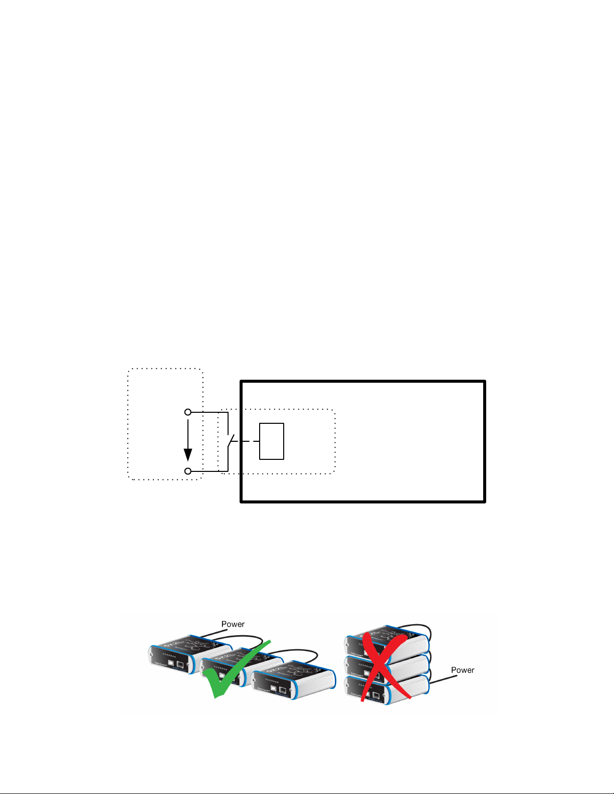
2.1 Supply and Synchronization . . . . . . . . . . . . . . . . . . . . . . . . . . . . . . . . . . . . . . . . . . . . . . . . . . . . . 10
2.2 Relay . . . . . . . . . . . . . . . . . . . . . . . . . . . . . . . . . . . . . . . . . . . . . . . . . . . . . . . . . . . . . . . . . . . . . . 10
2.3 Restrictions in Operation . . . . . . . . . . . . . . . . . . . . . . . . . . . . . . . . . . . . . . . . . . . . . . . . . . . . . . . 10
Chapter 3 Definitions Limit Class . . . . . . . . . . . . . . . . . . . . . . . . . . . . . . . . . . . . . . . . . . . . . 11
3.1 Emission . . . . . . . . . . . . . . . . . . . . . . . . . . . . . . . . . . . . . . . . . . . . . . . . . . . . . . . . . . . . . . . . . . . . 11
Chapter 4 Introduction . . . . . . . . . . . . . . . . . . . . . . . . . . . . . . . . . . . . . . . . . . . . . . . . . . . . . . 12
4.1 Feature Summary. . . . . . . . . . . . . . . . . . . . . . . . . . . . . . . . . . . . . . . . . . . . . . . . . . . . . . . . . . . . . 12
4.2 Block Diagram . . . . . . . . . . . . . . . . . . . . . . . . . . . . . . . . . . . . . . . . . . . . . . . . . . . . . . . . . . . . . . . 13
4.3 Properties of Supported Bus Systems . . . . . . . . . . . . . . . . . . . . . . . . . . . . . . . . . . . . . . . . . . . . . 14
4.3.1 CAN . . . . . . . . . . . . . . . . . . . . . . . . . . . . . . . . . . . . . . . . . . . . . . . . . . . . . . . . . . . . . . . . . . . 14
4.3.1.1 High-Speed Transceiver...........................................................................................14
4.3.2 CAN FD . . . . . . . . . . . . . . . . . . . . . . . . . . . . . . . . . . . . . . . . . . . . . . . . . . . . . . . . . . . . . . . . 14
4.3.3 FlexRay . . . . . . . . . . . . . . . . . . . . . . . . . . . . . . . . . . . . . . . . . . . . . . . . . . . . . . . . . . . . . . . . 14
4.3.4 LIN . . . . . . . . . . . . . . . . . . . . . . . . . . . . . . . . . . . . . . . . . . . . . . . . . . . . . . . . . . . . . . . . . . . . 14
4.3.5 MOST . . . . . . . . . . . . . . . . . . . . . . . . . . . . . . . . . . . . . . . . . . . . . . . . . . . . . . . . . . . . . . . . . 14
4.3.5.1 MOST150 .................................................................................................................15
4.3.5.2 SpyNIC for MOST..................................................................................................... 15
4.3.5.3 StressNIC for MOST.................................................................................................15
4.3.6 Ethernet . . . . . . . . . . . . . . . . . . . . . . . . . . . . . . . . . . . . . . . . . . . . . . . . . . . . . . . . . . . . . . . . 15
4.3.7 Sleep Mode . . . . . . . . . . . . . . . . . . . . . . . . . . . . . . . . . . . . . . . . . . . . . . . . . . . . . . . . . . . . . 15
Chapter 5 Hardware Description . . . . . . . . . . . . . . . . . . . . . . . . . . . . . . . . . . . . . . . . . . . . . . 16
5.1 Front Panel . . . . . . . . . . . . . . . . . . . . . . . . . . . . . . . . . . . . . . . . . . . . . . . . . . . . . . . . . . . . . . . . . . 16
5.2 Rear Panel . . . . . . . . . . . . . . . . . . . . . . . . . . . . . . . . . . . . . . . . . . . . . . . . . . . . . . . . . . . . . . . . . . 20
Chapter 6 Pin Assignment of the Connectors . . . . . . . . . . . . . . . . . . . . . . . . . . . . . . . . . . . . 22
6.1 High-Speed CAN . . . . . . . . . . . . . . . . . . . . . . . . . . . . . . . . . . . . . . . . . . . . . . . . . . . . . . . . . . . . . 22
6.2 LIN / FlexRay . . . . . . . . . . . . . . . . . . . . . . . . . . . . . . . . . . . . . . . . . . . . . . . . . . . . . . . . . . . . . . . . 23
6.3 LIN / CAN FD 7/8 . . . . . . . . . . . . . . . . . . . . . . . . . . . . . . . . . . . . . . . . . . . . . . . . . . . . . . . . . . . . . 24
6.4 Synchronization and Power . . . . . . . . . . . . . . . . . . . . . . . . . . . . . . . . . . . . . . . . . . . . . . . . . . . . . 24
6.5 Digital Audio In/Out (S/PDIF) . . . . . . . . . . . . . . . . . . . . . . . . . . . . . . . . . . . . . . . . . . . . . . . . . . . . 25
6.6 Analog Audio In/Out . . . . . . . . . . . . . . . . . . . . . . . . . . . . . . . . . . . . . . . . . . . . . . . . . . . . . . . . . . . 25
6.7 USB . . . . . . . . . . . . . . . . . . . . . . . . . . . . . . . . . . . . . . . . . . . . . . . . . . . . . . . . . . . . . . . . . . . . . . . 25
6.8 Relay . . . . . . . . . . . . . . . . . . . . . . . . . . . . . . . . . . . . . . . . . . . . . . . . . . . . . . . . . . . . . . . . . . . . . . 26
6.9 Trigger/ECL . . . . . . . . . . . . . . . . . . . . . . . . . . . . . . . . . . . . . . . . . . . . . . . . . . . . . . . . . . . . . . . . . 26
6.10 MOST Network Connector . . . . . . . . . . . . . . . . . . . . . . . . . . . . . . . . . . . . . . . . . . . . . . . . . . . . . . 26
6.10.1 MOST150 Network Coaxial Connector . . . . . . . . . . . . . . . . . . . . . . . . . . . . . . . . . . . . . . . 26
6.10.1.1 Simplex Use Case ..................................................................................................27

OptoLyzer MOCCA Devices
© 2017 - 2018 K2L GmbH & Co. KG 3 DS60001526B
K2L USER MANUAL
6.10.1.2 Duplex Use Case....................................................................................................27
6.10.1.3 Duplex Endpoint Use Case ....................................................................................28
Chapter 7 Technical Specifications . . . . . . . . . . . . . . . . . . . . . . . . . . . . . . . . . . . . . . . . . . . . 29
Chapter 8 Maintenance . . . . . . . . . . . . . . . . . . . . . . . . . . . . . . . . . . . . . . . . . . . . . . . . . . . . . . 31
8.1 How to Release cPHY Connector . . . . . . . . . . . . . . . . . . . . . . . . . . . . . . . . . . . . . . . . . . . . . . . . 31
Chapter 9 Revision History . . . . . . . . . . . . . . . . . . . . . . . . . . . . . . . . . . . . . . . . . . . . . . . . . . 32

OptoLyzer MOCCA Devices
DS60001526B 4 © 2017 - 2018 K2L GmbH & Co. KG
K2L USER MANUAL
List of Figures
Figure 2.1 Relay Circuitry . . . . . . . . . . . . . . . . . . . . . . . . . . . . . . . . . . . . . . . . . . . . . . . . . . . . . . . . . . . . 10
Figure 2.2 Device Arrangement . . . . . . . . . . . . . . . . . . . . . . . . . . . . . . . . . . . . . . . . . . . . . . . . . . . . . . . 10
Figure 4.1 Block Diagram for OptoLyzer MOCCA compact FD . . . . . . . . . . . . . . . . . . . . . . . . . . . . . . . 13
Figure 4.2 Order of MOST Network ICs . . . . . . . . . . . . . . . . . . . . . . . . . . . . . . . . . . . . . . . . . . . . . . . . . 15
Figure 5.1 Front Panel - OptoLyzer MOCCA compact FD . . . . . . . . . . . . . . . . . . . . . . . . . . . . . . . . . . . 16
Figure 5.2 Rear Panel - OptoLyzer MOCCA compact FD. . . . . . . . . . . . . . . . . . . . . . . . . . . . . . . . . . . . 20
Figure 6.1 DE-9 Connector . . . . . . . . . . . . . . . . . . . . . . . . . . . . . . . . . . . . . . . . . . . . . . . . . . . . . . . . . . . 22
Figure 6.2 Pin Assignment of the Sync and Power Connector . . . . . . . . . . . . . . . . . . . . . . . . . . . . . . . . 24
Figure 6.3 Pin Assignment of the S/PDIF Connector . . . . . . . . . . . . . . . . . . . . . . . . . . . . . . . . . . . . . . . 25
Figure 6.4 Pin Assignment of the Analog Audio In/Out Connector . . . . . . . . . . . . . . . . . . . . . . . . . . . . . 25
Figure 6.5 Simplex Use Case . . . . . . . . . . . . . . . . . . . . . . . . . . . . . . . . . . . . . . . . . . . . . . . . . . . . . . . . . 27
Figure 6.6 Duplex Use Case . . . . . . . . . . . . . . . . . . . . . . . . . . . . . . . . . . . . . . . . . . . . . . . . . . . . . . . . . . 27
Figure 6.7 Duplex Endpoint Use Case . . . . . . . . . . . . . . . . . . . . . . . . . . . . . . . . . . . . . . . . . . . . . . . . . . 28
Figure 8.1 How To Release cPHY Connector. . . . . . . . . . . . . . . . . . . . . . . . . . . . . . . . . . . . . . . . . . . . . 31

OptoLyzer MOCCA Devices
© 2017 - 2018 K2L GmbH & Co. KG 5 DS60001526B
K2L USER MANUAL
List of Tables
Table 1.1 OptoLyzer MOCCA Family . . . . . . . . . . . . . . . . . . . . . . . . . . . . . . . . . . . . . . . . . . . . . . . . . . . . 7
Table 1.2 Definitions of Terms. . . . . . . . . . . . . . . . . . . . . . . . . . . . . . . . . . . . . . . . . . . . . . . . . . . . . . . . . . 8
Table 5.1 Connectors on the Front Panel . . . . . . . . . . . . . . . . . . . . . . . . . . . . . . . . . . . . . . . . . . . . . . . . 17
Table 5.2 LEDs . . . . . . . . . . . . . . . . . . . . . . . . . . . . . . . . . . . . . . . . . . . . . . . . . . . . . . . . . . . . . . . . . . . . 18
Table 5.3 Connectors on the Rear Panel . . . . . . . . . . . . . . . . . . . . . . . . . . . . . . . . . . . . . . . . . . . . . . . . 20
Table 6.1 Pin Assignment of Connector High Speed CAN 1/3/5. . . . . . . . . . . . . . . . . . . . . . . . . . . . . . . 22
Table 6.2 Pin Assignment of Connector High Speed CAN 2/4/6 . . . . . . . . . . . . . . . . . . . . . . . . . . . . . . 23
Table 6.3 Pin Assignment of Connector LIN / FlexRay A/B. . . . . . . . . . . . . . . . . . . . . . . . . . . . . . . . . . . 23
Table 6.4 Pin Assignment of Connector LIN / CAN 7/8 . . . . . . . . . . . . . . . . . . . . . . . . . . . . . . . . . . . . . . 24
Table 6.5 Pin Assignment of the Sync and Power Connector . . . . . . . . . . . . . . . . . . . . . . . . . . . . . . . . . 25
Table 6.6 Pin Assignment of the Relay Connector . . . . . . . . . . . . . . . . . . . . . . . . . . . . . . . . . . . . . . . . . 26
Table 6.7 Technical Values . . . . . . . . . . . . . . . . . . . . . . . . . . . . . . . . . . . . . . . . . . . . . . . . . . . . . . . . . . . 26
Table 7.1 Device and Bus Characteristics. . . . . . . . . . . . . . . . . . . . . . . . . . . . . . . . . . . . . . . . . . . . . . . . 29
Table 7.2 Mechanical Characteristics . . . . . . . . . . . . . . . . . . . . . . . . . . . . . . . . . . . . . . . . . . . . . . . . . . . 29
Table 7.3 Electrical Characteristics . . . . . . . . . . . . . . . . . . . . . . . . . . . . . . . . . . . . . . . . . . . . . . . . . . . . . 30
Table 9.1 Customer Revision History . . . . . . . . . . . . . . . . . . . . . . . . . . . . . . . . . . . . . . . . . . . . . . . . . . . 32

OptoLyzer MOCCA Devices
DS60001526B 6 © 2017 - 2018 K2L GmbH & Co. KG
K2L USER MANUAL
Chapter 1 Preface
1.1 Intended Use
The OptoLyzer MOCCA compact FD device is intended to be used for developing, testing, or analyzing
CAN®, CAN FD, FlexRay™, LIN®, or MOST®network based automotive products and systems by
persons with experience in developing automotive devices.
1.2 Scope of Delivery
The delivery covers the following:
OptoLyzer MOCCA compact FD device
Power cable
Coaxial MOST cable
USB cable
USB stick (license dongle, optional)
CAN termination resistors (optional)
SYNC cable V3 (optional)
CAN breakout cable (optional)
Check your shipment for completeness. If you have any objections, direct them to Sales@K2L.de.
Providing the delivery note number eases the handling.

OptoLyzer MOCCA Devices
© 2017 - 2018 K2L GmbH & Co. KG 7 DS60001526B
K2L USER MANUAL
1.3 Overview OptoLyzer MOCCA Family
Table 1.1 shows the feature sets of the OptoLyzer MOCCA family devices. The numbers indicate how
many interfaces/channels are available.
Table 1.1 OptoLyzer MOCCA Family
OptoLyzer MOCCA
compact
50e
compact
150o
compact
150c
compact
FD CLF CL FD LAN
INTERFACE
Analog Audio
Out
1x 1x 1x 1x 1x
Analog Line
IN
1x 1x 1x 1x 1x
CAN 6x 6x 6x 4xa
a. 4 CAN High Speed interfaces, neither low speed nor single wire CAN interfaces
6x 6x 4xb
b. The OptoLyzer MOCCA FD supports 6 CAN channels, 2 of them can be used as CAN FD channels.
2x
CAN FD 4x 2xc
c. The OptoLyzer MOCCA FD supports 6 CAN channels, 2 of them can be used as CAN FD channels.
Ethernet 1x 1x 1x 1x 1x 1x 4xd
d. 2x TX, 2x T1
FlexRaye
e. FlexRay A/B
1x 1x 1x 1x 1x 1x
LIN 6x 6x 6x 6x 6x 6x 6x
MOST 1x 1x 1x 1xf
f. MOST node is connected via I2C.
Relay 1x 1x 1x 1x 1x 1x
S/PDIF 1x 1x 1x 1x
Trigger/ECL 1x 1x 1x 1x 1x 1x
USB 1x 1x 1x 1x 1x 1x 1x 1x

OptoLyzer MOCCA Devices
DS60001526B 8 © 2017 - 2018 K2L GmbH & Co. KG
K2L USER MANUAL
1.4 Definitions of Terms
For better understanding of the following chapters, this section provides explanation to special terms
used in the description of the OptoLyzer MOCCA device user manual.
Table 1.2 Definitions of Terms
TERM / ABBREVIATION DESCRIPTION
ABI Automotive Bus Interface
ATS Automotive Test System
CAN Controller Area Network
CAN FD CAN with flexible data rate
cPHY Coaxial electrical physical layer; used e.g., in OptoLyzer MOCCA compact FD
variant
DDepth
DUT Device Under Test
ECL Electrical Control Line, a method to start a diagnosis process over the MOST
network.
FlexRay Automotive network communications bus system
H Height
LIN Local Interconnect Network
MDIX Medium Dependent Interface Crossover
MediaLB®Media Local Bus
MOST Media Oriented Systems Transport
RCA Type of electrical connector used for transmitting audio and video signals (also
known as cinch, introduced by Radio Corporation of America).
Sync Synchronization
S/PDIF Sony/Philips Digital Interconnect Format
USB Universal Serial Bus
WWidth

OptoLyzer MOCCA Devices
© 2017 - 2018 K2L GmbH & Co. KG 9 DS60001526B
K2L USER MANUAL
1.5 References
[1] Electrical Physical Layer Specification Version 2.0
Refer to FlexRay Consortium.
[2] International Organization for Standardization
http://www.iso.org
[3] Telecommunications Industry Association
http://www.tiaonline.org
[4] International Electrotechnical Commission
http://www.iec.ch

OptoLyzer MOCCA Devices
DS60001526B 10 © 2017 - 2018 K2L GmbH & Co. KG
K2L USER MANUAL
Chapter 2 Safety Instructions
2.1 Supply and Synchronization
When concatenating OptoLyzer MOCCA devices one of the two Sync/Power connectors is intended
to be used for the power supply and the other for cascading the OptoLyzer MOCCA device by using
the optional SYNC cable V3.
During cascading, caution has to be taken, since the first device in the chain can take the maximum
current of 3 A. Do not cascade more than eight devices in chain.
For all setups either a fuse of max. 4 A in the supply cable to the first device or the use of the current
limitation of the laboratory power supply is mandatory.
2.2 Relay
The Relay feature of the device is designed to switch other 12 V powered devices. The capability is
limited to 5 A at 16 V maximum. Always use core cable ends of appropriate length and diameter to
prevent unintended connections. Lengths and diameters depend on country-specific technical
specifications. Section 1.3, "Overview OptoLyzer MOCCA Family," on page 7 informs about which
device variant of the OptoLyzer MOCCA supports the Relay feature.
Figure 2.1 Relay Circuitry
2.3 Restrictions in Operation
The OptoLyzer MOCCA device integrates temperature sensitive components. Therefore do not cover
the device with any objects. Covering disables the passive cooling. Make sure to allow enough airflow
to the OptoLyzer MOCCA device, when the device is assembled. Do never place the running
OptoLyzer MOCCA device in a closed case or box. Do not stack any OptoLyzer MOCCA devices.
Figure 2.2 Device Arrangement
OptoLyzer MOCCA device
Relay
< 16 V
< 5 A
Power:
7..16 V
< 4 A
Customer
part

OptoLyzer MOCCA Devices
© 2017 - 2018 K2L GmbH & Co. KG 11 DS60001526B
K2L USER MANUAL
Chapter 3 Definitions Limit Class
3.1 Emission
The OptoLyzer MOCCA device has passed the requirements according to the standard
EN 55022:2010, class A.
Warning
The OptoLyzer MOCCA device is a class A product. In a domestic environment this product may cause
radio interference in which case the user may be required to take adequate measures.

OptoLyzer MOCCA Devices
DS60001526B 12 © 2017 - 2018 K2L GmbH & Co. KG
K2L USER MANUAL
Chapter 4 Introduction
The OptoLyzer MOCCA compact FD device is an out of the box automotive bus interface, combining
most of the current automotive field buses. The device features e.g., simulation via PC or can be used
as an analyzing device for the different automotive bus systems.
Due to its PC compatible connections including USB 2.0 and 10/100 Mbit/s Ethernet, it is easily
possible to control the embedded OptoLyzer MOCCA device software from the PC including
monitoring, tracing, and logging of data exchange over the different field bus systems. The OptoLyzer
MOCCA device provides comfortable spy and stress functionalities when used within a MOST network.
The OptoLyzer MOCCA compact FD device supports the bus systems CAN, CAN FD, LIN, FlexRay
or MOST network (speed grade 150). Refer to Section 1.3, "Overview OptoLyzer MOCCA Family," on
page 7 for details.
4.1 Feature Summary
The following list covers the key features of the hardware platform.
4 High-Speed CAN interfaces
4 CAN FD interfaces
1 FlexRay A/B interface
6 LIN interfaces
MOST150 network (cPHY)
USB 2.0 port supporting Full-Speed with 12 Mbit/s and High-Speed with 480 Mbit/s
Ethernet connection with 10/100 Mbit/s
S/PDIF coaxial input and output for audio streaming over MOST network
Analog audio input and output for audio streaming over MOST network
Generic trigger in-/output functionality or MOST network ECL support
Relay to switch external loads of up to 5 A
Time stamp synchronization with cascaded OptoLyzer MOCCA devices over power cables
SpyNIC for MOST
StressNIC for MOST
Simplex, duplex and duplex endpoint use case support

OptoLyzer MOCCA Devices
© 2017 - 2018 K2L GmbH & Co. KG 13 DS60001526B
K2L USER MANUAL
4.2 Block Diagram
The block diagram shows the features available for the OptoLyzer MOCCA compact FD device.
Figure 4.1 Block Diagram for OptoLyzer MOCCA compact FD
4x CAN High Speed (FD)
RAM
240 kByte
Flash
2 MByte
7 – 16 V
5 A
Debug &
Flash
10 / 100
BASE-TX
USB 2.0
Power
Supply
Trigger
LAN
89218
16
16
RAM
512 kByte
µC
Renesas
V850E2/FL4-H
Reset
Circuit
EEPROM FPGA
4
4
12
TJA1041
SN65HV
DA195
TJA1080
ATA656x
6x LIN
4x CAN
A
BFlexRay
High Speed
USB
EZ-FX2
Relay
5 A
4x
CAN
FD
6x LIN
16
RAM
240 kByte
16 FPGA
I²S / MediaLB
6-Pin
SpyNIC for
MOST
INIC
I²S
I²C
IN
OUT Analog
IN
OUT S/PDIF
cPHY
Codec
Analog/
Digital
StressNIC
for MOST
I²C

OptoLyzer MOCCA Devices
DS60001526B 14 © 2017 - 2018 K2L GmbH & Co. KG
K2L USER MANUAL
4.3 Properties of Supported Bus Systems
The OptoLyzer MOCCA device is intended to be used as stimulation, test and analysis device for
automotive field buses with DUTs connected to them. Therefore the design is constrained to ensure
the behavior to be as passive as possible.
4.3.1 CAN
The accuracy of CAN time stamps is 500 µs (or better).
4.3.1.1 High-Speed Transceiver
High-Speed CAN bus systems according to ISO 11898-2:2015 [2] are terminated with 120 Ωat each
end. Therefore the OptoLyzer MOCCA device does not terminate the bus. Transmission speed ranges
from 33.333 kbits/s to 1 Mbits/s.
4.3.2 CAN FD
CAN FD bus systems according to ISO 11898-2, ISO 11898-2:2016 [2] and SAE J2962-2 are
terminated with 120 Ωat each end. The OptoLyzer MOCCA compact FD device can be used at the
end of the bus system (in this case plug in the optional termination resistor, Section 1.2, "Scope of
Delivery," on page 6) or somewhere between the ends (in this case don’t plug in the optional
termination resistor). The accuracy of CAN FD time stamps is 1 µs. The OptoLyzer MOCCA compact
FD device supports up to 2 Mbits/s for each CAN FD channel in parallel. It is designed to operate with
up to 64 byte payload. CAN FD requires a prescaler (data phase) of 1 or 2 for 500 kbit/s and above
in case a custom bit rate (named StartCanFdExt in ABI Framework or ConfigureExtended in the K2L
Bus Framework) is used.
4.3.3 FlexRay
The termination of a FlexRay bus depends on the bus topology. Two terminations are mandatory in
each active branch. The OptoLyzer MOCCA device can be installed in various topologies. Therefore
a termination is not implemented in the device. Thus the terminations have to be realized in a different
way. In addition, the OptoLyzer MOCCA device does not act as a bus guardian.
The OptoLyzer MOCCA device provides one FlexRay interface and is able to switch from sleep mode
to wake-up mode stimulated by the FlexRay bus. The OptoLyzer MOCCA device is capable of
transmitting up to 10 Mbit/s as per "Electrical Physical Layer Specification Version 2.0" [1]. The
accuracy of FlexRay time stamps is 500 µs (or better) for the static part of the schedule.
4.3.4 LIN
Both LIN master and LIN slave functionality are supported. The accuracy of LIN time stamps is 1 µs.
The OptoLyzer MOCCA device supports a maximum transmission speed of 20 kbit/s.
4.3.5 MOST
The OptoLyzer MOCCA compact FD designed for a MOST150 network (cPHY) has a fixed clock mode
of 48 kHz. OptoLyzer MOCCA compact FD devices have an INIC, a SpyNIC for MOST and a
StressNIC for MOST on-board. If desired, the StressNIC for MOST can be added to the ring via
software. The accuracy of INIC MOST network time stamps is 500 µs (or better) for the node and 1 µs
for the spy.

OptoLyzer MOCCA Devices
© 2017 - 2018 K2L GmbH & Co. KG 15 DS60001526B
K2L USER MANUAL
When analyzing data e.g., when interpreting an acknowledged code, it is important to know how the
chips (INIC, SpyNIC for MOST, StressNIC for MOST) are arranged inside the OptoLyzer MOCCA
compact.
Figure 4.2 Order of MOST Network ICs
4.3.5.1 MOST150
Data exchange between the OptoLyzer MOCCA compact FD and the embedded OS81110 INIC is
realized by I2C. Right now control messages are supported.
4.3.5.2 SpyNIC for MOST
The OptoLyzer MOCCA compact FD has an appropriate SpyNIC for MOST on-board. The SpyNIC is
spying control, packet, and allocation messages. The accuracy of SpyNIC time stamps is 1 µs. In the
MOST150 network four synchronous/isochronous channels can be spied all the time.
4.3.5.3 StressNIC for MOST
The OptoLyzer MOCCA compact FD has an appropriate StressNIC for MOST on-board. The StressNIC
is supporting dedicated use cases for simulating some common network error situations (e.g., activity,
lock stress, buffer full simulation, etc.). By default the StressNIC for MOST is electrically bypassed but
can be enabled by appropriate software (e.g., ATS) (see Figure 4.2 on page 15).
4.3.6 Ethernet
Auto MDIX is supported, therefore the LAN interface can connect via straight and crossed patch
cables. The physical layer 100Base-TX is supported. Thereby the MAC address of the Ethernet
controller has a unique address. The accuracy of Ethernet time stamps is 500 µs (or better).
4.3.7 Sleep Mode
The OptoLyzer MOCCA device is able to scan the four CAN buses (1, 3, 4, 5 but not CAN FD) in
sleep mode and if stimulated to switch from sleep mode into wake-up mode. In addition, the OptoLyzer
MOCCA device can be woken-up via FlexRay, LIN or ECL. For controlling the sleep mode software
has to be developed by the customer on a PC.
OptoLyzer®MOCCA compact
RX
TX

OptoLyzer MOCCA Devices
DS60001526B 16 © 2017 - 2018 K2L GmbH & Co. KG
K2L USER MANUAL
Chapter 5 Hardware Description
The following chapter describes all connectors. To get details which feature set is supported refer to
Section 1.3, "Overview OptoLyzer MOCCA Family," on page 7.
5.1 Front Panel
Figure 5.1 depicts the front panel of the OptoLyzer MOCCA compact FD.
Figure 5.1 Front Panel - OptoLyzer MOCCA compact FD
All possible components of the front panel are described below:
Table 5.1 describes the connectors from left to right and top to down.
Table 5.2 describes the LEDs.

OptoLyzer MOCCA Devices
© 2017 - 2018 K2L GmbH & Co. KG 17 DS60001526B
K2L USER MANUAL
Table 5.1 Connectors on the Front Panel
INTERFACE SYMBOL DESCRIPTION
Analog Audio OUT The OptoLyzer MOCCA compact FD device provides an analog audio
out interface (a stereo headphone output). It has a 3.5 mm jack plug.
Output Power: Po, Max, Rms = 1.4 mW (at R = 16 Ω, Vout = 150 mVRMS)
The bandwidth (16 bit mono/stereo or 24 bit stereo) specified for this
interface is also used for the S/PDIF OUT and vice versa. Rx and Tx
transmission must cover the same bit number per channel. Refer to the
S/PDIF description inclusive examples in Table 5.3 on page 20.
ECL ECL can be used to start a diagnosis process over the MOST network
according to different ECL implementations. For the pin out refer to
Section 6.9, "Trigger/ECL," on page 26.
MOST (cPHY) The MOST150 network connectors base on a coaxial electrical physical
layer (cPHY) described separately below.
For the pin out refer to Section 6.10, "MOST Network Connector," on
page 26.
MOST (cPHY
Rx connector)
The connectors base on a coaxial electrical physical layer (cPHY). This
connector provides an Rx interface. It is used
in simplex use cases as Rx (indicated by the single-headed arrow).
MOST (cPHY
Rx/Tx connector)
The connectors base on a coaxial electrical physical layer (cPHY). This
connector provides a duplex interface (Rx/Tx connection). It is used
in duplex use cases as Rx/Tx (indicated by the double-headed
arrow).
MOST (cPHY
Tx and Rx/Tx
connector)
The connectors base on a coaxial electrical physical layer (cPHY). This
connector provides a Tx or a duplex interface (Rx/Tx connection). It is
used
in simplex use cases as Tx (indicated by the single-headed arrow)
and
in duplex use cases as Rx/Tx (indicated by the double-headed
arrow) and
in duplex endpoint use cases (indicated by the double-headed
arrow).
Program Reset The device can be reset by the push button. If the button is pressed for
less than 1 s, the device is reset. The same button is used for switching
into the flashing mode if it is pressed for more than 2 seconds. For
details see the “K2L Flasher Online Help” that is part of the shipment.
Analog Line IN The analog Line IN input impedance is 10 kΩ. The analog input is
converted into a digital stream with resolutions of 16 bits / channel
(mono/stereo) or 24 bits / channel (stereo). It has a 3.5 mm jack plug. It
is possible to use either the Analog Line IN or the S/PDIF IN interface.
Rx and Tx transmission must cover the same bit number per channel.
Refer to the S/PDIF description inclusive examples in Table 5.3 on
page 20.

OptoLyzer MOCCA Devices
DS60001526B 18 © 2017 - 2018 K2L GmbH & Co. KG
K2L USER MANUAL
The OptoLyzer MOCCA compact FD device offers seven LEDs. All LEDs except the Power LED are
tri-colors.
Relay The relay is able to switch 5 A as a potential free shutter.
For safety purposes refer to Chapter 2, "Safety Instructions," on page 10.
For the pin out refer to Section 6.8, "Relay," on page 26.
USB The USB port is a standard USB B-type receptacle.
LAN The LAN connector is an RJ45 receptacle according to TIA-568 [3].
Table 5.2 LEDs
INTERFACE SYMBOL DESCRIPTION COLOR DESCRIPTION
Active Active This LED indicates any
activity.
Red Reserved
Green Reserved
Blue
(Twinkling)
Slowly: Firmware running
Fast: Flash mode
Operation Op. This LED indicates different
states dependent on the
installed firmware (e.g., for
ATS etc.).
Red Depending on firmware
Green Depending on firmware
Blue Depending on firmware
CAN CAN This LED indicates the bus
state of the CAN FD bus.
Red Error
Green Operational
White
(Twinkling)
Bus activity
MOST MOST This LED indicates the bus
state of the MOST network.
The LED is only available for
variants that are supporting a
MOST network.
Red Error
Green Net on
White
(Twinkling)
Bus activity
FlexRay FR This LED indicates the bus
state of the FlexRay bus.
Red Error
Green Synced
White
(Twinkling)
Bus activity
Table 5.1 Connectors on the Front Panel
INTERFACE SYMBOL DESCRIPTION

OptoLyzer MOCCA Devices
© 2017 - 2018 K2L GmbH & Co. KG 19 DS60001526B
K2L USER MANUAL
LIN LIN This LED indicates the bus
state of the LIN bus.
Red Error
Green Operational
White
(Twinkling)
Bus activity
Power PWR This LED indicates a
powered device.
Green Powered device
Table 5.2 LEDs
INTERFACE SYMBOL DESCRIPTION COLOR DESCRIPTION

OptoLyzer MOCCA Devices
DS60001526B 20 © 2017 - 2018 K2L GmbH & Co. KG
K2L USER MANUAL
5.2 Rear Panel
Figure 5.2 depicts the rear panel of the OptoLyzer MOCCA compact FD.
Figure 5.2 Rear Panel - OptoLyzer MOCCA compact FD
Notes: The rear panel (Figure 5.2) shows four DE-9 connectors, two on the left side and two in the
middle of the panel. View the red frames above to get an impression which description
belongs to which interface.
Table 5.3 describes the connectors of the rear panel from top to bottom and left to right.
Table 5.3 Connectors on the Rear Panel
INTERFACE DESCRIPTION
High Speed CAN
1/3/5
2/4/6
These two connectors offer six High-Speed CAN instances with baud rates from
33.333 kbit/s to 1 Mbit/s depending on the cable length. The CAN instances 1, 3, 4 and
5 are hard specified as High-Speed CAN interfaces. The CAN instances 2 and 6 can also
be used as CAN FD interfaces. The CAN interfaces can be controlled by a customer
application. Details about the CAN bus properties are described in Section 4.3.1, "CAN,"
on page 14. For the pin out refer to Section 6.1, "High-Speed CAN," on page 22.
LIN / FlexRay This DE-9 socket combines pins assigned to the FlexRay bus and pins assigned to the
LIN channels 3, 4, 5 and 6. For the pin out refer to Section 6.2, "LIN / FlexRay," on
page 23.
LIN
CAN 7/8
This DE-9 socket combines two CAN FD interfaces (CAN instances 7 and 8) as well as
two LIN channels (1 and 2). The CAN interfaces can be controlled by a customer
application. For the pin out refer to Section 6.3, "LIN / CAN FD 7/8," on page 24.
Table of contents