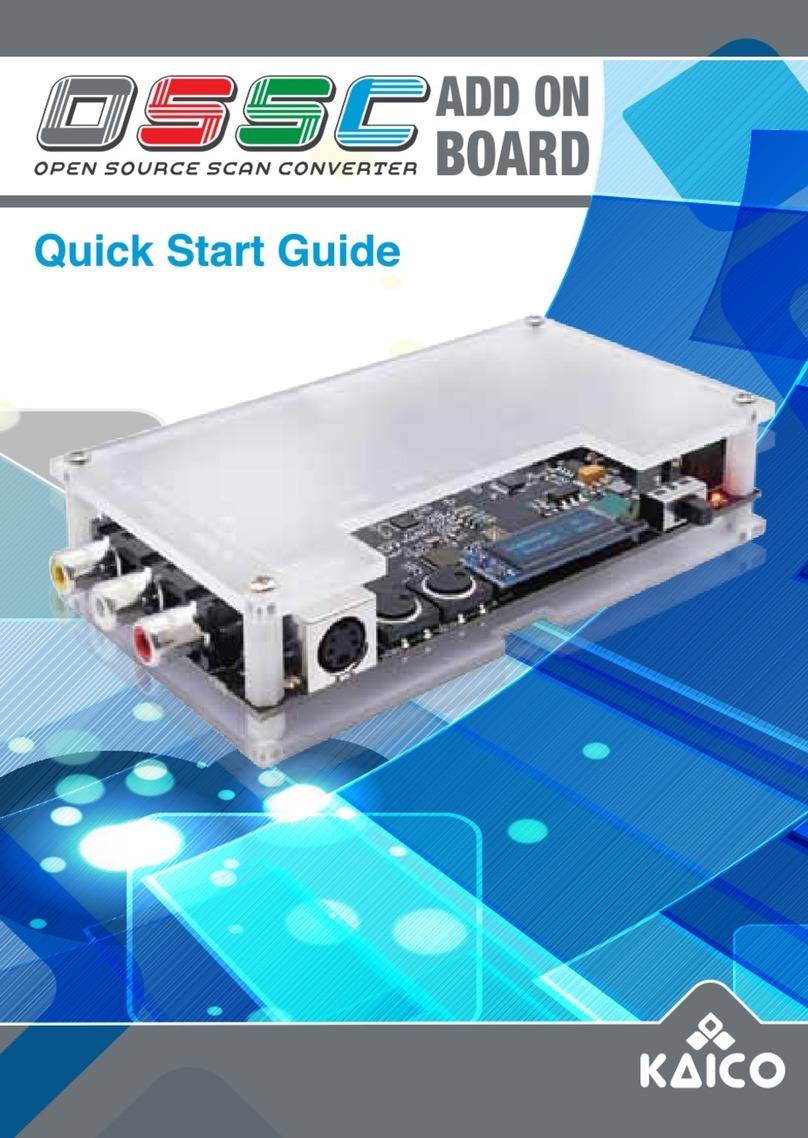
KAICO GBS C User manual

2
OVERVIEW 03
FEATURES 03
FUNCTION MODULE INTRODUCTION 04
OLED SCREEN MENU INTRODUCTION 08
WEB GUI INTRODUCTION 09
FIRMWARE UPDATES GUIDE 14
A triva true view based upscaler/video converter board
for retro gaming hardware

3
overview
GBS control is an improved GBS8200 RGB to VGA converter board, and an
alternative firmware for Tvia Trueview5725 based Upscaler / Video converter
board.
NOTE:
1) This device does not support composite and S-video inputs.
2) HDMI and VGA outputs will not work if connected at the same time. You will
only be allowed to have one connected at a time.
3) If you want to switch the video input signal (when you have more than one
input video source connected into this device), you need to power off the
device first to avoid potentially damaging the device.
FEATURES
1) Almost zero latency.
2) Supports most retro video game consoles.
3) Supports RGBS, RGSB, RGBS SCART, RGBHV, Component and VGA
Inputs.
4) Supports RGBS, VGA, Component and HDMI Outputs.
5) Supports high fidelity audio output.
6) Built in Si5351 stable clock generator.
7) Supports Video image adjustment.
8) Ability to balance the amplitude of the three primary colour signals - R, G, B.
9) Supports upscaling up to 1080p.
10) Supports downscaling to 240p/288p (Only through the Saturn AV
Connector).
11) No synchronization loss switching between 240p/480i, 480i/480p or
288p/576i.
12) Supported resolutions include:
(240p/288p/480i/480p/576i/576p/640p/720p/960p/1024p/1080i/1080p).
13) OLED Screen and WIFI web configuration pages help you make settings

4
FUNCTION MODULE INTRODUCTION
Tvia TruView 5275
RGB KNOB
2MB SD RAM
AUDIO OUTPUT
SCART INPUT
RGBS/YPBPR OUTPUT
(SATURN CONNECTOR)
COMPATIBILITY MODE
SLIDE SWITCH
POWER
SELF-LOCKING BUTTON
RGBS SYNC
SELF-LOCKING BUTTON
SYNC ON GREEN
SELF-LOCKING BUTTON
HDMI
SLIDE SWITCH
RGBHV/RGBS
SLIDE SWITCH
ON
OFF
RGBS INPUT COMPONENT INPUT
AUDIO INPUT
VGA INPUT
MICRO USB
DC 5V 2A
VGA OUTPUT
HDMI OUTPUT
MS9288A
LM1811MX
ROTARY ENCODER
OLED
ESP8266
CH340
Si53351 Clock Generator
PROGRAM POINTS
RGBS
RGBHV
MTV230MV
ON
OFF

5
MICRO USB:
The micro-USB port only supports firmware updates and does not supply
power to the device. If you need to update the firmware, please see the
“firmware update” guide on page 14.
RGBS SYNC SELF-LOCKING BUTTON:
When you press down the RGBS Sync Self-locking button the LM1881 chip
will “strip” the sync information from composite video. When the switch is not
pressed down it will bypass the composite signal.
SYNC ON GREEN SELF-LOCKING BUTTON:
When the SYNC ON GREEN BUTTON is pressed down, this device will
accept the VGA, RGBHV, RGSB signals. When the button is not pressed in,
this device will accept the RGBS and Component (YPbPr) signals.
NOTE:
When this button is pressed, this device can extract and use the sync on
green signal, so the RGsB signal (such as the progressive scan mode on
the retro game console) is accepted, but the “SYNC ON GREEN SELF-
LOCK¬ING BUTTON” and the “RGBS SYNC SELF-LOCKING BUTTON”
must be pressed simultaneously.
POWER SELF-LOCKING BUTTON:
When this button is pressed down, this device is POWERED ON.
DC 5V 2A:
Connect a suitable 5V2A, 2.1 x 5.5mm PSU.
HDMI OUTPUT:
Standard 3.5mm stereo headphone plug type connector. Outputs High-
Fidelity audio.
DC 5V 2A:
Outputs a HDMI Digital signal.
Tvia TruView 5275
RGB KNOB
2MB SD RAM
AUDIO OUTPUT
SCART INPUT
RGBS/YPBPR OUTPUT
(SATURN CONNECTOR)
COMPATIBILITY MODE
SLIDE SWITCH
POWER
SELF-LOCKING BUTTON
RGBS SYNC
SELF-LOCKING BUTTON
SYNC ON GREEN
SELF-LOCKING BUTTON
HDMI
SLIDE SWITCH
RGBHV/RGBS
SLIDE SWITCH
ON
OFF
RGBS INPUT COMPONENT INPUT
AUDIO INPUT
VGA INPUT
MICRO USB
DC 5V 2A
VGA OUTPUT
HDMI OUTPUT
MS9288A
LM1811MX
ROTARY ENCODER
OLED
ESP8266
CH340
Si53351 Clock Generator
PROGRAM POINTS
RGBS
RGBHV
MTV230MV
ON
OFF
RGBS/YPBPR OUTPUT (SATURN A/V CONNECTOR):
If you want to output RGBS (which you
must through the Saturn A/V connector),
you need to slide across the switch to
“RGBHV/RGBS SLIDE SWITCH”. If you
want Component signal output through
the Saturn A/V connector, you also
need to turn on the “RGBHV/Component
Toggle” in the web settings page.

6
NOTE:
1. The HDMI Slide Switch much be switched to off if you want to output
RGBS/Component signals through the Saturn AV Connector.
2. The GBSC only outputs lower resolutions such as 240p/288p through the
Saturn AV Connector.
VGA OUTPUT:
Standard D-Sub15 (VGA) connector.
NOTE:
If you want to output VGA signals through this interface, The “HDMI SLIDE
SWITCH” must be turned to “OFF”.
HDMI SLIDE SWITCH:
Toggles the HDMI signal OFF and ON.
RGBHV/RGBS SLIDE SWITCH:
If you want to output RGBS signal, please slide this switch to “RGBS” side. In
other cases, please keep RGBHV by default.
NOTE:
This function is used as RGBHV (VGA) to RGBS signal output.
SCART INPUT:
The European standard SCART interface can only receive RGBS signals.
The less common Japanese JP21 SCART must be used with a converter.
VGA INPUT:
Standard D-Sub15 (VGA) connector, accepts the VGA and RGBHV signals.
It can also receive RGsB signals.
NOTE:
If you use this interface, you must press down the switch ”SYNC ON GREEN
SELF-LOCKING BUTTON”.
COMPONENT INPUT:
Accepts the Component (YPBPR) signal.
NOTE:
The “SYNC ON GREEN SELF-LOCKING BUTTON” and “RGBS SYNC
SELF-LOCKING BUTTON” must stay pressed in.
AUDIO INPUT:
Left and right audio input.
182MM
105MM

7
RGBS INPUT:
Accepts the RGBS Signal. We recommend you press the “RGBS SYNC
SELF-LOCKING BUTTON” down to get a clean sync signal through the
LM1881 chip when using RGBS.
NOTE:
If you are using this input for a progressive scan RGBS signal (normally
480p or 576p), please press down these two switches at the same time. The
“RGBS SYNC SELF-LOCKING BUTTON” and “SYNC ON GREEN SELF-
LOCKING BUTTON”.
RGB KNOB:
Adjust the red, green and blue signals intensity of the output images.
COMPATIBILITY MODE SLIDE SWITCH:
Toggles compatibility mode ON and OFF.
NOTE:
The “Sega 32x/Neo Geo AES” consoles require the compatibility mode slide
switch to be turned ON. For best results restart the GBSC for the changes to
take effect.
182MM
105MM

8
OLED SCREEN MENU INTRODUCTION
OLED MENU
ROTARY ENCODER
Resolutions:
• 1920 X 1080
• 1280 x 1024
• 1920 x 720
• 1280 x 960
• Pass-through
• Downscale
• Back
Actions: Use the cotrol knob to switch menu items. Press down to confirm.
Presets:
• Preset Slot:1
• Preset Slot:2
• Preset Slot:3
• Preset Slot:4
• Preset Slot:5
• Preset Slot:6
• Preset Slot:7
• Preset Slot: Back
Misc:
• Restart GBSC
• Restore Factory
• Back
Current Settings:
• Output Resolutions
• Frequency
• Input single
1
1
2
2

9
WEB GUI INTRODUCTION
LOGIN TO THE WEB GUI:
STEP1: Search for WIFI through phone or PC.
WifiName: gbscontrol
Password: qqqqqqqq
STEP2: Enter IP (192.168.4.1) or URL (http://gbscontrol) in the browser
address bar and
STEP3: Click to enter the configuration page.
FIRST PAGE
1. Resolution:
• Your selection will also be used for startup.1280x960 is recommended for
NTSC sources. 1280x1024 for PAL.
• Use the “Matched Presets” option to switch between the two automatically
(Preferences tab).
• Choose an output resolution from these presets.
2. Presets:
• lf you want to save your customizations, first select a slot for your new
preset, then save to or load from that slot.
• Selecting a slot also makes it the new startup preset.
Login Page First Page

10
THIRD PAGE
1. Filters:
• Scanlines only work with 240p sources. They look best with the Line
Filter enabled.
• Peaking and Step Response are subtle sharpening filters and recommended.
SECOND PAGE
1. ADC Gain(Brightness):
• Gain +/- adjusts the gain for the currently loaded preset.
2. Picture Control:
• Adjust the screen position, scale and borders.
Second Page Third Page

11
FOURTH PAGE
SETTINGS
1. Matched Presets
• If enabled. default to 1280x960 for NTSC 60 and 1280x1024 for PAL 50
(does not apply for 720p/1080p presets).
2. Full Height:
• Some presets default to not using the entire vertical output resolution,
leaving some lines black.
• With Full Height enabled, these presets will instead scale to fill more of
the screen height. (This currently only affects 1920 x 1080).
THIRD PAGE
1. Filters:
• Scanlines only work with 240p sources. They look best with the Line
Filter enabled.
• Peaking and Step Response are subtle sharpening filters and recommended.

12
3. Low Res: Use Upscaling
• Low Resolution VGA input: Pass-through or Upscale.
• Low resolution sources can be passed through directly or you can choose
too upscale them.
• Upscaling may have some border / scaling issues but is more compatible
with displays.
4. RGBHV/Component Toggle
• The default output mode is RGBHV. This is suitable for use with VGA
cables or HDMI converters.
• An experimental YPbPr mode can also be selected - However,
compatibility is still not 100%.
5. Output Frame Rate: Force PAL 50Hz to 60Hz
• If your TV does not support 50Hz sources (displaying unknown format, no
matter the preset), try this option.
• If the frame rate is not smooth, please try reboot.
6. ADC calibration
• GBS Control calibrates the ADC offsets on startup.
• In case of color shift problems, try disabling this function.
7. Active Frame Time Lock
• This option keeps the input and output timings aligned, fixing the
horizontal tear line that can appear sometimes.
• Two methods are available. Try switching methods if your display goes
blank.
8. Deinterlace Method
• GBS Control detects interlaced content and automatically toggles
deinterlacing.
• Bob Method: Essentially no deinterlacing, no added lag but some
flickering.
• Motion Adaptive: Removes flicker, adds 1 frame of lag and shows some
artefacts in moving details.
• If possible, configure the source for progressive output. Otherwise, using
Motion Adaptive is recommended.
9. Developer Mode (For details, please visit the sixth page / page 13)
• Enables the developer menu which contains various debugging tools.
Note: Non-professionals do not set parameters at will.
10. Custom Slot Filters
• When enabled, saved slots will recover their own filter preferences.
• When disabled, saved slots will maintain current filter settings.

13
FIFTH PAGE
1. System
• Enable OTA (Over The Air)
• Restart GBS Control
• Initialize all settings of the GBS Control board
2. Backup:
Note: Intended for same device
• Backup / Restore of configuration files
• Backup is valid for current device only
3. WIFI:
• Search for nearby wireless networks. You can use GBSC Control to
access the Internet.
SIXTH PAGE
Developer
• To enter the developer page, please jump to the fourth page.
(settings) and turn on the Developer Mode.
Note: This page is a deep debugging mode for developers.
Please do not make changes if you are not a professional.
Fifth Page Sixth Page

14
FIRMWARE UPDATE GUIDE
STEP 1: Download the NodeMCU-pyFlasher
(https://github.com/marcelstoer/nodemcu-pyflasher/releases)
GBS Control Firmware
(https://github.com/RetroScaler/GBSC)
STEP 2: Open “nodemcu-PyFlasher”
14 Connect the GBS Control to your computer using the Micro-USB
cable. Select the proper COM port for your computer and choose
the latest GBS Control firmware.
STEP 3: Click “Flash NodeMCU”, then wait for the installation to complete.

15
NOTES:

16
2023-v1
Unit 14 Elgar Business Centre | Moseley Road | Hallow
Worcester | WR2 6NJ | United Kingdom
KAICO LABS
A triva true view based upscaler/video converter board
for retro gaming hardware

17
USER MANUAL
Unit 14 Elgar Business Centre | Moseley Road | Hallow
Worcester | WR2 6NJ | United Kingdom
KAICO LABS
A triva true view based upscaler/video converter board
for retro gaming hardware
Table of contents
Other KAICO Computer Hardware manuals