The QuickPan III / IV Family
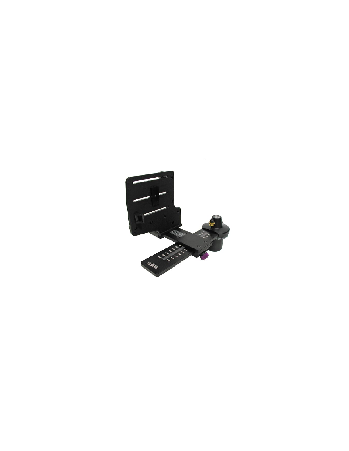
Twin-Axis Adapter
The Twin-Axis Adapter is designed to support most
digital and film cameras that are equipped with
fisheye lenses, or will appeal to those users who de-
sire two independent axes of adjustment. It can be
used with either the Standard Camera Bracket or
with the Compact Camera Bracket. The two axes
of adjustment positions the lens in such a manner
so as not to capture any more of the Rotator Base
than necessary. When a camera equipped with a
circular fisheye lens is installed on the bracket, only
a small segment of the Rotator Base will appear in
the image. This feature makes the Twin-Axis Adapter
ideal for those using iPIX software, Panoweaver and
other software applications that use circular fisheye
images. Both camera brackets support optional
Quick Release Camera Plates.
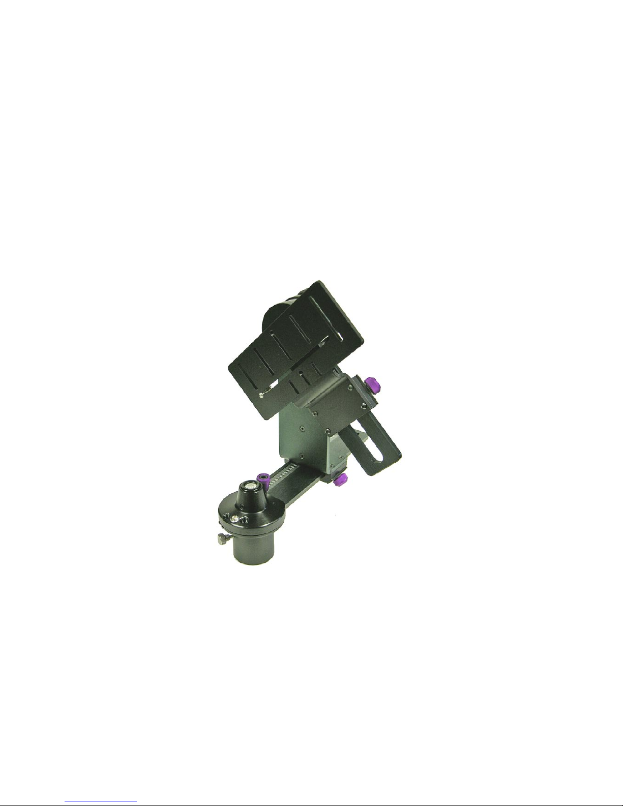
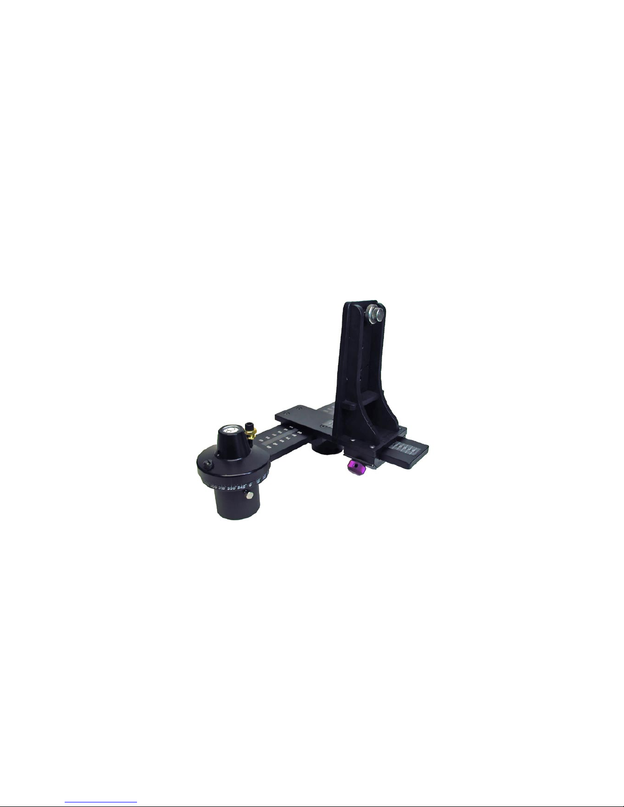
Spherical Camera Bracket
The Spherical Camera Bracket is designed to
support most digital and film cameras and to
permit the angular up/down elevation for the
capture of multirow spherical and QuickTime®
VR Cubic panoramas. This bracket is ideal for
those software applications that stitch multiple
rows of images, including up/down "cap" shots
such as REALVIZ Stitcher. The Spherical Camera
Bracket can also be positioned at a level zero
degrees, thus fulfilling the same functions as the
Standard Camera Bracket. You can also use the
Spherical Camera Bracket for shooting single-
row cylinders as well. An optional Arca-Quick
Release Camera Plate is also available.
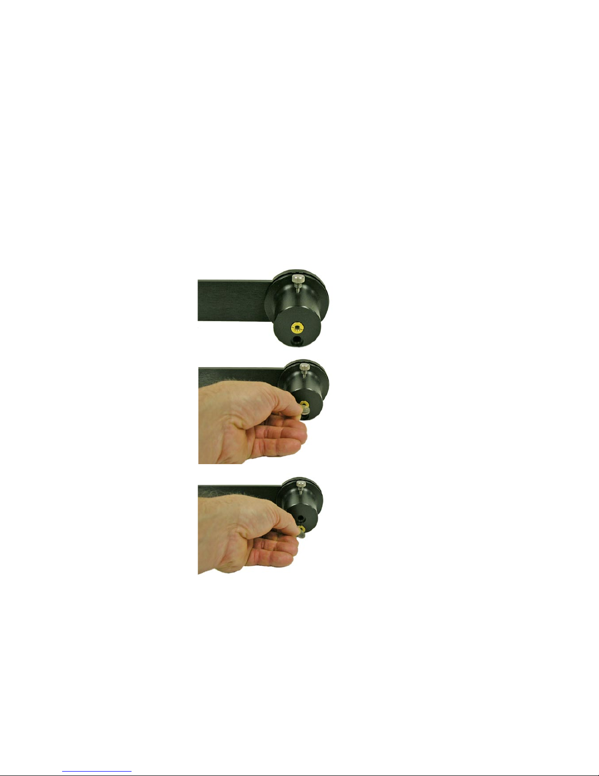
Standard Camera Bracket
The Standard Camera Bracket is designed
to support most digital and film cameras in a
portrait orientation. Used primarily to shoot
single-row cylindrical panoramas it is adjusted
along the horizontal arm to locate the camera
in the side-to-side orientation. There are three
slots in the bracket, that when used with various
positioning aids, provide the fore-aft adjustment
of the camera's nodal point, over the rotational
center of the tripod head. Earlier models used
an aluminum bracket while recent models use a
high-strength composite material (inset). A Quick
Release Plate is optional.
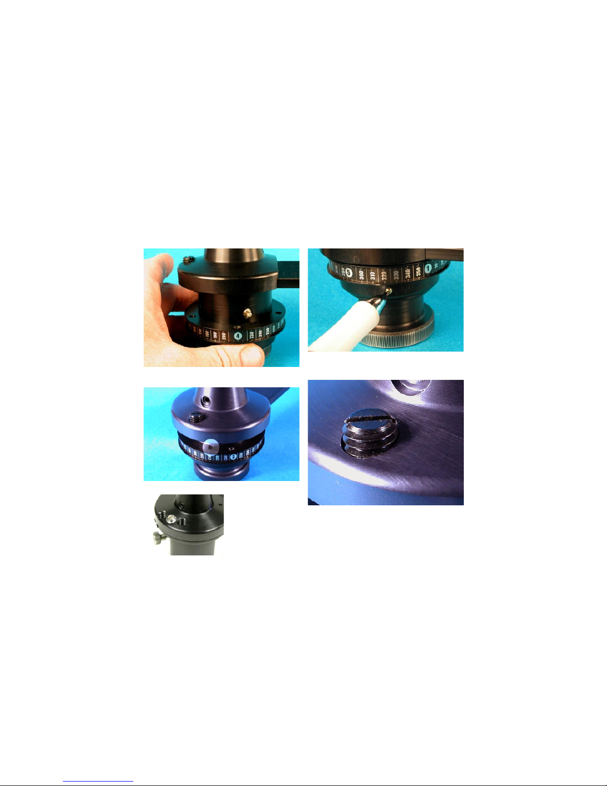
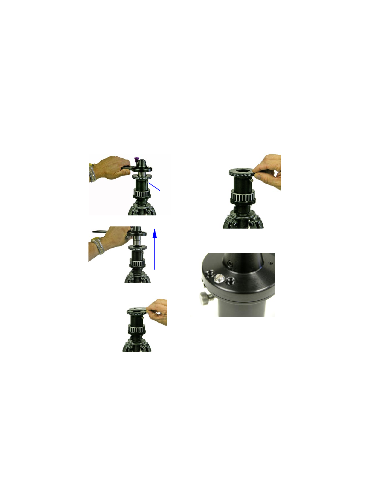
Rotator Base (QuickPan L, III & IV)
This heavy-duty design is lighter and more com-
pact than previous models and the competition.
The QuickPan bases employ interchangeable
indexing ClickDiscs or rings that support various
click-stop positions. These can be easily swapped
at any time and contribute to the light weight.
The indexing mechanism requires no lubrication
or adjustments and has no loose parts. The base
contains an integral circular bubble level and ac-
commodates either 1/4” or 3/8” tripod threads.
The latest QuickPan IV Rotator Base (Aug 04)
will also accept older Kaidan camera brackets
(i.e. KiWi+, QuickPan).
Introducing the QuickPan III / IV Components