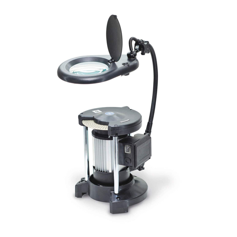
Kaindl BSG 20/2 User manual

OPERATION MANUAL FOR
DRILL GRINDING MAC INE
BSG 20/2
Original manual
Please keep for further use!
Kaindl-Schleiftechnik REILING Gmb , Remchinger Str. 4, D-75203 Königsbach-Stein, Germany
Tel.: +49 7232/4001 -0, Fax.: +49 7232/4001 -30, Internet: www.kaindl.de, E-Mail: info@kaindl.de

CONTENT
EC Declaration of conformity 3
Description 4
Directed use 4
Structure 5
Description of function 6
Technical data 6
Accessories 6
General safety advice 7
Taking care of the use 7
Basic safety precaution 7
Demand note for the operating staff 8
Safety icons 8
Moving to another place 8
Set up 8
Mounting and dressing the grinding wheel before first operation 9
Dressing of the grinding wheel 1 0
Change of the grinding wheel 11
Operation
Grinding of drills 1 2
Adjustment of top angle 1 2
Grinding of a twist drill 1 2
Grinding of a step-drill 1 3
Grinding of a sheet metal drill 1 4
Grinding of a wood drill 1 4
Grinding of a Forstner drill 1 4
Grinding of a milling cutter 1 4
Web thinning 1 5
Cross- or facette grinding 1 6
Spare part list 1 7
Maintence / Repairs 1 7
Warranty 1 8
2

EC DECLARATON OF CONFORMITY
The manufacturer: Kaindl-Schleiftechnik
Reiling Gmb
Remchinger Straße 4
75203 Königsbach-Stein
Germany
Declares that the machine
Grinding machine
described herein: Type:
BSG 20/2
Refers to the safety and health requirements EC-Machine instruction (2006/42/EC)
of the following EC instructions: EC-directive EMV (2004/1 08/EC)
Applied harmonised norms:
EN ISO 12100-1 and EN ISO 12100-2; EN ISO 13857; EN ISO 13732-1;
EN 61029-1; EN 60204 Part 1; EN 61000-6-1; EN 61000-6-2;
EN 61000-6-3; EN 61000-6-4
Changes in design, which affect the technical data, listed in this operation manual
and the directed use, therefore change the machine substancially, make this
declaration of conformity invalid!
The documents had been made up by: Reinhard Reiling
Kaindl-Schleiftechnik
Reiling Gmb
Remchinger Straße 4
75203 Königsbach-Stein
3

1 . DESCRIPTION
1 .1 DIRECTED USE
The
drill grinding machine BSG 20/2
is exclusively designed for occasional grinding of
twist drills, step-drills, wood-drills, Forstner drills, sheet metal drills and stone drills
(Carbide).
For other use, than listed here the machine is not destined for and is regarded as a
matter of adverse use!
The directed use includes also reading the operation manual, as well as keeping all
containing directions of use - expecially the safety information.
In case, the drill grinding machine BSG 20/2 is not used as per the intended purpose a
save operation cannot be granted.
For all personal- and material damages, arising by not intended use, not the
manufacturer but the user of the BSG 20/2 is reponsible!
4

1 . Grinding wheel cover, complete
2. Motor switch (left- or right-hand turn)
3. Motor 230 V 50 z single phase
4. Prism support with 2 boring for prism fixation
5. Knurled screw for prism fixation
6. Clamping lever for top angle adjustment
7. exagon screw for motor angle fixation
8. Knurled nut with scale for motor feed
9. Knurled nut with scale for drill feed
1 0. Reversing prism, clamping range from 2-20 mm
11 . Special corundum grinding wheel
1 2. Adjustable splash guard
1 3. Optical lens 5
4
3
6
1 2
9
1 0
1 3
11
2
1
7
2. STRUCTURE
5
8

3. DESCRIPTION OF FUNCTION
This mobile drill grinding machine made by Kaindl is unique as to its design and offers a
genuine alternative to bigger and considerably more costly equipments.
Owing to its solid construction, its high precission, its small space requirement and its
favorable price. The Kaindl drill grinding machine is an indispensable auxilliary equipment
and a real measure of economy, even for single operation sections and for smaller
craftmans workshop. This machine faciliates the adjustment and the resharpening of
twist drills to that extent, that everyone is able to resharpen drills with every lip angle that
is imaginable.
The prism reversing process automatically grants the highest precision and cutting edge
symmetry. The well planned conception and the possibility to easily replace all wear parts
make the Kaindl grinding machine BSG 20/2 to an indispensable auxiliary for many years
in your company.
6
4. TEC NICAL DATA
Dimension: L x W x 290 x 220 x 250 mm
Weight net: 1 3,5 Kg
Travel range: Motorslide: 55 mm
Travel range: prism feed: 45 mm
Electrical connection: Euro plug 230 Volt / 50 z; 1 20 Watt; 2800 RPM
Clamping range prism: 2,0 - 20,0 mm
Noise emission: < 70 dB(A)
Flow time of grinding wheel: around 1 0 seconds
5. ACCESSORY (OPTION)FOR BSG 20/2
1 6496 CBN Grinding wheel B 76 (1 25 x 20 x 20 mm)
1 7073 CBN Grinding wheel B 1 26 (1 25 x 20 x 20 mm)
1 0528 Magnetic depth stop for cutters
1 5422 Grinding wheel support for all grinding wheels
1 0530 Corundum grinding wheel fine grit 1 80, 1 25 x 20 x 20 mm
1 0532 Corundum grinding wheel 1 25 x 5 x 20 mm
1 0533 Corundum grinding wheel 1 25 x 1 0 x 20 mm
1 4580 Diamond grinding wheel 1 25 mm, covered on 3 sides, D 76/3 (carbide drills)
1 4581 Diamond grinding wheel 1 25 mm, covered on 3 sides, D 76/3
(carbide wood drills)
Technical changes may be done without notification!

7
Always wear
protection glases
when working with the
BSG 20/2!
Only operate the
BSG 20/2 with the
complete grinding
wheel protection!
Before changing the
grinding wheel or moving,
disconnect from electric
current!
6. GEMERAL SAFETY ADVICE
6.1 DUTY OF TAKING CARE BY USER
The drill grinding machine BSG 20/2 has been designed and constructed under
consideration of an endangerin analysis and carefull selectrion of observed harmonized
norms, as well as further specifications. The BSG 20/2 meets the state of the art and
grants a maximum of safety.
This safety can only be achieved in daily work, when all neccessary steps are taken. It is
the duty of taking care by user to control these steps.
The user has to take care that:
• Sound check, mounting and dressing of the wheel before the first start
(see page 9)
• the BSG 20/2 is used as directed (see chapter description)
• the BSG 20/2 is used in flawless workable condition, especially that the safety
installations are checked for function
• the requested personal equipment for the operator is availiable and will be used
• the operation manual of the BSG 20/2 is always kept in a readable conditions and
available near the machine
• the drill grinding machine BSG 20/2 is only operated by staff, who knows the
operation manual, especially the included safety information
• all safety and warning instructions are not removed from the machine and keps
readable.
6.2 BASIC SAFETY ADVICE

7. DEMANDS FOR T E OPERATING PERSONNEL
8
Only persons who are familiar with this manual are allowed to work with the machine.
8. EXPLANATION OF T E USED SAFETY ICONS
In this manual the following safety icons are used.
The reader should pay attention to these icons, shown here.
This icon points that there exists a danger
for life and health of persons.
Danger
This icon points that there exists a danger for
machines, material and environment.
Attention
9. MOVING TO ANOT ER PLACE
Only with disconnected plug!
Grap the drill grinder BSG 20/2 below the motor, between motor and
motor angle.
The drill grinding machine BSG 20/2 is made for placing on a worktable.
Take care for a solid stand on your worktable.
9.1 ENVIROMENMENTAL CONDITIONS FOR SET UP
Only in dry rooms.
Environmental temperature: from +5 to +50° Celsius
umidity: up to 90%, not condensing

After you have moved the machine to its final place of working, take the wheel and make
a sound check as well as a optical control of damage. Mount together the grinding wheel
with its support.
1 0. MOUNTING AND DRESSING OF T E GRINDING
W EEL BEFORE T E FIRST OPERATION
After you have mounted the grinding wheel support, place the wheel on the motor
spindle. (see page 11 "Change of grinding wheel")
After the grinding wheel is placed correctly on the motor spindle and the grinding wheel
cover is mounted, start dressing the grinding wheel first. (see page 1 0 "Dressing of the
grinding wheel")
Only after observing these steps, a save and correct opteration is possible!
9

11 . DRESSING OF T E GRINDING W EEL
1 0
For dressing of the grinding wheel, please release the clamping lever and place the prism
rest on the
150°
graduation line.
Fix the Kaindl diamond dresser device in the prism and fix the prism with the knurled
fixation screw in the buttom boring hole of the prism rest.
Move the motor feed with the knurled nut slowly towards the turning grinding wheel.
When the diamond pin touches the grinding wheel, then move the motor feed back and
furth. Do not feed more than
1-2 scale graduations
. For sheet metal drills, Forstner drills
or milling cutters, you need a grinding wheel of suitable shape.
By and adequate adjustment of the prism support, with the attached dresser, it is possible
to dress the wheel in any shape requested.

11
1 2. C ANGE OF T E GRINDING W EEL
Loosen both head cap nuts (1 +2) with a 1 0 mm engineers wrench and remove the
grinding wheel cover as shown on the picture.
Now open by use of an allen key SW 4,0 the screw in the center of the wheel support.
Now you can remove the grinding wheel from the motor spindle. Open the grinding wheel
support with the supplied key and change the grinding wheel.
When placing the support on the motor spindle, pay attention that the threaded pin is in
the notch of the motor spindle (picture 3). Now fix the screw in the center of the wheel
support with the allen key SW 4,0 and mount the grinding wheel cover in opposite
sequeence. Take care that the grinding wheel support is mounted correctly.
The grinding wheels have to correspont to norm
EN 12413
or
EN 13236
. After the
grinding wheel change make a 1 minute test turn. In case of uncommin performance,
switch off the machine and check for cause of failure.
The BSG 20/2 is not allowed to be operated without correctly mounted
grinding wheel cover!
For changing the grinding wheel, disconnect form electric current!
1
2
Pic 1 Pic 2
Pic 3

1 3. GRINDING OF DRILLS
PLACING AND ADJUSTMENT OF DRILLS
The reversing prism comprised a range of 2-20 mm. The
insertion and alignment of the drill is achieved in the most
simple manner conceivable. Open the prism by means of the
knurled head screw, provided for this purpose. Now insert the
drill to be ground inside the prism.
Keep the drill projecting about 1 5 - 20 mm beyond the prism
edge. The prism jaws are pressed together by a slight turn of
the knurled screw. The thus inserted drill is held tight in this
position, but it can still be turned easily as this is important for
the alignment. Now it is only neccessary to align the cutting
edge of the drill in parallel to the two indicated marks
(
Mark A
= right-hand drills;
Mark B
= left-hand drills).
The prism is to be tightened by hand only a hereafter, the
grinding operation can be started.
1 2
In order to work always in conformity with the properties of the material, you have the
opportunity no adjust every top angle that is imaginable.
The common top angle are 11 8°, 1 30° and 1 80° degrees.
The angles are solidly marked on the prism slide. They can easily adjusted by opening
the clamping lever (see picture on page 5, No. 6) and by moving the prism rest.
1 4. ADJUSTMENT OF T E TOP ANGLE
Deviating from this basic adjustment, you can change your relief angle depending on the
material to be drilled.
You want a higher clearance angle - a higher cutting capacity, then revolve the drill
slightly to the left (shorter graduation mark on the prism). If you want less relief - a lower
cutting capacity, then revolve the drill slightly to the right (longer graduation mark on the
drill). You will thus obtain the correct cutting edge and angle for every kind of material.
In case of a broken drill, having no cutting edge for adjustment, grind the drill to get a
truncated end. Align the cutting corners as closely as possible to the adjustment marks
and regrind the drill until a new cutting edge apears. Thereafter the adjustment is to be
carried out as before.
B
B
A

1 5. GRINDING OF T E DRILLS
1 3
The prism, with the well aligned drill is slipped on to the prism swing pin and revolved in
front of the grinding wheel (page 5, No. 4). Simultaniously move the drill feed carriage
towards the grinding wheel by means of the knurled nut (page 5, No. 9) until one side of
the prism is well formed.
Note the scale mark on the nut (e. g. scale mark 5). Move backward the feed carriage by
2 to 3 scale marks closer to the grinding wheel.
The drill in this position is swiveled until no further formation of the sparks are visisble.
In the order to achieve the best possible cutting edge symmetry, the prism is reversed
again by 1 80° without any alteration of the position of the drill feed carriage. The other
side is ground until no more spark are visisble.
ATTENTION!
In order to prevent temper of anneal, please always work with low
feeding grade.
Wear your safety glasses!
Grind the cutting edges of the first step same as standard
twist drills. The cutting edges of the second step are
likewise aligned in parallel with the indicated marks of
adjustment (see chapter "Alignment and adjustment of
drills"). The drill inside the prism is then pushed forward
until the second step passes by the grinding wheel and
touches the grinding wheel (Picture).
Using the knurled nuts (7) and (9) you can do the fine
adjustment of the drill to the grinding wheel. Thereafter
you resharpen the cutting edges by way of the reversal of
the prism as described before for standard twist drills.
1 6. STEP DRILLS

1 7. S EET METAL DRILLS,WOOD DRILLS,
FORSTNER DRILLS AND CUTTERS
For the above mentioned drills it is recommended to use specially dressed grind wheel
faces (Picture).
Release the clamping lever of the prism rest and place on the adjustment line of the drill
feed carriage (see picture). The adjustment of the drills is identical to twist drills. The fine
adjustment of the drill to the grinding wheel is carried out with the screws
(Pic page 5, No. 7 and 9).
Only when the setting-up work has been completed, switch on the motor and start
working ad described in the chapter "Grinding of drills". For milling cutters. the prism is
fixed with the knurled screw in the lower screw hole, placed on the side of the prism
support. (Page 5, No. 5).
By moving forward with the knurled nut, sharpen one cutter and after reversal of the
prism, sharpen the second side (Pic page 5, No. 9). For milling cutters having 3 or 4
cutting edges you will need the magnetic deph stop (option).
Forstner drills in contrary to other drills are not adjusted accourding to adjustment marks
on the prism, but aligned to the stagnant grinding wheel.
The grinding operation is same as for cutters.
1 4

1 8. WEB T INNING
1 5
With the new clamping prism it is now possible to thin the web of
the sharpened drill.
1 . The boring holes
A
and
B
are for grinding of cutters and
drills with 4 facet shape.
2. The boring
C
is for web thinning.
For web thinning let project the drill 25 mm outside the prism and
do not change the possition of the drill in the prism. Fix the prism
with the knurled screw in hole
C
.
Use the upper boring on the prism support. Loosen the clamping
lever and move the prism support to
90°
.
By use of the prism- and motor feed, thin the web of the drill by using the left edge of the
grinding wheel.
After one side is finished, nore the graduation marks on the prism feed screw and move
back for one turn. Now reverse the prism for
180°
, fix again in hole
C
and move forward
with the prism feed to the same graduation mark on the knurled screw.
Prism support
90°
Fixation screw
Clamping lever
AB
C
AB
C

1 9. CROSS-OR FACETTE GRINDING
After the sharpening procedure, you have the possibility to change the standard twist drill
shape to a cross- or facette grinding.
The twist drill remains in the prism clamp without any changes in setting. Fix the prism
with the fixation screw M4 in hole C (see page 1 5). Open the clamping lever and turn the
prism support to 1 50°.
Move with the motor feed to the left, till you touch the cross cutting edge of the twist drill
by the right edge of the grinding wheel.
Dive slowly into the center of the cross cutting edge by moving forward the prism feed.
Notice the position on the feeding scale, move back, loosen the fixation screw, reverse
the prism for 1 80°. Fix the screw again and move slowly forward again to the same
position.
1 50°
Fixation
screw M4
Clamping lever
1 6

1 7
Item No. Description
11 303 Prism 2 - 20 mm
1 7840 Prism support
1 0546 Clamping lever M8 with washer for prism support
1 6556 Fixation screw for prism to prism support
1 0554 Pin 7 mm for prism support
1 0888 Dresser unit without diamond
1 0550 Spare diamond for dresser unit
1 0556 Scale-ring for the drill feed
1 0557 Scale-ring for the motor feed
1 0563 Grinding wheel cover, painted
1 0565 Motor 230 Volt / 50 z, 2800 RPM; painted
1 0567 Cover for fan propeller
1 0568 Fan propeller
1 0570 Motor switch
1 0571 Box for motor switch without switch
1 5422 Grinding wheel support complete without grinding wheel
Only use original Kaindl spare parts!
20. SPARE PART LIST
21 . MAINTENANCE
The drill grinder BSG 20/2 should be cleaned from grinding dust with a soft brush.
Persistant dirt, please clean with usual in trade machine cleaner. After cleaning, please
grease all movable parts with some drops of machine oil. To prevent erosion of the blank
parts, also grease with little oil and rug with a soft rag.
22. REPAIRS
All parts listed in the spare part list can be replaced by the user. Repairs of assembly
groups as reversing prism of the base plate with guide and spindle can only be repaired
in our company, as thesed parts are mainly reponsible for the precision BSG 20/2 .

The warranty is
12 month
and refers to
one shift work
on condition of an appropriate
use. The warranty comprises the costs for replacement of defect parts and assembly
groups including the neccessary working time (the replaced parts can also be overhauled
parts or assembly groups).
Excluded from any warranty are:
• Wear parts due to operating conditions
• Transport damage
• Inappropriate use of the machine
• Damages by use of force
• Damages and consequential damages by violation of duty for taking care by the
user.
In case of a warranty claim, we please ask you to form us about the serial No. of
your machine!
Return have to be authorized by us before back-shipment. We reserve the right to charge
you with the shipping costs, in case the return was not authorized.
23. WARRANTY
1 8
Table of contents
Other Kaindl Grinder manuals