Kaise SK-7720 User manual

KA:SE CORPORバ T:ON
422 0aza Hayashlnogo,Ueda City, Nagano Pref,386‑01 」ap(tl,
TELEPHONE:UEDA(0268)35‑1600(REP)
TELEX:3327409 KAISE」
FAX:(0268)35‑1603
Printed in」 apan 0792
==■=========¨ =帝==¨==¨ ==="===== =
=
aise ‡
"
=
¨
INSTRUC丁10N MANUAL‡
¨
=
¨
=
=
■
MODEL SK¨ 7720 ‡
SK‑7722 ‡
‡
=
日
創
丁AЛ ttMttER I
=
¨
"
=
=
=
¨
KAISE CORPORAT:ON ‡
"
=
=
=
●
====¨ ="¨ =====■ ===========¨ ===

CONTENTS
page
l :NTRODuC■10N …
…
…
……………
…
…………
……
…
2
2 SPECiFiCAT10NS… ……
…
…
……
……
…
…
…
……
…
…
3
2 1 SPECIFICAT:ONS of MODEL SK‑7720 ‑― ―――――¨
―
…
…
3
2‐2 SPECIFiCAT10NS of MODEL SK‑7722 …
…
…
…
……
5
2‑3 GENERAL SPECIFICAT10NS …
…
…… ………
…
…
7
3 SAFETY PRECAUT10NS ………
…
…
…………
…
…
…
9
4 NAME:LLuSTRAT:ON ¨¨¨ ¨…
…
……
…
……………
…
…10
5 MEASuREMENT PROCEDURE ―――
¨¨¨ ……
…
……
…18
51 PREPARAT10N FOR USE …
…
…
…
……
……
…
…
…
…
18
5‐2 A+V(DC CURRENT AND DC VOLTAGE)MEASUREMENTS 19
5‑3 A十 日z(AC CURRENT AND FREQUENCY)MEASuREMENTS 21
5´ V+HZ(AC VOLTAGE AND FREQUENCY)MEASUREヽ 4ENTS 21
5う 0(RESISTANCE)MEASUREMENTS …
…
…
…
…
………
……
22
5 ℃(TEMPERATURE)MEASUREMENTS ――
………
…
…
…23
57 COMMENTS on True RMS MEASUREMENTS ――
―――
――…
23
6 MAINTENANCE ……………
………
……
…
……
…
…
…
25
6■ VVARRANTY STATEMENT …
…
…
…
………
…
…
…
……
…
25
6‑2 BATTERY REPLACEMENT ……
…
………
…
…
25
6‐3 CALIBRAT10N ―
―
――
…
………
…
…
……
――
¨
―
……
…
25
6´ REPA:R ―
…………
…
……
…
…
…
………
…
……
…
…
25

A GENERAL
The modes SK‑7720'7722 are qu te a new type Of D g tal Clamp lleters which
can measure d fferent 2 elelnents at a time and display them o∩ a b19ger Dual
Display LCEl ・
A・ hen measur ng current, simply clamp On the conductor to be
tested vvth the Clamp head Both the models are very useful and versatle
clamp meters designed fOr test ng and maintaining mu tfar ous electr cl
eloctronic app anceS. equipments and fac‖ ties and also designed A th
feasib ty in mind for checking electr c systems of lη oto「 cars
B FEATURES
l WIDE RANGING:1000A ACIDC and 650V ACIDC(SK‑7720)or 250V ACIDC
(SK‑7722) Frequency, Resistance, Temperature l.leasurements are
ava able
2 4000 COUNT AND DUAL DISPLAY LCD:Un t and vanOus s19ns are ShOWn
3 TRUE RMS MEASuREMENTS:Measurements can be lnade accurately by
True Rms fOr AC vo tage and current even if the signals a「 e dissimlar to
4 FREOuENCY ,DUTY CYCLE ・PULSE VVIDTH MEASUREMENTS: Very
useful for cheCking cOntro‖ ing systems of mdorcars as、 ve‖ as apparatus
and equipments
5 DISPLAY HOLD, PEAK'MAX,MIN and DIFFERENCE MEASuREMENTS:
Each funct on works simutaneously on 2 chan]els l.laxlヽ Иin values are
shown in 4 combinatons
6 DuST― PR00F AND WATER― RESISTANT CASES:The frst clamp meters in
the wond that prOv ded DUST― PR00F and MIATER― RESISTANT cases lnade
of h gh he.‐ t res stant ABS
7 SAFETY DESIGN:SK‑7720 has been designed accordin9 to lEC Publca―
tons 348
2‐l SPECiF:CAT:ONS OF MODEL SK‐ 7720
A+V(DC CURRENT+DC VOLTAGE)
Range Resolut on Accuracy lnput
A
4000A 01A ■15%rdg± 309t
1000A(400‐´
600A)
(601‐ 1000A) lA ±150/Ordg± ldgi
±
30/1『 dg± 3dOt
V4000V 100mV ■
100/。 rdg■ 3d9t
ll o2/・ rd9=l dgt
approx
2MniV
・
Samp ng rate is 375 tmes/sec ln ordinary mode, but 15 t mesノ sec in
PEAK/ヽИA× /111N VALUEヽИEASUREMENTS and± 100/Drdg± 3d9t s addedto
the above accuracy
・Ove‖ oad Protect on i A range 1500A DC for one minute(600V line)
V range 1000V DC For one mi∩ ute
A+Hz(AC CURRENT+FREQUENCY/DUTY CYCLEノ PULSE WIDTH)
・Crest Factor i less than 3
・Over oad Protect on l1500A rms for one minute(600V lne)
1100A
600V Ine
True RMS(AC coupled)
±150/Ordg=3dgt
Range Resolution Accuracy Gate Time lnput
Sensl vity
Hz 10 0H l° °DHz
95Hz‐ 4000Hz
0Hz l± 050/Ordg■ l dgt ≦0 1sec 5A
IS neWave)
10A
(S neWave)
Hz ‐
±05●10rd9■ l dgt lsec
Duty Cyc e , 000/1〜 9990/1 0●
/O I ±30/lrdg± 3d91
Pulse Width 11 0mS‐ 999 9mS 0lmS I=051/Ord9=3dgt

True Rl■ lS(AC Coupled)
Range Resolut on Accuracy
661芝〜66Hz丁 40Hz‑400Hz lnput
Resistance
Max input
Voltage
V4000V
650V
100mV ±io%rdg± 3dgi ±15%ぬ 0± 3dOt Approx
2MO 700V rms
lV
V+Hz(AC VOLTACE+FREQUENCY/DUTY CYCLE/PULSE WIDTH)
・Crest Factor i less than 3
・0∨e‖ oad Proteclon:1000V rms for one m nute
2‐2 SPECIFICAT10NS OF MODEL SK‐7722
A+V(DC CURRENT+DC VOLTAGE)
・Samp ng rate is 3 75 t meS/sec in ordinary mode, but 15 i meS/sec in
PEAK/MAX/MIN VALUE MEASUREMENTS and±1007● rdg± 3dgt s added to
the above accuracy
Ove‖ oad Protect on:A range 1500A DC For one minute(600V line)
V range 400V DC for one minute
λ+Hz(AC CURRENT+FREQUENCY/DUTY CYCLE/PULSE WiDTH)
True RllS(AC coupled)
Resolut on
OveHoad Protect on i 400V rms for one minute
C(TEMPERATURE)
・The above accuracy,s that of DCヽ Иonly ν′
hen measur ng,the accuracy of
Temperature Probe musi be added
・Ove‖oad Protect on i 400V rms for one minute
01A
ovenOad PrOtect on:1500A rms for one minute(600V line)
Range Resolution Accuracy lnput
Resistance
Max lnput
Current/Vo tage
A
V
4000A 01A ±150/OrdO■ 3dgt 1100A
600V Ilne
1000A (400‑600A)
(601〜 1000A) lA ±15%rd9=l d9t
■30/Ordg± 3dgt
4000V 10mV =10%rd9■ 30gt Approx
2MΩ 300V
2500V 100mV ±10●/。 rdg± l dgt
ResOlution Accuracy Gate Time lnput
sensnivity
10 0Hz‐ 100 0Hz 01Hz ±050/●rd9± イ
dgi く0 1sec 10V
(S neWave)
95Hz〜 4000Hz lsec
Duty Cycle
Pulse VVidth
00%‐ 9990/● 01% ■30/Ordg± 3dgt 30V
(S neWave)
10mS‐ 999 9mS 01mS ±05%rdg=3dgt
Ω(RESISTANCE)
50HzたもoH芝 140H2〜400Hz l
A '1000A (400‐ 600A)
│型 剋
・Crest Factor: less than 3
Range
Range
iO OHZ〜 100 0Hz
Resolution Accuracy Gate Time
く
0 1sec
Input
Sensitiv ty
01Hz 十o5%rdO‑ldgi 5A
(S neWave)
95Hz‐ 4000Hz lsec
Duty cyc e 000/●〜9991/O 0100 3●/.rdg‑3dgi 10A
(S neWave)
Pu:se ヽVidth 10mS‐‐
999 9mS1 01mS ■05●/Or"■ 3d9t

True RMS(AC Coupled)
Range Resolution Accuracy lnput
Resistance
Max lnput
Voltage
50Hz^Ψ 60Hz 40Hz^‐ 400Hz
V4000V 10mV
=10%rdg± 30gt ■15%rd9■ 3d9t Approx
2MΩ 300V rms
2500V 100mV
V+Hz(AC VOLTAGE+FREQUENCY/DUTY CYCLE/PULSE WIDTH)
・Crest FaDlor:less than 3
・ Ove‖ oad Protect on:400V rms for one minute
・ Ove‖oad Protect on:A range 400V rms for one minute
C(TEMPERATURE)
・The above accuracy is that of DCl.l only VVhen reasurng,the accuracy Of
Temperature P「 obe must be added
・OveJoad Protect on l●00V rms for one minute
・V′ hen F「equency is bet.teen 40Hz and 400Hz(eXCept 50Hz to 60Hz)on
1000A AC or 250V AC range,1 000rdg± 3dgt must be added to the above
accuracy
2‐ 3.GENERAL SPECIFICAT10NS
l DISPLAY:
a Numerical Display,Dual D splay 4000 Count LCD,lvlax 9999
b unit and signs:
Channe l ―
mV,V,mA,A,Ω ,kΩ ,℃ ,BAT,AUTO,DH,D FF,REC,
P,MAX,MN,一 ,一 ,〜
Channe 2 ‑ mV,V,Hz,mS,OO,DIFF,REC,MAX,MIN,一,一 ,^´
2 0PERATING PRINCIPLE:Dual SIope lntegrat on
3 RANGE SELECT10N:Autorang ng'AUTO・ s gn shows
4 SAMPLING RATE:15 times/sec(each channeD But,3 75 times/sec for A
+V measurement n ord nary mode
5 POLARITY:AutopOla ty,'一
・sign When minus
6 0VERLOAD lNDICAT!ON:'OL'sgn b nks
7 BATTERY WARNING:"BAT'sign shows
8 DISPLAY HOLD(DH):Data are held by DH Key and'DH・ s19n shows
9 PEAK/MAX/MIN VALUE MEASuREMENTS(REC):l.lax/Min readings on
tvvo Channels Peak/ヽ Иax/ヽИin readings are
ava‖ able for A + V measurements
10 DIFFERENCE MEASUREMENTS(DIFF):Des red value being measured is
converted to read zero on LCD and only d fference
is sho.n、 v th proceeding measurements DIFF sign
shovvs
ll DUTY CYCLE(DuTY》 VVhen measunng A or V and Frequency(H2)S
sho、vn,frst press of DUTY Key shOws Duty Cycle
(° o)Second press shows Pulse ν′dth(mS)in High
LeVet th rd press shows Pulse
・
idth(mS)in LOW
ANALOC OuTPuT
Outptlt Voltage Accuracy Output
Reslstance
DC 1000A DC lV is 0〜600A:=25● Ordg± 2mV
Approx 200 0
6Cl‐ 1000A l± 40%rdg± 2mV
DC 250V DC 25Vfs =20%rdO± 2 5mV
AC 1000A
(50‑60Hz) AC lV fs 0〜600A:± 30%rdg± 2mV
60〜1000A:± 50%rdO=2mV
AC 250V
(50‑60Hz〕 AC 25Vis =25● Ord9± 2mV
Range Resolution Accuracy Gate Time lnput
sensn vity
10 0Hz‐ ‐
100 0HZ 01Hz
=05%rdg■ l dgi
く0 1sec 3V
(S neWave)
95Hz‐ 4000Hz lHz lsec
Duty Cycle 00%〜 99 90rO 01% ±3%rdg± 3dgt 5V
(S neWave)
Pulse Width 10mS‑999 9mS 01mS
0 (RESlSTANCE)
Range Resolution Accuracy Measuring
Current Open
Circuit Voltage
4000Ω 10 +10%rdg± 3dgt Approx olmA ≦5V
20 00k Ω 10Ω +10%rdg± l dgt
Range Resolution Accuracy
‑30C‐ 150C lC +10。 rdg± 3dgi

Level and fourth press returns to Frequency(HZ)
measurements
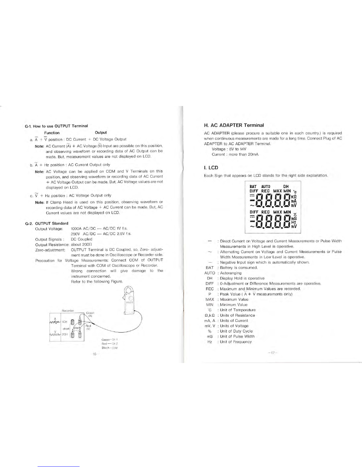
12 0UTPUT TERMINAL(SK‐ 7722 oniy)
VVhen measunng A + V,A + Hz or V + Hz,Output Terminal can be
connected to OscHloscope or Recorder to observe.vaveform or record
the data
Stereo Min 」ack(35mm φ
)s used for ouTPUT Term nal
Output Vo ta9eii000A AC/DC ―AC/DC lV fs
250V AC/DC ―AC/DC 25V fs
Output Resistancei approx 2000
0utput Accuracy,DC O‑600Ai ±25%rd9=2mV
DC O^‐ 250Vi ■200/Ordg± 25mV
13 0VERLOAD PROTECT10N:
a A,1500A AC/DC for one minute 600V line
b ViSK‑7720:1000V rms AC/DC ror one minute
SK‑7722, 400V rmS AC/DC for one minute
c Ω/・ C i400V rms ACノ DC For one minute
14 DIELECTRIC STRENGTH:
SK‑7720 1 4kV AC forl minute(beヽ Veen the case and the Terminals)
according to lEC Publcatons 348
SK‑7722 1 2 2kV AC forl minute(betVVeen the case and the Terminals)
and does not accord to lEC Pub catons
15 MAXIMUM VOLTAGE OF CURRENT LINE:600V AC/DC
16 0PERATING TEMPERATURE&HUMIDITY;OC‑40 C leSs than 800も RH
In non― condenslng
17 STORACE TEMPERATURE&HUMlDITY: ‑20C‑260 C esS than 701/O
RH in non― condensing
18 POWER SuPPLY:One 9V 6F22(S‑006P or NEDA 1604)battery or AC
Adapte「 (proCure in each country)
19 BATTERY L:FE:25 hour cont nuous operation
20 CONDuCTOR DIAMETER:Max 36mm ψ
21 D!MENS10NS&WVEIGHT:200× 64X33 mm,310g
22 ACCESSORIES:One pat Test Leads(100‑321 0ne 9V BatteⅣ 6F22(S―
006P),986 Carrying Case lnstruct on ヽИanual
23 0PT10NAL ACCESSORIES:818 Temperature Probe(Sheath type), 880
Line Separator, 922 1nput Cord ior Battery
Power 923 1nput Cord for AC Adapter.930
0utput Cord for Recorder,940A‖ igator clps
Correct knovv edge about electric lmeasuremenis is necessary since electr c
measurement is somet mes a very dangerous vVOrk To elminate possib‖ ty Of
iniury to operator and damage to the instrument and equipment,the fo‖ ovv ncJ
precaut ons and measurement procedures are recommended ヽИis― use,abuse
and carelessness cannot be prevented by any vvrtten vVord and is fu‖ y the
operator s responsib‖ ilv Observing the fo‖ o、ving precaut ons, take saFe
measurements
l Do NOT attempt to take any measurement of vo tage or current higher than
the maximum range of the funct on on this instrument
2 The instrument perorms PolilER‑ON lNITIALIZE automatca y w th
POV′ER/FUNCT10N S、 vtch set to des red postion INITIALIZE cannot be
performed exact y f any value ofinputis being app ed to the instrument Do
nOtra tO set POVVER/FUNCT10N Svvich to des red pos tion vvth∩ o input
value bein9 app ed For deta‖ s, refer to page 18
3 Do NOT change POVVER/FUNCT10N S ttch..th Test Leads connected to
the c rcut to be measured
4 Acquaint yourse f vvth the localoo of high vo tage in the equipment under
test orin the c rcu t to be measured f there is solndhing vvrong vvth the
equipment o「 the c rcut, いigh vo tage leaKs irom unexpected locat ons
which may cause the eleCtr c shOCk accidents
5 1・ hen making neasurements,take safety distance from the power supply or
the c rcu t tO prevent any part of your body r「 Om tOuChing high vO tage
6 Do NOT fa‖ to confrm before eveⅣ measurement that the body of this
instrument and the handle insulatorS Of the Test Leads attached to the
instrulnent have no cracks nor any Other damage on it ヽИake sure that the
body and the handle insulators are free of dust,grease and moisture
7 Keep the instrument a、 vay from strong noise、 vhich may somet mes catSe
random display or measurement error
8 Thsinstrument s NOT APPROVED:or use in explos ve atmosphere vapor
or dust

」CLAMP HEAD
A PO`″ER/FUNCT10N
swnch
C REC Key
REC Key operaos in two modes n the nrst mode,Max mum and M nimum
Values are shown on LCD as C l Flow Chan But,in Resistance or Temperature
Measurements,MaX mum and M nimum Va ues are shown on CHl on■
ln the second mode,Peak Value of DC current can be measured in A+V
measurements Peak,ヽИax mum and Minimum Values are shown on LCD as C―
2 F ow Chart
C‐ l CHl MAX/MIN+CH2 MAX/MIN MEASUREMENT MODE
Press REC Key(.・ 7thin one second)10 enter this mode
REC Key
B DH key
G OUTPUT Terminal
frst press of REC Key
E DUTY Key
H AC ADAPTER
Term na
A POWER/FUNCT10N Swnch
Povver and Functions are selected e¨ ‖
y by a single― deck ROTARY Svtch
Set POVVER/FUNCT10N Sw tch to des red pOs tion
Do NOT Fa‖ to set this Sw ich io OFF pOs tiOn after measurementR
B DH Key
Press DH Keyto hold d splays Of bOth CHl and CH2 on LCD DH sign is shown
ヽ
″hen measunng OHM Or c,the d splay oF CHl s held on y
To cancelthis Key, press it again and DH sign disappears
NOTE:νVhen DH Key s operatng,REC Key,DIFF Key and DUTY Key do not
WOrk(But,REC Key works to make lvlax/ヽ Иn value display f REC Key
is pressed before DH Key is pressed)
MAX/MIN Measurements stan
CHl ―
REC sign and measuremeni value are shown
CH2 REC sign and measurement value are shown
seventh press
second press
MAX'M N Measurements 9o
CHl― ―
REC,MAX signs and Max mum Value are shown
CH2 ‑ REC,MAX s19ns and lvlax mum Value are shown
th rd press
MAX,MIN Meぉ urements go
CHl ―
REC,l.lAX signs and Max mum Value are shown
CH2 REC,MN and M nimum Value are shown
fourth press
MAX/M N Measurements go
CHl REC.lvl N signs andヽИinimum Value are shown
CH2 ‑ REC,MAX and ヽИaximum Value are shovvn
ffth press
MAX/MIN Measurements go
CHl ―
REC,ヽИN signs and l.linimum Value are shown
and Min mum Va ue are shown
D DIFF Key
FRONT Case
REAR Case F INPUT Terminals
sixth press
MAX/MIN Me urements gO
CHl REC sign and present measurement value are sho,Vn
―return tO stage 2
10‑
measurement value are shovvn

C‐ 2 CHl PEAK+CH2 MAX/MIN MEASuREMENT MODE
un A+V Measurement on y)
Press REC Key(fOr two seconds)tO enter this mode
O IoⅢⅢ,ry MeaSU,PTも │
f rst press(fOr 2 seconds)of REC Key
PEAK,MAX/M N Measurements 9o l
CHl …REC,P signs and Peak Value are shown i
LgFi■ittFC,1咀 and Pea,P19Te,lY旱 Ⅲ9翌ЮS堕些□
second press
CHl REC P signs and Peak Value are sho vn
CH2 REC,Mn and M nimum Va ue are shown
fourih press
PEAK MAX,MIN Measurements go
CHl― REC,P signs and Peak Value are sho、 vn
CH2 ‑ REC sign and present measurement value are shovvn
return tO stage 2
Note:To make Battery Test when starting engine Of automoble,
enterthis mode C‑2 and select・ 3 CHl REC P i CH2 REC
ヽИIN' Peak Current andヽ Иininum Vo tage Of battery can be
measured
C‑5 DIFF Key operation
DIFF Key can nOt Operate vvhen REC Key is operat ng
V′ h e REC Key can Operate and PEAKllvlAXIヽ И
INヽИeaSurements are avanable
when DIFF Key s Operatng
D D:FF Key
DIFF Key proVides Zero Adlustment as vve‖ as D ffere∩ ceヽИeasurements
DIFF Key vvorks on 2 channeis at a time But,、 vhen meaSur n9 Resistance Or
Temperature t WOrks on CHi only
D‐ l ZERO‐Adiustment
The instrument performs POWER‑ON llllTIALIZE automaiCa‖ y wnh Po,vERI
FUNCT10N Sw ich setto desred poston
flNITIALIZE is periormed exacty LCD wi‖ d splay O■ l dig t
But, somet meS LCD displays 3‑4 digts due to feSidual magnetsm On the
clamp head ln thls case,clck CLAMP HEAD s ghty severaltimes
lf oot yet efFeCt ve,press DIFF Key,and LCD wll display 0 1l dig t with DIFF
sign shovvn
NOTE:Genera‖ y, stan measurements to see O'l d19t on LCD But, the
spec fied accuracy iS ensured even if measurement are made vvth 3 10
4 dig is rennained
D‐ 2 Difference Measurements
When lneasur ng a des red value or applyin9 a des red value on the instrument
press DIFF Key and the des red value is stored and converted to display zero
plus or lninus one di9t on LCD DIFF si9n appears On LCD The d fference
betvveen measurng Value and stored value is diSplayed On LCD vvth
succeeding measurements
Note: ヽVhen DIFF sign is shovvn on LCD, f DIFF Key is pressed again the
measurelnent value then is stored a∩ d displayed 0 1 digt
Note: l d fference is displayed f a measurement value is larger than the
stored value and ―
difFerence vvhen that is sma er ln caSe Of l
diference, si9n is imp ed
Note: ln case of DlfferenCe lleasurements lvlaximum lnput Value must be as
ro‖ ovv s
A(DC A)or A(AC A):1000A
V(DC V)or V(AC V):SK‑7720:650V
SK‑7722:250V
,20k Ω
(CH1 0n y)
C(Temperature) :150C(CHi On y)
To cancel EllFF Key, press DIFF Key fOr t、vo seCOndS and looger
C‐ 3 DH Key Operation
f DH Keyis pressed vvhen REC Keyis operatng measurng and recording nevv
measurement values are stopped ln this case,the measuremer〕 i value at that
lme max mum and m nimum vaues l‖ that lme are recorded and they are
displayed each i‖ ne REC Key is pressed
To cancel DH Key,preSS DH Key again Measurements return to ordinary REC
Key mode
C‐ 4 REC Key Cance‖ ation
To cance‖ ihis Key, press t for more than 2 seConds REC Key can∩ ot be
cance‖ ed lf DH Key is operat ng
Ω(Resistance)
‑12‑ 13

E DUTY Key
Use DUTY Key、 vhen A■ Hz or V― Hz measurements are bei∩ g made
EJ DUTY Key MOde
E‐ 4 WaverOrm and Trigger Level
a Sine Waveform
0
frst press of DUTY Key
second press
Puse w dhぃ Hch Levd m2w中 ―s,J
Tr gger
Level
T子 ooer
Level
T(99er
Level
th rd press
I Puse W dthin Low LevdJmS W亘 〜Ы
g→
fourth press
E‐ 2 DUTY CYCLE(%)
Duty Cycle is shovvn in percent and means the time ofinput signalthatis above
the tr 9ger leVel
Duty cycle is used when measurn9 0N or OFF time of lo9ic or sw ich ng
controls
Example:Fuel iniect on COntrol of automob‖ es,Dvve‖ angle(uSe the foHo,ving
formula),ar COndt,oning cOntrol or in∨ erter contrOl of motor
Dwd●ng。 =鵠響
‰
設器
9e,
Note: Above measurement is ava‖ able l hen the Mimimum Pulse VVidth is
greater than lms and Frequency ls bet.veen 10Hz and 200Hz
E‐ 3 Puise Width(mS)(High Level and Low Leveり
Pulse Width of pulse、 vaveform of logic or svvtching controls is shovvn in mS
(lmS・ 1/1000 second)PulSe VVidth is measured from 1 0mS to 999 9 mS ―
sign is shovvn on CH2 LCD vvhen me ur ng High LeVel and^´ sign is shovvn
in measur ng LOvv LeveL
F :NPUT Terminals
lnsert Plugs of Test Leads to V and COltl Termlnals vvhen measur ng vo tage
lnsert Plugs of Test Leads io ・
C Ω
and COll Terminals when measurng
Res stance Or Temperature
G OUTPUT Terminal(SK‐ 7722 only)
ll・ hen measulng curent or Vo tage,OUTPUT Terminal can be connected to
Osc‖ loscope Or Recorder to observe vvaveform or record data using Opt onal
930 0utput Cord ior Recorder
T:Cycle
tHI Pulse W dth in High Level
tL: Pulse VVidth in Lo、v Le∨ el
Duty Cyc e(%)=
t
H 一 T
b Square
c ReCtangular Pulse d Triangle Tooth

G‐l HOW tO use OuTPUT Terminal
Funct on Output
a A+V postt on i DC Current+DC Votage Output
Note:AC Current(A)+AC Vo tage(V)lnput are possible on th s pos t On,
and observing vvaveform Or recording data of AC Output can be
made But measurement values are not displayed On LCD
b A+Hz pOston:AC Current Output only
Note:AC Votage can be app ed On COヽ ´and V Termina s on this
pos tiOn,and observing vvaveform o「 reCOrding data of AC Current
+AC Votage Outputcan be made But AC Votage values are not
d splayed on LCD
c V + Hz pos lon i AC Votage Ouiput only
Note: lf Clamp Head is used on this postion, observing vvaverOrm Or
recording data oF AC Vo tage+AC Current can be made But,AC
Current values are not displayed on LCD
G‐ 2 0UTPUT Standard
Output VOLage: 1000A AC/DC― ―AC/DC lV is
250V AC/DC ―AC/DC 25Vis
Output Signals i DC Coupled
Output Resistancel aboui 200Ω
Zero― adiustment: OUTP∪ T Terminal s DC Coupled,so Zefo― adiuSt
mentlη ust be done in Osc‖ loscope or Recorderside
Precaut on ior Vo tage Measuremenis: Connect COM oF OUTPUT
Term nal wnh coM of Oscloscope Or Recorder
VVrong connect on vv‖ l give damage tO the
instrument concerned
Refer to the fo‖o.r/ing F19ure
16
H AC ADAPTER Terrnina:
AC ADAPTER (pleaSe procure a su table one in each country)iS requ red
vvhen contnuous measurements are made for a long ilme COnnect Plug oF AC
ADAPTER to AC ADAPTER Terminal
Vo tage:8V to 14V
Currentl more than 20mA
L LCD
Each Sign that appears On LCD stands for the righi side explanat on
= :D reCt Current on Volねge and Current Measurements or Pulse VVidth
l easurements in High Level is operat ve
^´ :Alternat ng current on Vo tage and Current ヽИeasurements or Pulse
ν√dth lleasurements in Lovv Level is operat ve
―:Negative lnput sign whiCh is automat ca‖ y shovvn
BAT :Battery is consumed
AUTO :Autorang ng
DH :D splay HOld is operat ve
DIFF iO―Adiustment Or D fference lvleasurements are operative
REC i Max mum and M nimum Values are recorded
P :Peak Value(A+ V measurements only)
MAX :Max mum Va ue
MIN :M nimum Va ue
C i Unt of Temperature
Ω,kΩ :Unts of Res s● nce
mA,A :Unts oF Current
mV,V:UnⅢ s of Votage
% :∪ nⅢ Of Du″ Cyc e
mS i Unt of Pu se'Vidth
Hz :Un t of Frequency
︑ 餃祓 耐 %橋Hz 耐
DH M︲N 日
Ⅲ 目

」CLAMP HEAD
VVhen measuttng Current DC or AC,lust Clamp On a single conductor to be
tested in the center of CLAMP HEAD
IИ ake sure that the polarty of the COnductor to be measured accords vvth ,
mark(plus to minus)on Clamp Head The accuracy is ensured re9ardleSS Ofthe
conductor postion in Clamp Hcad
NOTE:VVhen measur ng current, F Clamp Head is close to a‖ve conductor.
it receives magnet c in‖ uence and POV′ ER―ON INITIALIZE cannot
be performed exacty Set POVVER/FUNCT10N Sw tch ON keepn9
Clamp Head away from the conductor
NOTE:VVhen measur ng AC Curent or Vo tage, ttakeS 20 seconds t‖ │ヒ CD
displays o± 3 dig ts since the instrument adopts True Rms measure‐
ments The accuracy is ensured if measurements are made before
ヒCD d splays O± 3 d gts
5‐ 2 A+V(DC CURRENT AND DC VOLTAGE)MEASUREMENTS
l Set POrtrER/FUNCT10N Swtch to A+V pOston
2 0pen CLAMP HEAD and clamp On a single conductor llake sure of the
pOlarty Of cOnductor and clamp on the conductor according to the t mark
on Clamp Head The measurement value is shown on CHl LCD
NOTE:r two Or three conductors are clamped on, the measurement
becomes impossible
NOTE: Peak Value cannot be measured f a conductor is clamped on
contrary to . mark on Clamp Head
3 1nsert BIack Test Plug into COll Terminal and Red Test Plug intO V Terminal
4 1v ake ceriain of the polalty of the c rcu t being measured Connect Black
Test Prod to the negatve side ofthe c rcu t being measured and Red Test
Prod io the postive side oF the c rcu t
The measurement va ue is shown on CH2 LCD
NOTE: V′ hen measurng votage. a vvays conneCt the instrument lN
PARALLEL with the c rcu t bein9 measured
NOTE: For safety measuren ents, it is recommended to use al19dtor c ps
connected on Tesi Prods
∪se extreme caut on to prevent any pari of your body from touching
high vo taOe
5 Read DC current and votage on LCD :
6 DH Key:Press DH Key when desred io hold the d splay on LCD
7 REC Key: Press REC Key to make Max mum/M nimum Measurements or
Peak, ヽИax/ヽ Иin ヽИ
easurements For deta‖ s, refer to page ll C
REC Key'
5‐l PREPARAT10N FOR USE
l Remove Rear Case by unscrelving the 4 screvys lnsta the 9V bate「 y in
Battery Case For deials,refer to・ 6‑2 BATTERY REPLACEMENT'
2 SetPOWttR/FUNCT10N Sw tch io des red pos tion and a‖ segments appear
On LCD fortwo seconds
NOTEI IFthe display does not appear or BAT sign appears aFter a‖ segments
appear on LCD,the battery may be consumed
ln this case. replace the battery
NOTE: f DH Key is Operatng,measurement can noi be made
3 ヽVhen POν VER/FUNCT10N Swに ch is turned on, the inⅢ al measurement
settings are as fo‖ ovvs
FUNCT101Nl:A selected funct on appears
RANGE :Autoran9 ng with AUTO sign shown
DH Key,REC Key,DIFF Key.DUTY Key:A‖ Keys are OFF
NOTE:llake sure that a‖ Keys are off f EIH Key s Operaung,
measurements beCome impossible
4 POWER‐ ON INITIALiZE
The instrument performs POVVER‑ON INITIALIZE automat ca‖ y when
PO1/ER/FUNCT10N Swnch s setto desred poston A‖ seg ments appear
on LCD fortvvo seconds and O± l dig tis displayed on LCD (except Ωand
C)INITIALIZE cannoi be perFormed exacty i some sma‖ inpui value is
applied to the nstrument Always set POVVER/FUNCT10N Swnch oN wⅢ h
no input app ed and vvih Clamp Head closed
NOTE:Under no input condttion,INITIALIZE somet mes cannoi be perform―
ed exacty due tO timing error of CPU andヒ CEl displays more than 2
dig ts ln this case. use DIFF Key to make accurate measurements
NOTE:VVhen measulng current,somet mes LCD does not display O=ldgi
due to residual magnetsm of Clamp Head ln this case.cick CLAllP
HEAD s ghty severaltimes to display O± l dig t
19

Measurement Example l DCヽ Иotor Tesi
/then starting a DC l otor,l aximum current andヽ Иnimum Votage can be
measured l Set POVVERノ FUNCT10N SwⅢ ch to A+V
pos tion
Measurement Example 2 Battey Testvvhel staring the engine of Automob e
Peak Current and llinimum Vo tage of a battery can be lmeasu「 ed
i Set POVVER/FUNCT10N Swnch tO A+V
2 1nsert Plugs of Test Leads into COll and
V Term na s
3 COnnect Black Test Prod to the negatve
side of the EIC Motor and Red Test Prod
to the pos tive side
4 0pen Clamp Head and Clamp on a nega―
tve cord ofthe DC Motor
5 Press REC Key thiee tmes io set
Max mum Current and Min mum Voに age
measurements
6 Startthe DC Motor
7 Read Max mum Current on CHl LCD and
ヽИin mum Votage on CH2 LCD
pos tion
lnsert PIu9s of Test Leads into CO l and
V Term na s
Connect Black Test Prod to the negatve
side of the batiery and Red Test Prod tO
the pos tive side
Open Clamp Head and clamp on the
cable being meastJred
NOTE:llake sure of the polalty and
clamp on the conductor accordin9
to the . marK on Clamp Head
Press REC Key ,o「 2 seCOnds io select
CHl Peak + C目2 MAX′ MIN Measure―
ment mode (reFer to page 12・ C‑2 REC
Key・ )
Pres・ REC Key 2 times to select Pe.lk
Current and MIN Vo ta9e
Start the engine Or atJtOmOb e
Read Peak Current on CHl LCD and Mlll
Votage on CH2 LCD
20
2
6
7
8
8 DIFF Key:Press DIFF Key tO make Dfference Measurements and
sOmeumes tO make Zero Adiustment
9 DUTY Key:ln thiS measurement,DUTY Key is not operat ve
5‐ 3 A+Hz(AC CURRENT AND FREQUENCY)MEASUREMENTS
l Set POVVER/FUNCT10N Sw tch to A+Hz ρ
ostion
2 0pen CLAllP HEAD and clamp On a single COnduCtOr
NOTE: f two or three conductors are clamped on at a time the measure―
ment becomes impOss b e
3 Read AC Curreni and Frequency on LCD
4 DH Key,REC Key and DIFF Key are ava able in the same way as in A+V
measurements
5 0UTY Key:DUTY Key can be used when A and Hz are being measured
The frsi press of this Key shows 07。 fOr Duty Cycle on LCD
The second press shovvs mS、 v th ―
sign for High LeveI Pulse
VVidth The thrd press showS mS 、v th ^´ sign for Lo、v Level
Pulse VVidth The fourth press returns to HZ fOr Frequency
5‑4 V +Hz(AC VOLTAGE AND FREQUENCY)MEASUREMENTS
l Set POVV∈ R/FUNCT10N Sw tch to V+Hz pOs uOn
2 1nseri Black Test P ug into COM Term nal and Red Test P u9 into V
Term nal
3 COnnect Test Prods to the c rcu t to be measured .
The CO日 neCt On should be lN PARALLEL vvth the c rcu t being measured
NOTE:VVhen conneCt ng Test Prods to the c rCu t. tiS recommended to use
al‖ gaior c ps connected on Tesi Prods
4 Read AC Vonage and Frequency On LCEl
,1

5 DH Key,REC Key and DIFF Key are ava‖ able in the same vvay as in AttV
measurements
6 DUTY Key:Each time DUTY Keyis pressed the display on LCD changes as
fo ows Hz(Frequency)→ %(Duty Cyc e)→ mS W"h― sgn
(PUISe VVidth in High Leve) , mS W th‐ sign(PUISe Width in
Low Leveり →
HZ ―
5‐ 5 Ω(RESISTANCE)MEASUREMENTS
l Set POVVERノ FUNCT10N Svvich to Ω
poston
OL s19n blnks onヒ CD
2 1nseri Black Test Plug inlo COll Terminal and Red Test Plug into Ω
Term na
NOTE:Short Test Prods of Test Leads together to see O± l digl on LCD
But,somet mes 2 or 3 dig ts are displayed on LCEl ln this case press
DIFF Key tO d splay O± l dig i
3 Connect Test PrOds to the resistor(C rcu t)to be measured
NOTE: lf the resistor being lneasured is connected in a c rcu t remove
povverto the c rcu t and dischar9e a‖ capac tors in the c rcu i before
every measurement
4 Read the resistance on LCD
5 DH Key,REC Key and DIFF Key are ava‖ able in the same way as in A+V
measurements
5‐ 6
・
C(TEMPERATURE)MEASUREMENTS
l Set POlvER/FUNCT10N Sw ich to C poston
2 1nsert Plugs of Ternperature PrObe(lvlode1 818 opt Ona)intO COlvl and C
Term na s
3 Apply Temperature Probe to the substance to be measured
4 Read the temperature on LCD
NOTE: lt takes 7 seconds in the vvater before the measurement value is
stab‖ lzed
5 DH Key,REC Key and DiFF Key are ava‖ able in the same way as in A+V
measurements
5‐ 7 COMMENTS on True RMS MEASUREMENTS
I●vhen measurng AC signals,the True Rヽ ИS(rOOt― m ean―square)ヽИeaSurement
ヽ
И
ethod is impottant to read effect ve values
ヽИany meters in use today adopt Average― Responding AC Converters rather
than True RヽИS Conveners Average― Responding meters can display cOrrect
Rヽ´S values so long as the waveforms are Sinusoidal, but can not display
correct RllS valueS if the vvaveforms are not sinusoidal
Refer to fo‖ ovv ng Table Theヽ И
odels SK‑7720/7722 are provided vvth a True
RヽИS Converter and can measure True Rヽ ИS value w th any kind Of waveforms,
mixed freq uencies,modulated siOnals square vvaves,sa viooths.ra∩ dom oolse
rectangular pulses,etC
NOTE:CREST FACTOR
The crestiactor of a、vaveform is the ratio of ts peak value to its RlvlS
value, and is useful for expressing the instrumeni capab‖ │, Of
measur ng var ety Of vvaveforms accurately
CREST FACTOR= PEAK value
RMS vaue
The crest faCtOr of thiS instrument is less than 3 Therefore t is possible to
measure vaveforms up to three times of fu‖ scale value on each ran9e in
spec fied accuracy But,regarding AC vo ta9e, tiS up to 500V on 650V range
(SK‑7720)and iOOV On 250V range(SK‑7722)and fOr AC current,up to 500A
on 1000A range

Comparson of VVaveforms and Readings
Waveform RMS
Value True RMS
Rectifying Crest Factor
Sine
O1 1 1414
Fu‖ ―
VVave
Rectイied Sine
0
10435 1414
Ha f VVave
Rectf ed Sine
0
10771
11000
Square
1
Tr angle
わ
1等
111732
Rectf ed
Squareヽ´′
ave
0
(Duty 5000)
10707 1414
Rectangular
Pulse呻
0¬ 早
1
一 絆√
6‐l WARRANTY STATEMENT
The warran,Statementforthe AC/DC DIGITAL CLAMPヽ ИETERS SK‑7720 and
SK‑7722 are pr nted on the last page oF the manual Read it carefu‖ y before
requesi ng ..arranty repa r
6‐ 2 BATTERY REPLACEMENT
l Unscre、 v the four screws of Rear Case and remove it
2 Take outthe vvorn― out batter es from BatteⅣ Case and placc a fresh 6F22
(S‑006P), NEDA 1604 or any equivalent battery
3 Replace Rear Case and scre..the scre.vs
NOTE: fthe instrumentis taken Out of service for an extended time,re move
the batter es from Battery Case and store separately
6‐ 3 CALIBRAT10N
In order to maintain the specficatons descrbed in pa9e 3 1o 7, it is
recommended that the instrument may be ca brated once each year and/or
afOr it is repaired
Calbrat,on service is ava‖ able at KAISE A∪ THORIZED SERVICE AGENCY
through your local dealer at a cost basis charge
6‐4 REPAIR
Repar serv ce,warranty or non warranty, s aVa able at KAISE AUTHORIZED
SERVICE AGENCY through your10cal dealer ν′arranty repa r is executed free
Or charge, bui non― ..arranty repa r is charged on the coPi baSiS
Pack the instruments securely in its Ori9inal carton together..th descr pt Ons
Or yOur name, address, telepいone number, problem encountered and the
service requ red,and ship prepald to your local dealer

SYMPTOM POSSIBLE CAuSE NECESSARY STEPS
Lo、v Battery l Replace the batery
l(Refer to P 25)
Bd●呼に いdd Юdい いЫ創l batew h cored
v ron9 pOlarty l pOlarty
The contact of Plugs ofl Confrm the Contact of
Test Leads is bad i PIUgs
lnf uence oi noise l Use a Sutable shield or
l keep away from no se
l f LCD display l t0 2
1d9も ,conlnue the
l measurement
f LCD d splays more than
l SeVeral dig ts and
l lNITIALIZE Is not
l performed exact y, press
l DIFF Key tO d splay
l ZerO On LcD and pettorm
l measurements
lln this case,accurate
l meaSurements are ensur―
l ed
No display
Readings are not
stable on a ranges
│
WARRANTY
The AC/DC Dlg tal Clamp ヽИeter(SK‑7720/7722)is vvarranted in ts ent rety
against any defecお or nlater al or vvorkmanship under normal use and service
vvthin a per od of six lηonths after the date of purchase of the instrument by
the orginal purchaser This warranty is extended by KAISE AUTHORIZED
DEALER only to or ginal purchaser or orginal user oF the instrument on
cond tion that the VVarranty Re91strat on Card is completed and returned to the
author zed dealer、v thin t、 vo veeks after the purchase of the instrument new
from the dealer The ob gaton under this vvarranty to be executed by KAISE
AUTHORIZED DEALER Is lim ted to repalln9 or replacing the AC/DC D19 tal
ClampヽИeter(SK‑7720/7722)returned intact to it,vV th transportation char9e
prepaid. and IIvhich to ts satsfacton is iUdged by t to have been thus
defect ve KA:SE AUTHORIZED DEALER and KAISE CORPORAT10N the
manufacturer sha‖ not othervv se be able for any damages or loss,
consequent a1 0r otheⅣ vise The fore9oing vvarranty is exclusive and in leU Of
a‖ other warrant es including any .arranty of merchantabllty, 、vhether
expressed orimp ed
This vvarranty sha‖ not apply to any instrument or other art cle oF equipment
which sha‖ have been repared or atered ouヽide KAISE AUTHORIZED
SERVICE AGENCY. nor 、vhich has been subiect tO misuse, ne9 gence Or
accident incorrect w ring by Others, or insta‖ aton or use not in acCOrd vvth
instruct ons furnished by the manuFacturer
KAISE AUTHORIZED DEALER
27

M ttMO
This manual suits for next models
1
Table of contents
Other Kaise Multimeter manuals