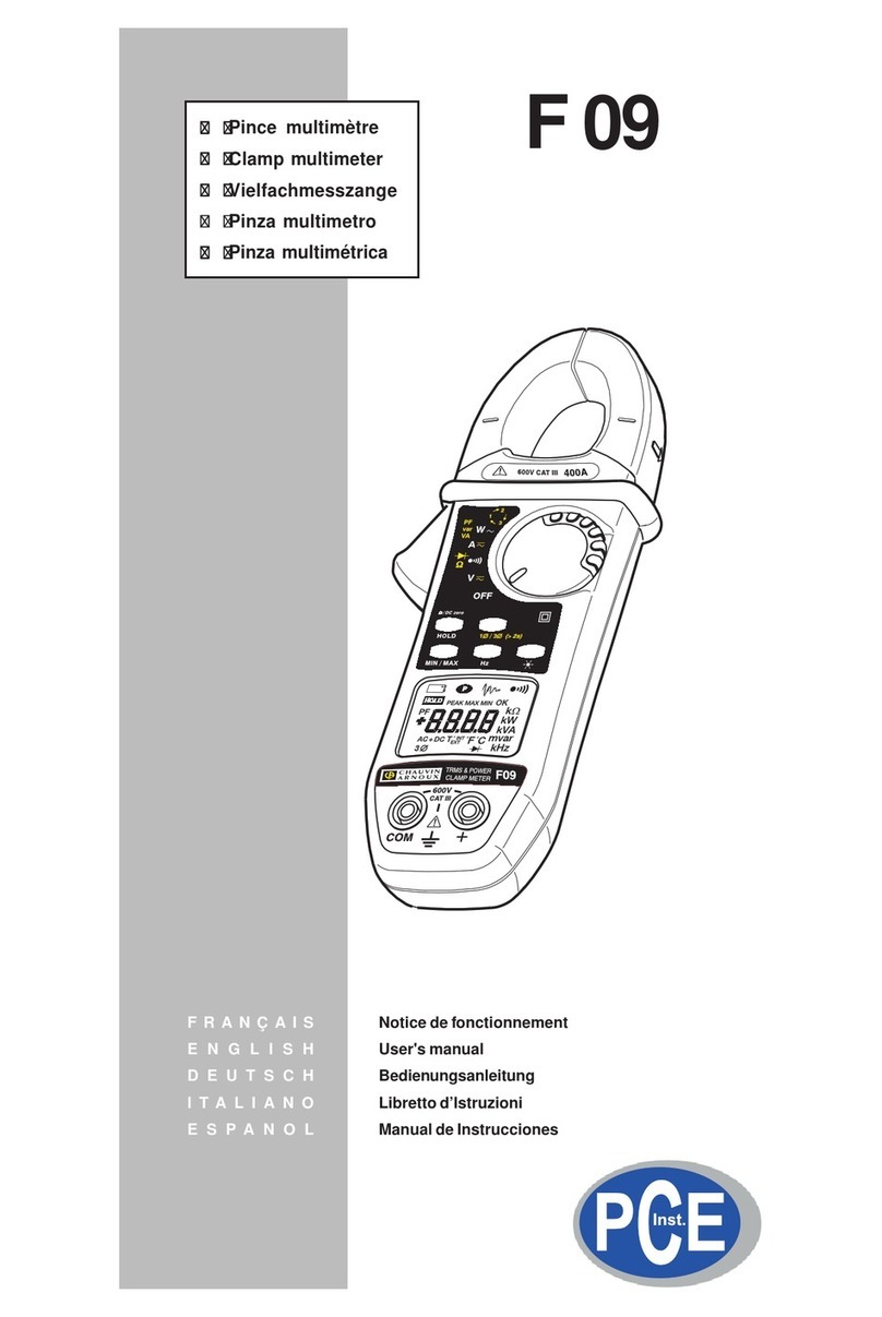
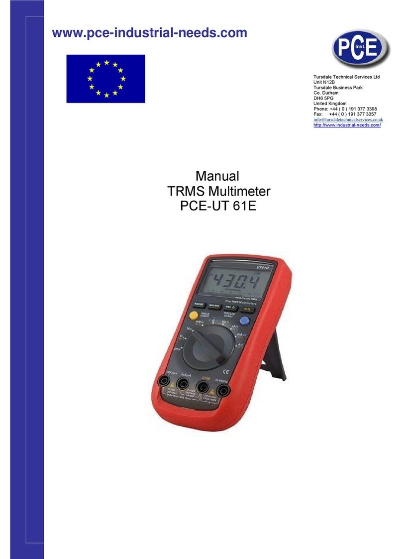
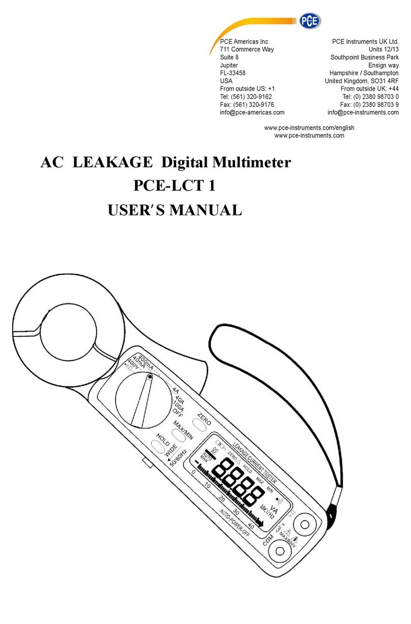
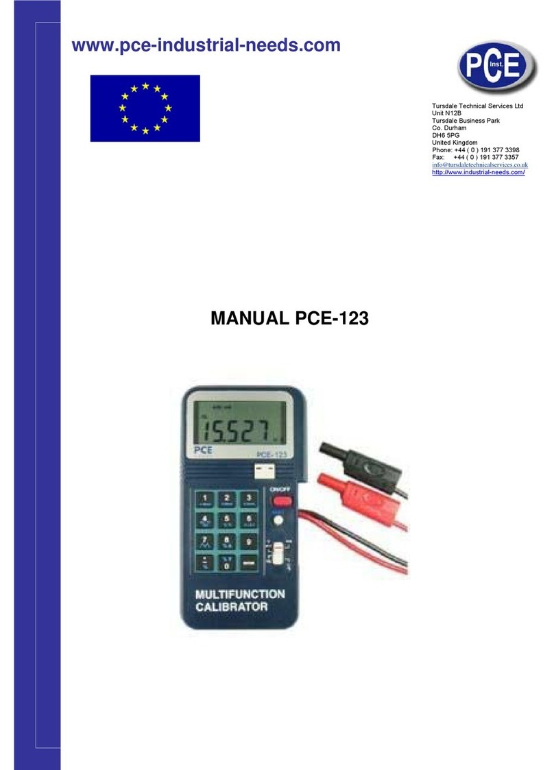
PCE Instruments PCE-DC2 User manual

PCE Americas Inc.
711 Commerce Way
Suite 8
Jupiter
FL-33458
USA
From outside US: +1
Tel: (561) 320-9162
Fax: (561) 320-9176
info@pce-americas.com
PCE Instruments UK Ltd.
Units 12/13
Southpoint Business Park
Ensign way
Hampshire / Southampton
United Kingdom, SO31 4RF
From outside UK: +44
Tel: (0) 2380 98703 0
Fax: (0) 2380 98703 9
info@pce-instruments.com
www.pce-instruments.com/english
www.pce-instruments.com
Manual
Multimeter PCE-DC2
Version 1.1
Date of creation: 16.02.2015
Date of last change: 21.10.2015

Manual
2
Contents
1Introduction .............................................................................................................3
2Safety notes.............................................................................................................3
3Specification............................................................................................................4
3.1 Technical specifications......................................................................................................... 4
3.2 Contents of delivery............................................................................................................... 4
4System description.................................................................................................5
4.1 Battery replacement............................................................................................................... 5
5Measuring ................................................................................................................5
5.1 AC current measurement....................................................................................................... 5
5.2 DC current measurement....................................................................................................... 6
5.3 AC/DC voltage measurement................................................................................................. 6
5.4 Non-contact voltage test........................................................................................................ 6
5.5 Resistance measuring and continuity test .............................................................................. 6
6Additional functions................................................................................................6
6.1 Flashlight............................................................................................................................... 6
6.2 Background lighting............................................................................................................... 7
6.3 Display hold........................................................................................................................... 7
6.4 Peak...................................................................................................................................... 7
6.5 Max/Min function ................................................................................................................... 7
6.6 Zeroing of DC currents........................................................................................................... 7
6.7 Auto power-off....................................................................................................................... 7
7Contact.....................................................................................................................8
7.1 PCE Instruments UK.............................................................................................................. 8
7.2 PCE Americas....................................................................................................................... 8

Manual
3
1 Introduction
Thank you for purchasing a current clamp from PCE Instruments.
With the current clamp PCE-DC2 you can measure AC/DC voltages and currents, as well as the electrical
resistance. The clamp mechanism of the PCE-DC2 enables you to perform non-contact current
measurements, while voltage and resistance measurements can be done by using the included test
leads. Due to its compact design, the current clamp is well-suited for mobile application. With its built-in
flashlight and the display with backlight, the current clamp can even be operated in areas with poor
lighting conditions.
2 Safety notes
Please read this manual carefully and completely before you use the device for the first time. The device
may only be used by qualified personnel and repaired by PCE Instruments personnel. There is no
warranty of damages or injuries caused by non-observance of the manual.
The device may only be used in approved temperature humidity range.
The device should not lay face down on the workbench or work surface to avoid damage to the
controls.
Avoid strong shocks.
Always keep the device clean and dry.
The appliance should only be cleaned with a damp cloth / use only pH-neutral cleaner.
Do not make any technical changes to the current probe.
The opening of the device and maintenance or repair work should only be done by qualified service
personnel of the PCE Instruments.
Before starting the measurement mode, the device should be stabilized to the ambient temperature.
Before each measurement, the device should be checked for damage.
Do not use the measuring clamp in the presence of flammable gases, vapours or solvents.
The device is intended for the use of interior spaces.
This user's handbook is published from PCE Instruments without any guarantee.
We expressly point to our general guarantee terms, they can be found in our general terms of business.
If you have any questions please contact PCE Instruments.

Manual
4
3 Specification
3.1 Technical specifications
AC current
(50 / 60 Hz) True RMS
Range: 200 A AC
Accuracy: ± (2.5 % + 8 dgt)
DC current
Range: 200 A DC
Accuracy: ± (2,0 % + 5dgt)
AC voltage
(50 / 60 Hz) True RMS
Range: 600 V AC
Accuracy: ± (1.5 % + 8 dgt)
DC voltage
Range: 600 V DC
Accuracy: ± (1.0 % + 8 dgt)
Resistance
Range: 999.9 Ω
Accuracy: ±(1,5 % + 8dgt)
Measuring point illumination
white LEDs
Conductor diameter
max. 18 mm
Display
3 2/3 Digit LCD with backlight
Power Supply
2 x 1.5 V AAA batteries
Housing
PVC
Temperature range
Operation: -10 … +50 °C
Storage: -30 … +60 °C
Air humidity range
90 % RH (0…30 °C)
75 % RH (30…40 °C)
45 % RH (40…50 °C)
Standardization
EN61010-1; CAT II 600V
EN61010-2-032; CAT III 300V
Dimensions
164 x 65 x 32 mm
Weight
175 g
3.2 Contents of delivery
1 x current clamp PCE-DC2
2 x test leads
1 x carrying bag
2 x batteries
1 x instruction manual

Manual
5
4 System description
1. Clamp mechanism
2. Light button
3. Rotary control switch
4. Peak/Max/Min button and zeroing of DC currents
5. LCD-Display
6. Clamp opening button
7. Hold button and display backlight
8. Non-contact voltage testing signal lamp
9. Non-contact voltage testing sensor surface
4.1 Battery replacement
To replace the batteries, lay the device face down on a soft surface. Next, open the cover of the battery
compartment on the back of the device. Remove the old batteries and replace them with new ones. After
that, close the battery compartment.
Note: Only use 1.5 V AAA batteries.
5 Measuring
Note: To avoid electric shocks, be very careful when measuring
current-carrying conductors.
Note: When using the clamp of the device, make sure there
is only one conductor at a time inside the clamp mechanism.
5.1 AC current measurement
1. Move the rotary control switch (3) to the “200 A AC”position.
2. Open the current clamp by using the opening button (6) and put the conductor to be measured
inside the clamp mechanism.
Note: Make sure there is only one conductor at a time inside the clamp mechanism.
3. You can now see the reading on the display

Manual
6
5.2 DC current measurement
1. Move the rotary control switch (3) to the “200 A DC”position.
2. Press and hold the zeroing button (4) for 2 seconds to perform a zeroing of the display.
3. Open the current clamp by using the opening button (6) and put the conductor to be measured
inside the clamp mechanism.
Note: Make sure there is only one conductor at a time inside the clamp mechanism.
4. You can now see the reading on the display
5.3 AC/DC voltage measurement
1. Connect the black test lead to the negative COM connector and the red test lead to the positive V
connector.
2. Move the rotary control switch (3) to the “V AC/DC” position.
3. Connect the test leads parallel to the component to be measured.
4. You can now see the reading on the display.
5.4 Non-contact voltage test
1. Move the top of the clamp close to the live conductor. For measuring purposes, it does not matter
if the conductor is insulated or not.
If you want to detect lead fractures move the current clamp along the conductor.
2. As long as the conductor is live, the signal lamp (8) is glowing.
Note: Electrostatic charging can also make the signal lamp glow.
5.5 Resistance measuring and continuity test
1. Connect the black test lead to the negative COM connector and the red test lead to the positive V
connector.
2. Move the rotary control switch (3) to the “Ω” position.
3. Connect the test leads to the component to be measured.
Note: It is best to disconnect the circuit to be measured before performing a test to prevent
interference with the reading.
4. Now you can see the reading on the display. If the resistance is below 30 Ω, the device plays an
acoustic alarm signal.
6 Additional functions
6.1 Flashlight
The current clamp comes with a built-in flashlight for working in areas with poor lighting conditions.
To turn the flashlight on, press the light button (2).

Manual
7
6.2 Display backlight
The display of the current clamp comes with a backlight. To activate it, press and hold the backlight
button (4) for 2 seconds. To turn the backlight back off, press and hold the button again for 2 seconds.
6.3 Display hold
You can freeze the current reading on the display at any time. To do so, simply press the Hold button (7).
By pressing the button again, you can unfreeze the reading.
6.4 Peak
If you are using the “200 A AC” measuring mode, you can press the Peak button (4) watch the peak
values. With this function, the device can capture peaks as fast as < 10 milliseconds in duration.
6.5 Max/Min function
You can use this function when using the “200 A DC”, the “V AC/DC” or the “Ω” mode.
Press the Peak/Max/Min (4) button to activate the Max/Min function. The display now shows the
maximum value and you can also see a “MAX” indication.
If you press the button again, the display shows the minimum value as well as a “MIN” indication.
Press the button once again to get to the MAX/MIN mode. In this mode the device shows the current
reading but stores and updates the minimum and maximum values at the same time.
To exit the Max/Min function, press and hold the Peak/Max/Min button for 2 seconds.
6.6 Zeroing of DC currents
By using this function, you can remove the offset values and improve the accuracy of the DC current
readings.
To do so, press and hold the zeroing button (4) for 2 seconds. A “Zero” indication appears on the display.
This means the offset value has been stored and removed from the readings.
To view the stored value, press the zeroing button. The “Zero” indication starts to flash and you can see
the value on the display.
To exit this mode, press and hold the zeroing button, until the “Zero” indication on the display disappears.
6.7 Auto power-off
The current clamp automatically shuts down after 7 minutes of idle time.

Manual
8
7 Contact
If you have any questions about our range of products or measuring instruments please contact PCE
Instruments.
7.1 PCE Instruments UK
By post:
PCE Instruments UK Ltd.
Units 12/13 Southpoint Business Park
Ensign Way, Southampton
Hampshire
United Kingdom, SO31 4RF
By phone:
02380 987 035
7.2 PCE Americas
By post:
PCE Americas Inc.
711 Commerce Way
Suite 8
Jupiter
33458 FL
USA
By phone:
561 320 9162
Table of contents
Other PCE Instruments Multimeter manuals

PCE Instruments
PCE Instruments PCE-IT 100 User manual

PCE Instruments
PCE Instruments PCE-UT 61E User manual

PCE Instruments
PCE Instruments PCE-TT 4 User manual

PCE Instruments
PCE Instruments PCE-AMM 5 User manual

PCE Instruments
PCE Instruments F09 User manual

PCE Instruments
PCE Instruments PCE-HVAC 6 User manual

PCE Instruments
PCE Instruments LCT 1 User manual

PCE Instruments
PCE Instruments PCE-123 User manual

PCE Instruments
PCE Instruments PCE-DM 22 User manual

PCE Instruments
PCE Instruments PCE-TT 3 User manual