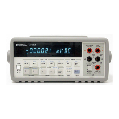
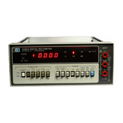
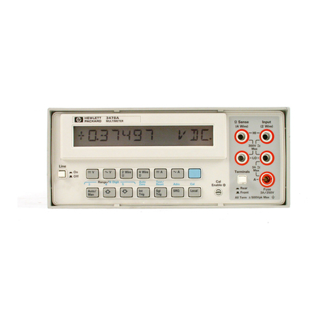
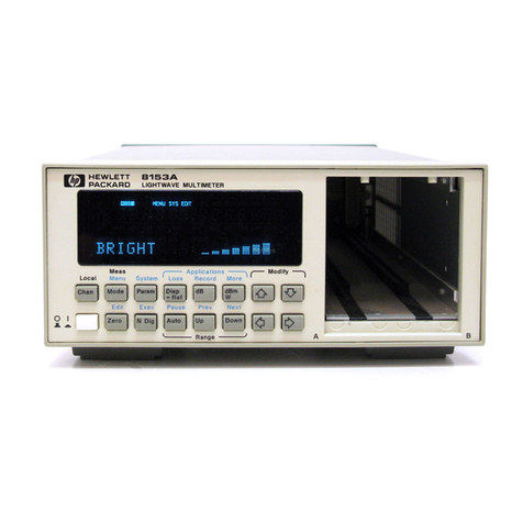
HP 3478A User manual

TM 11-6625-3071-14TM 11-6625-3071-14
TECHNICAL MANUALTECHNICAL MANUAL
OPERATOR’S ORGANIZATIONAL, DIRECT SUPPORT,OPERATOR’S ORGANIZATIONAL, DIRECT SUPPORT,
AND GENERAL SUPPORT MAINTENANCE MANUALAND GENERAL SUPPORT MAINTENANCE MANUAL
DILGITAL MULTIMETERDILGITAL MULTIMETER
HEWLETT - PACKARD MODEL 3478AHEWLETT - PACKARD MODEL 3478A
HEADQUARTERS, DEPARTMENT OF THE ARMYHEADQUARTERS, DEPARTMENT OF THE ARMY
5 MARCH 19855 MARCH 1985

TM 11-6625-3071-14TM 11-6625-3071-14
AA

TM 11-6625-3071-14TM 11-6625-3071-14
hp-HEWLETThp-HEWLETT
PACKARDPACKARD
SAFETY SUMMARYSAFETY SUMMARY
The following general safety precautions must be observed during all phases of operation, service, and repair ofThe following general safety precautions must be observed during all phases of operation, service, and repair of
this instrument Failure to comply with those precautions or with specific warnings elsewhere in this manualthis instrument Failure to comply with those precautions or with specific warnings elsewhere in this manual
violates safety standards of design, manufacture, and intended use of the instrument Hewlett Packard Companyviolates safety standards of design, manufacture, and intended use of the instrument Hewlett Packard Company
assumes no liability for the customer’s failure to comply with these requirements. This is a Safety Class 1assumes no liability for the customer’s failure to comply with these requirements. This is a Safety Class 1
instrumentinstrument
GROUND THE INSTRUMENTGROUND THE INSTRUMENT
To minimize shock hazard, the instrument chassis and cabinet must be connected to an electrical ground. The instrumentTo minimize shock hazard, the instrument chassis and cabinet must be connected to an electrical ground. The instrument
is equipped with a three-conductor ac power cable. The power cable must either be plugged into an approved three-is equipped with a three-conductor ac power cable. The power cable must either be plugged into an approved three-
contact electrical outlet or used with a three-contact to two-contact adapter with the grounding wire (green) firmlycontact electrical outlet or used with a three-contact to two-contact adapter with the grounding wire (green) firmly
connected to an electrical ground (safety ground) at the power outlet. The power jack and mating plug of theconnected to an electrical ground (safety ground) at the power outlet. The power jack and mating plug of the
power cable meet International Electrotechnical Commission (IEC) safety standards.power cable meet International Electrotechnical Commission (IEC) safety standards.
DO NOT OPERATE IN AN EXPLOSIVE ATMOSPHEREDO NOT OPERATE IN AN EXPLOSIVE ATMOSPHERE
Do not operate the instrument in the presence of flammable gases Do not operate the instrument in the presence of flammable gases
or fumes. Operation of or fumes. Operation of
any electrical instrument in suchany electrical instrument in such
an environment constitutes a definite safety hazard.an environment constitutes a definite safety hazard.
KEEP AWAY FROM LIVE CIRCUITSKEEP AWAY FROM LIVE CIRCUITS
Operating personnel must not remove instrument covers. Component replacement and internal adjustments must beOperating personnel must not remove instrument covers. Component replacement and internal adjustments must be
made by qualified maintenance personnel. Do not replace components with power cable connected. Under certainmade by qualified maintenance personnel. Do not replace components with power cable connected. Under certain
conditions, dangerous voltages may exist even with the power cable removed. To avoid injuries, always disconnect powerconditions, dangerous voltages may exist even with the power cable removed. To avoid injuries, always disconnect power
and discharge circuits before touching them.and discharge circuits before touching them.
DO NOT SERVICE OR ADJUST ALONEDO NOT SERVICE OR ADJUST ALONE
Do not attempt internal service or adjustment unless another person, capable of rendering first aid and resuscitation, isDo not attempt internal service or adjustment unless another person, capable of rendering first aid and resuscitation, is
present.present.
DO NOT SUBSTITUTE PARTS OR MODIFY INSTRUMENTDO NOT SUBSTITUTE PARTS OR MODIFY INSTRUMENT
Because of the danger of introducing additional hazards, do not install substitute parts or perform any unauthorizedBecause of the danger of introducing additional hazards, do not install substitute parts or perform any unauthorized
modification to the instrument. Return the instrument to a modification to the instrument. Return the instrument to a
Hewlett- Packard Sales and Service Office Hewlett- Packard Sales and Service Office
for service and repairfor service and repair
to ensure that safety features are maintained.to ensure that safety features are maintained.
DANGEROUS PROCEDURE WARNINGSDANGEROUS PROCEDURE WARNINGS
Warnings, such as the example below, precede potentially dangerous procedures throughout this manual. InstructionsWarnings, such as the example below, precede potentially dangerous procedures throughout this manual. Instructions
contained in the warnings must be followed.contained in the warnings must be followed.
Dangerous voltages, capable of causing death, are present in this Dangerous voltages, capable of causing death, are present in this
instrument Us ex-instrument Us ex-
treme caution when handling, testing, and adjusting.treme caution when handling, testing, and adjusting.
BB

TM 11-6625-3071-14TM 11-6625-3071-14
C/ (D BLANK)C/ (D BLANK)

TM 11-6625-3071-14TM 11-6625-3071-14
This manual contains copyright material reproduced by permission of the Hewlett-N Packard Company, Valley Forge, PAThis manual contains copyright material reproduced by permission of the Hewlett-N Packard Company, Valley Forge, PA
19482.19482.
TT
ee
cc
hh
nn
ii
cc
aa
l l
MM
aa
nn
uu
aa
ll
))
HH
EE
AA
DD
QQ
UU
AA
RR
TT
EE
RR
SS
))
DEPARTMENT OF THE ARMYDEPARTMENT OF THE ARMY
NN
oo
. .
11
11
--
66
66
22
55
--
33
00
77
11
--
11
4 4
))
WW
aa
ss
hh
ii
nn
gg
tt
oo
nn
, ,
DD
CC
, ,
5 5
MM
aa
rr
cc
h h
11
99
88
55
OPERATOR’S, ORGANIZATIONALOPERATOR’S, ORGANIZATIONAL
DIRECT SUPPORT, AND GENERAL SUPPORTDIRECT SUPPORT, AND GENERAL SUPPORT
MAINTENANCE MANUALMAINTENANCE MANUAL
DIGITAL MULTIMETER HP MODEL 3478ADIGITAL MULTIMETER HP MODEL 3478A
Serial Numbers: 2136A00101 and GreaterSerial Numbers: 2136A00101 and Greater
IMPORTANT NOTICEIMPORTANT NOTICE
If the Serial Number of your instrument is lower than the oneIf the Serial Number of your instrument is lower than the one
on this title page, the manual contains revisions that do noton this title page, the manual contains revisions that do not
apply to your instrument. Backdating information given inapply to your instrument. Backdating information given in
the manual adapts it to earlier instruments.the manual adapts it to earlier instruments.
Where practical, backdating information is integratedWhere practical, backdating information is integrated
intointo
the text, parts list and schematic diagrams. Backdatingthe text, parts list and schematic diagrams. Backdating
changes are denoted by a delta sign. An open delta (a) orchanges are denoted by a delta sign. An open delta (a) or
lettered delta (AA) on a given page, refers to thelettered delta (AA) on a given page, refers to the
corresponding backdating note on that page.corresponding backdating note on that page.
REPORTING ERRORS AND RECOMMENDING IMPROVEMENTSREPORTING ERRORS AND RECOMMENDING IMPROVEMENTS
You can help improve this manual. If you find any mistakes or ifYou can help improve this manual. If you find any mistakes or if
you know of a way to improve the procedures, please let usyou know of a way to improve the procedures, please let us
know. mail your letter, DA Form 2028 (recommended Changesknow. mail your letter, DA Form 2028 (recommended Changes
to Publications and Blank Forms), or DA Form 2028-2 located into Publications and Blank Forms), or DA Form 2028-2 located in
the back of this manual direct to: Commander, US Armythe back of this manual direct to: Commander, US Army
Communications-Electronics Command and Fort Monmouth,Communications-Electronics Command and Fort Monmouth,
ATTN: DRSEL-ME-MP, Fort Monmouth, NJ ATTN: DRSEL-ME-MP, Fort Monmouth, NJ
07703-5007.07703-5007.
In either case, a reply will be furnished direct to you.In either case, a reply will be furnished direct to you.
ii

TM 11-6625-3071-14TM 11-6625-3071-14
TABLE OF CONTENTSTABLE OF CONTENTS
Section PageSection Page
0.0.
INTRODUCTION INTRODUCTION
0-1.0-1.
Scope Scope
................................
....................................
....................................
....................................
....................................
....................................
............................
................................
.....0-1.....0-1
0-2.0-2.
Consolidated Consolidated
Index Index
of of
Army Army
Publications Publications
and and
Blank Blank
FormsForms
....................
....................
....................
....................
....................
..........
....0-1....0-1
0-3.0-3.
Maintenance Maintenance
Forms, Forms,
Records, Records,
and and
ReportsReports
..................
..................
..................
..................
..................
..................
..................
..................
..............
....0-1....0-1
0-4.0-4.
Reporting Reporting
Equipment Equipment
Improvement Improvement
Recommendations Recommendations
(EIR)(EIR)
....................
....................
....................
......................
....................
....0-1....0-1
0-5.0-5.
AdministrAdministr
ative ative
StorageStorage
....................................
....................................
....................................
....................................
....................................
........................
..................
....0-1....0-1
0-6.0-6.
Destruction Destruction
of of
Army Army
Electronics Electronics
MaterielMateriel
..................
..................
..................
..................
..................
..................
..................
..................
..................
......
....0-1....0-1
iiii

TM 11-6625-3071-14TM 11-6625-3071-14
TABLE OF CONTENTSTABLE OF CONTENTS
Section PageSection Page
I.I.
GENERAL GENERAL
INFORMATIONINFORMATION
..................
..................
............
...1-1...1-1
1-1.1-1.
Introduction................................... Introduction...................................
....1-1....1-1
1-3.1-3.
Section Section
I, I,
General General
Information.......Information.......
...1-1...1-1
1-5.1-5.
Section Section
II, II,
Installation Installation
ProceduresProcedures
..
...1-1...1-1
1-7.1-7.
Section Section
III, III,
Operation..................Operation..................
......
...1-1...1-1
1-9.1-9.
Section Section
IV, IV,
Performance Performance
Test Test
andand
CalibrationCalibration
1-11-1
1-11.1-11.
Section Section
V, V,
Replaceable Replaceable
Parts........Parts........
...1-1...1-1
1-13.1-13.
Section Section
VI, VI,
BackdatingBackdating
..................
..................
...1-1...1-1
1-15.1-15.
Section Section
VII, VII,
ServiceService
....................
....................
......
...1-1...1-1
1-17.1-17.
Appendix Appendix
AA
................
..................
..................
..................
..
...1-1...1-1
1-19.1-19.
Description..................................... Description.....................................
...1-1...1-1
1-22.1-22.
Specifications Specifications
................
..................
..................
..........
....1-1....1-1
1-24.1-24.
Instrument Instrument
and and
ManualManual
Identification...................................Identification...................................
...1-1...1-1
1-27.1-27.
OptionsOptions
..................
..................
..................
..................
..........
....1-2....1-2
1-29.1-29.
Accessories Accessories
Available.............Available.............
............
....1-2....1-2
Section PageSection Page
II.II.
INSTALLATIONINSTALLATION
..................
..................
..................
..................
..........
....2-1....2-1
2-1.2-1.
Introduction................................... Introduction...................................
....2-1....2-1
2-3.2-3.
Initial Initial
Inspection..............Inspection..............
..................
..........
....2-1....2-1
2-5.2-5.
Power Power
RequirementsRequirements
..................
......................
....2-1....2-1
2-7.2-7.
Line Line
Frequency Frequency
and and
LineLine
Voltage Voltage
Selection...........Selection...........
..................
..............
...2-1...2-1
2-9.2-9.
Power Power
Cords Cords
and and
ReceptaclesReceptacles
..........
....2-2....2-2
2-11.2-11.
Grounding Grounding
RequirementsRequirements
....................
......
....2-1....2-1
2-13.2-13.
Bench Bench
Use Use
and and
Rack Rack
MountingMounting
........
....2-2....2-2
2-14.2-14.
Bench Bench
UseUse
................
..................
..................
..................
..
....2-2....2-2
2-16.2-16.
Rack Rack
Mounting.........Mounting.........
..................
..................
......
....2-3....2-3
2-18.2-18.
HP-IB HP-IB
Interface Interface
ConnectionsConnections
................
....2-3....2-3
2-21.2-21.
Address Address
Selection..........Selection..........
..................
............
....2-3....2-3
2-24.2-24.
Environmental Environmental
RequirementsRequirements
..............
....2-3....2-3
2-25.2-25.
Operating Operating
and and
StorageStorage
TemperatureTemperature
................
..................
..................
..............
....2-3....2-3
2-27.2-27.
Repackaging Repackaging
for for
ShipmentShipment
....................
..
....2-4....2-4
Section PageSection Page
III.III.
OPERATIONOPERATION
..................
..................
..................
..................
..................
....3-1....3-1
3-1.3-1.
Introduction................................... Introduction...................................
....3-1....3-1
3-4.3-4.
General General
Information...........Information...........
..................
....
....3-1....3-1
3-5.3-5.
AC AC
Power Power
Operation.........Operation.........
..................
......
....3-1....3-1
3-7.3-7.
Turn-OnTurn-On
..................
..................
..................
..................
........
....3-1....3-1
3-10.3-10.
Display.......................................... Display..........................................
....3-1....3-1
3-12.3-12.
Input Input
Terminals...............Terminals...............
..................
..........
....3-3....3-3
3-15.3-15.
Input Input
Terminals Terminals
Cleaning.............Cleaning.............
..
....3-3....3-3
3-17.3-17.
Front Front
Panel Panel
OperationOperation
......................
..............
....3-3....3-3
3-18.3-18.
DC DC
Volts Volts
Measurements.....Measurements.....
....................
....3-3....3-3
3-22.3-22.
AC AC
Volts Volts
Measurements............Measurements............
......
....3-4....3-4
3-26.3-26.
Resistance Resistance
MeasurementsMeasurements
....................
..
....3-4....3-4
3-30.3-30.
DC DC
Current Current
Measurements......Measurements......
..........
....3-5....3-5
3-34.3-34.
AC AC
Current Current
Measurements...........Measurements...........
....3-5....3-5
3-38.3-38.
RangingRanging
..................
..................
..................
..................
......
........
..
3-53-5
3-43.3-43.
TriggeringTriggering
..................
..................
..................
..................
..
....3-5....3-5
3-50.3-50.
Shifted Shifted
Operation.........Operation.........
..................
................
....3-6....3-6
3-51.3-51.
General........................................ General........................................
........
..
3-63-6
3-54.3-54.
Number Number
of of
Digits Digits
Displayed...........Displayed...........
....
..
3-3-
66
3-57.3-57.
AutozeroAutozero
................
..................
..................
..................
........
....
....
3-73-7
3-60.3-60.
Self-Test/Reset Self-Test/Reset
Operation............Operation............
....
....
3-73-7
3-63.3-63.
CalibrationCalibration
................
..................
..................
..................
..
....
....
3-73-7
3-66.3-66.
Miscellaneous Miscellaneous
Operations............Operations............
....
....
3-83-8
3-67.3-67.
Voltmeter Voltmeter
Complete Complete
....................
....................
......
..
3-83-8
3-69.3-69.
Remote Remote
Operation.................Operation.................
..............
......
..
3-83-8
3-70.3-70.
General......................................... General.........................................
....
....
3-83-8
3-74.3-74.
3478A 3478A
Response Response
to to
Bus Bus
MessageMessage
s.s.
33
--
88
3-92.3-92.
3478A 3478A
Addressing.................Addressing.................
..............
......
..
3-13-1
00
3-96.3-96.
Talk-Only Talk-Only
Mode Mode
(No (No
Controller)Controller)
........
....
..
3-13-1
00
3-98.3-98.
3478A 3478A
HP-IB HP-IB
Programming.........Programming.........
....
......
3-13-1
11
3-117.3-117.
Advanced Advanced
Programming.........Programming.........
..............
......
3-13-1
44
Section PageSection Page
IV.IV.
PERFORMANCE PERFORMANCE
TEST TEST
ANDAND
CALIBRATIONCALIBRATION
................
..................
..................
..................
................
....
..
4-4-
11
4-1.4-1.
Introduction.................................... Introduction....................................
....
..
4-4-
11
4-4.4-4.
Equipment Equipment
Required.....Required.....
..................
................
....
..
4-4-
11
4-6.4-6.
DC DC
Volts Volts
Test Test
and and
CalibrationCalibration
..............
....
..
4-4-
11
4-10.4-10.
AC AC
Volts Volts
Test Test
and and
Calibration ...Calibration ...
......
....
..
4-4-
22
4-12.4-12.
Ohms Ohms
Test Test
and and
CalibrationCalibration
..................
..
....
....
4-4-
22
4-15.4-15.
DC DC
Current Current
Test Test
and and
Calibration...Calibration...
....
..
4-4-
33
4-20.4-20.
AC AC
Current Current
Test Test
and and
CalibrationCalibration
......
....
..
4-4-
33
4-24.4-24.
Test Test
CardsCards
....................................
....................................
....
....
4-4-
33
4-26.4-26.
Calibration Calibration
CycleCycle
................
..................
..................
..
....
..
4-4-
33
4-28.4-28.
Test Test
Failure Failure
....................................
................................
....
..
4-4-
33
4-30.4-30.
Instrument Instrument
Set-UpSet-Up
..................
..................
............
......
..
4-34-3
4-32.4-32.
Instrument Instrument
SpecificationSpecification
..................
..............
....
..
4-4-
33
4-35.4-35.
Specification Specification
Breakdown Breakdown
......................
......
....
..
4-4-
44
4-39.4-39.
Temperature Temperature
CoefficientCoefficient
(Reference (Reference
Temperature)Temperature)
..................
........
....
..
4-4-
44
4-41.4-41.
Test Test
ConsiderationConsideration
................
..................
............
......
..
4-44-4
4-42.4-42.
General......................................... General.........................................
....
....
4-44-4
4-44.4-44.
Ambiguous Ambiguous
RegionRegion
....................
....................
......
......
..
4-44-4
4-47.4-47.
Performance Performance
Test............Test............
..................
........
......
..
4-54-5
4-49.4-49.
DC DC
Volts Volts
TestTest
..................
..................
..................
........
....
....
4-54-5
4-54.4-54.
DC DC
Current Current
TestTest
................
..................
..................
..
......
..
4-74-7
4-59.4-59.
AC AC
Volts Volts
TestTest
..................
..................
..................
........
....
....
4-84-8
4-64.4-64.
AC AC
Current Current
TestTest
................
..................
..................
....
....
..
4-4-
99
4-69.4-69.
Ohms Ohms
Test.4-Test.4-
1010
......................................................
......
..
4-14-1
00
4-76.4-76.
Combined Combined
Calibration Calibration
andand
Performance Performance
TestsTests
..................
..................
............
......
4-14-1
11
4-77.4-77.
General......................................... General.........................................
....
....
4-14-1
11
4-80.4-80.
Calibrating Calibrating
the the
3478A..............3478A..............
............
....
..
4-14-1
22
4-82.4-82.
Calibration Calibration
Messages............Messages............
..............
......
..
4-14-1
33
4-84.4-84.
Calibration Calibration
Procedures............Procedures............
..........
......
..
4-14-1
33
4-86.4-86.
DC DC
Volts Volts
Calibration Calibration
and and
TestTest
..............
......
4-14-1
33
4-90.4-90.
DC DC
Current Current
Calibration Calibration
and and
Test...Test...
......
4-14-1
55
4-94.4-94.
AC AC
Volts Volts
Calibration Calibration
and and
TestTest
..............
......
4-14-1
66
4-99.4-99.
AC AC
Current Current
Calibration Calibration
andand
Test Test
(Optional............(Optional............
..................
..................
......
.. ..
4-4-
1818
4-103.4-103.
Ohms Calibration Ohms Calibration
and Testand Test
..................
....
......
4-14-1
88
iiiiii

TM 11-6625-3071-14TM 11-6625-3071-14
TABLE OF CONTENTS (TABLE OF CONTENTS (
Cont’d)Cont’d)
Section PageSection Page
V.V.
REPLACEABLE REPLACEABLE
PARTS............PARTS............
..................
............
....5-1....5-1
5-15-1
..
IntrIntr
oductoduct
ion.......ion.......
........
........
........
........
........
........
........
........
........
........
..
....5-1....5-1
5-45-4
..
OrderOrder
ing Informaing Informa
tion...tion...
........
........
........
........
........
........
........
........
...5-1...5-1
5-6.5-6.
Non-Listed Non-Listed
PartsParts
................
..................
..................
..................
..........
....5-1....5-1
5-8.5-8.
Parts Changed...........................................Parts Changed...........................................
....5-1....5-1
5-10.5-10.
Propriety Propriety
PartsParts
................
..................
..................
..................
..................
...5-1...5-1
5-12.5-12.
3478a 3478a
Disassembly Procedure.................Disassembly Procedure.................
..
....5-2....5-2
Section PageSection Page
VI.VI.
BACKDATINGBACKDATING
..................
..................
..................
..................
..............
....6-1....6-1
6-1.6-1.
Introduction................................... Introduction...................................
....6-1....6-1
Section PageSection Page
VII.VII.
SERVICESERVICE
................
..................
..................
..................
..................
..............
....7-1....7-1
7-17-1
..
IntrIntr
oductoduct
ion.......ion.......
........
........
........
........
........
........
........
........
........
........
..
....7-1....7-1
7-3.7-3.
Safety Safety
ConsiderationConsideration
................
..................
..................
..............
....7-1....7-1
7-8.7-8.
Recommended Test EquipmentRecommended Test Equipment
7-10.7-10.
Miscellaneous Miscellaneous
Information...............Information...............
....................
..
...7-1...7-1
7-11.7-11.
Instrument DisassemblyInstrument Disassembly
(PC (PC
Board Board
Replacement)Replacement)
..................
..................
..................
................
....
...7-1...7-1
7-13.7-13.
Fuse Fuse
ReplacementReplacement
..................
..................
..................
..................
....7-1....7-1
Section PageSection Page
7-15.7-15.
Troubleshooting.........................................Troubleshooting.........................................
....7-2....7-2
7-16.7-16.
Introduction................................................Introduction................................................
....7-2....7-2
7-18.7-18.
3478A Self-Test.........................................3478A Self-Test.........................................
....7-2....7-2
7-27.7-27.
Service Service
Group Group
Selection........Selection........
................
................
........
....7-2....7-2
Service Service
GroupsGroups
................
..................
..................
..................
..................
........Page........Page
AA
DC Volts and DC CurrentDC Volts and DC Current
TroubleshootingTroubleshooting
..................
..................
..................
..............
......
..
7-A7-A
-1-1
BB
AC Volts and AC CurrentAC Volts and AC Current
TroubleshootingTroubleshooting
..................
..................
..................
..............
......
7-B7-B
-1-1
CC
Ohms Ohms
Troubleshooting...............Troubleshooting...............
..................
......
........
7-C-7-C-
11
DD
A/D Converter and LogicA/D Converter and Logic
TroubleshootingTroubleshooting
..................
..................
..................
................
......
7-D-7-D-
11
EE
Power Supplies and ReferencePower Supplies and Reference
TroubleshootingTroubleshooting
..................
..................
..................
..............
......
7-E7-E
-1-1
FF
Theory of Theory of
OperationOperation
..................
..................
..................
..........
....7-F-1....7-F-1
Schematics...........Schematics...........
..................
..................
............
........
7-G-7-G-
1/1/
7-G-27-G-2
APPENDIX A...APPENDIX A...
................................................................................................
....
..
A-A-
11
B.B.
ReferencesReferences
................
..................
..................
..................
..
....
..
B-B-
11
C.C.
Components Components
of of
End End
ItemItem
List.................................................List.................................................
....
..
C-C-
11
D.D.
Additional Additional
AuthorizationAuthorization
List(Not Application:)List(Not Application:)
E. E.
Maintenance Maintenance
AllocationAllocation
......................
..................
E-1E-1
F. F.
Expendable Expendable
Supplies Supplies
andand
Material List(N/A)Material List(N/A)
LISTLIST
OO
FF
TABLESTABLES
Tables PageTables Page
3-13-1
..
ShiftShift
ed Operaed Opera
tions.....tions.....
........
........
........
........
........
........
........
......
..
....3-6....3-6
3-2.3-2.
3478A 3478A
Error Error
Messages...............Messages...............
..................
............
....3-7....3-7
3-3.3-3.
3478A 3478A
Bus Bus
Capabilities.....Capabilities.....
..................
..................
..............
....3-8....3-8
3-43-4
..
StatuStatu
s Byte Definits Byte Definit
ionsions
........
........
........
........
........
........
........
........
...3-10...3-10
3-5.3-5.
3478A 3478A
Address Address
Codes...........Codes...........
..................
..................
......
...3-11...3-11
3-6.3-6.
3478A Program 3478A Program
CodesCodes
..................
..................
..................
......
....3-12....3-12
3-73-7
..
Binary Binary
StatStat
us us
Byte Byte
DefinDefin
ition.......ition.......
........
........
........
......
...3-14...3-14
4-14-1
..
AbbAbb
revrev
iatiat
ed ed
SpeSpe
cifcif
icaica
tiotio
ns Tablens Table
......
......
......
......
....
..
...4-1...4-1
4-2.4-2.
Recommended Test EquipmentRecommended Test Equipment
....................
............
....4-2....4-2
4-3.4-3.
DC Volts DC Volts
Test LimitsTest Limits
................
..................
..................
................
....4-5....4-5
4-44-4
..
DC CDC C
urrenurren
t Tet Te
st st
LimitLimit
ss
........
........
........
........
........
........
........
....
....4-7....4-7
4-54-5
..
AC AC
Volts Volts
Test Test
LimitLimit
ss
........
........
........
........
........
........
........
........
....
....4-8....4-8
4-64-6
..
AC AC
CurreCurre
nt nt
Test Test
LimitLimit
ss
........
........
........
........
........
........
........
......
...4-9...4-9
4-7.4-7.
Ohms Test LimitsOhms Test Limits
..................
..................
..................
..................
....
....4-10....4-10
Tables PageTables Page
4-84-8
..
DC DC
Volts Volts
CalibrCalibr
ation ation
and and
Test.....Test.....
........
........
........
......
....
..
4-14-1
33
4-94-9
..
DC CurDC Cur
renren
t Calibt Calib
ratrat
ion and Teion and Te
st....st....
......
....
......
....
....
......
4-14-1
55
4-10.4-10.
AC Volts Calibration and TestAC Volts Calibration and Test
....................
....................
....
..
4-14-1
77
4-11.4-11.
AC Current Calibration and TestAC Current Calibration and Test
..................
..............
......
4-14-1
88
4-12.4-12.
Ohms Calibration and TesOhms Calibration and Tes
tt
....................
....................
........
......
4-14-1
99
5-15-1
..
StanStan
dard dard
AbbreAbbre
viativiati
ons......ons......
........
........
........
........
........
........
....
..
5-5-
11
5-25-2
..
Code Code
List List
of of
ManuManu
factufactu
rersrers
........
........
........
........
........
........
....
..
5-5-
22
5-3.5-3.
Replaceable Parts ListReplaceable Parts List
..................
..................
..................
......
......
..
5-35-3
5-4.5-4.
3478A Mechanical and3478A Mechanical and
Miscellaneous Miscellaneous
PartsParts
..................
..................
..................
................
....
..
5-5-
99
7-17-1
..
3478A 3478A
ServServ
ice ice
GroupGroup
s s
........
........
........
........
........
........
........
..
......
..
7-27-2
7-F-1.7-F-1.
Ohms Current and Ranges Ohms Current and Ranges
..................
......................
......
......
7-F7-F
-7-7
7-F-2.7-F-2.
AC AC
AmplifiAmplifi
er .....................er .....................
....................................
............
....
..
7-F7-F
-9-9
A-1.A-1.
3478A 3478A
Device Device
Capability ....Capability ....
....................
....................
....
......
..
A-3A-3
A-2.A-2.
HP-IB HP-IB
WorksheetWorksheet
................
..................
..................
..................
......
......
..
A-4A-4
iviv

TM 11-6625-3071-14TM 11-6625-3071-14
LIST OFLIST OF
ILLUSTRATIONSILLUSTRATIONS
Figure PageFigure Page
2-1.2-1.
Line Line
Frequency Frequency
Switch Switch
....................
............
....
....
2-12-1
2-2.2-2.
Line Line
Select Select
Jumper Jumper
................
..................
..........
......
..
2-22-2
2-3.2-3.
Power Power
Cords Cords
....................................
............................
......
..
2-22-2
2-4.2-4.
Typical Typical
HP-IB HP-IB
SystemSystem
Interconnection .............................Interconnection .............................
....
..
2-32-3
2-5.2-5.
HP-IB HP-IB
ConnectoConnecto
r r
....................................
..............
......
..
2-42-4
2-6.2-6.
3478A 3478A
Address Address
Switch Switch
..................
................
......
..
2-42-4
3-1.3-1.
3478A 3478A
Front Front
and and
Rear Rear
PanelPanel
Features ......................................Features ......................................
....3-2....3-2
3-2.3-2.
Typical Typical
Input Input
MeasurementMeasurement
Connection ....................................Connection ....................................
....
..
3-33-3
3-3.3-3.
Typical Typical
Current Current
MeasurementMeasurement
Connection ....................................Connection ....................................
....
..
3-33-3
3-4.3-4.
Ohms Ohms
Connections Connections
................
..................
..........
......
..
3-43-4
3-5.3-5.
Autoranging Autoranging
Points Points
................
..................
..........
......
..
3-63-6
3-6.3-6.
Status Status
Byte Byte
................................
..................................
......
..
3-93-9
4-1.4-1.
Ambiguous Ambiguous
Regions Regions
..................
......................
......
..
4-44-4
4-2.4-2.
DC DC
Volts Volts
Accuracy Accuracy
TestTest
and Calibration ..............................and Calibration ..............................
....
..
4-64-6
4-3.4-3.
DC DC
Common Common
Mode Mode
Rejection Rejection
TesTes
t...4-7t...4-7
4-4.4-4.
DC DC
Current Current
Accuracy Accuracy
TestTest
and Calibration ..............................and Calibration ..............................
....
..
4-84-8
4-5.4-5.
AC AC
Current Current
Accuracy Accuracy
TestTest
and Calibration ..............................and Calibration ..............................
....
..
4-14-1
00
4-6.4-6.
4-Wire 4-Wire
Ohms Ohms
Short Short
....................................
........
........
4-114-11
4-7.4-7.
4-Wire 4-Wire
Ohms Ohms
Connection Connection
..................
......
........
4-114-11
5-1.5-1.
3478A 3478A
Front Front
Panel Panel
ViewView
5-9/5-105-9/5-10
5-2.5-2.
3478A 3478A
Rear Rear
Panel Panel
ViewView
5-9/5-105-9/5-10
5-3.5-3.
3478A 3478A
Bottom Bottom
ViewView
..
5-9/5-105-9/5-10
5-4.5-4.
3478A 3478A
Left Left
Side Side
ViewView
5-9/5-105-9/5-10
5-5.5-5.
Bottom Bottom
View View
WithWith
Cover Removed ............................Cover Removed ............................
....
..
5-15-1
11
5-6.5-6.
Top Top
View View
WithWith
Cover Removed.............................Cover Removed.............................
....
..
5-15-1
11
5-7.5-7.
Front Front
Panel Panel
Bracket Bracket
View View
..................
........
...5-11...5-11
5-8.5-8.
Front Front
Panel Panel
Assembly Assembly
......................
................
...5-11...5-11
7-A-17-A-1
..
JM4JM4
03 SA Con03 SA Con
necnec
tiotio
n n
......
......
......
......
....
......
........
7-A-7-A-
44
7-B-1.7-B-1.
JM403 JM403
SA SA
Connection Connection
....................
..............
........
7-B-27-B-2
7-C-17-C-1
..
JM40JM40
3 3
SA SA
ConneConne
ctionction
. .... ...
........
........
........
....
......
7-C-7-C-
44
7-D-1.7-D-1.
US01 US01
ALE ALE
Signal ........Signal ........
..................
..................
......
7-D-7-D-
22
7-D-27-D-2
..
FlowchFlowch
art Aart A
........
........
........
........
........
........
........
........
........
......
7-D-7-D-
33
Figure PageFigure Page
7-D-3.7-D-3.
Flowchart Flowchart
BB
..................
..................
..................
................
......
7-D7-D
-5-5
7-D-4.7-D-4.
FlowchaFlowcha
rt rt
C C
....................................
................................
......
7-D7-D
-6-6
7-D-5.7-D-5.
U462 U462
ALE ALE
Signal Signal
..................
..................
................
....
..
7-D7-D
-8-8
7-D-6.7-D-6.
FlowchaFlowcha
rt rt
D D
....................................
................................
......
7-D7-D
-9-9
7-D-7.7-D-7.
JM403 JM403
SA SA
Connection......Connection......
....................
....
...7-D-10...7-D-10
7-F-1.7-F-1.
3478A 3478A
Simplified Simplified
BlockBlock
Diagram .......................................Diagram .......................................
......
..
7-F7-F
-2-2
7-F-2.7-F-2.
Simplified Simplified
Schematic Schematic
of of
thethe
Input Switching Circuitry Input Switching Circuitry
....................
..........
......
7-F7-F
-4-4
7-F-3.7-F-3.
Simplified Simplified
Schematic Schematic
of of
thethe
DC/Ohms InpuDC/Ohms Inpu
t Amplifier t Amplifier
..................
........
......
7-F7-F
-6-6
7-F-4.7-F-4.
Ohms Ohms
Circuitry Circuitry
Configuration Configuration
................
....
7-7-
F-F-
66
7-F-5.7-F-5.
AC AC
Gain Gain
Configurations Configurations
..................
..............
......
7-F7-F
-8-8
7-F-6.7-F-6.
Dual Dual
Slope Slope
Conversion Conversion
......................
............
......
7-F7-F
-9-9
7-F-7.7-F-7.
Simplified Simplified
A/D A/D
Converter Converter
......................
..
....
7-F-7-F-
1010
7-F-8.7-F-8.
Integrator Integrator
(U401) (U401)
OutputOutput
Slopes ......................................Slopes ......................................
....7-F-10....7-F-10
7-F-9.7-F-9.
Runup Runup
SlopesSlopes
(4 1/2 Digit Model) (4 1/2 Digit Model)
....................
....................
....
....
7-F-17-F-1
11
7-F-10. Runup Slopes For Zero Inputs7-F-10. Runup Slopes For Zero Inputs
4 4
1/2 1/2
Model) Model)
................................
............................
......
7-F-7-F-
1212
7-F-11.7-F-11.
Slope Slope
S S
+ +
4 4
Generation Generation
..................
........
......
7-F-7-F-
1212
7-F-12.7-F-12.
Slope Slope
S S
- -
4 4
Generation Generation
......................
......
......
7-F-7-F-
1212
7-F-13.7-F-13.
Slope Slope
S+0 S+0
and and
S-0S-0
Generation ................................Generation ................................
....7-F-13....7-F-13
7-F-14.7-F-14.
Rundown Rundown
Slopes Slopes
....................
......................
..
....7-F-13....7-F-13
7-F-15.7-F-15.
Determining Determining
the the
DAC DAC
Setting Setting
........
......
7-F-17-F-1
55
7-F-16.7-F-16.
A/D A/D
Hybrid Hybrid
(U403) (U403)
....................
....................
....
....
7-F-17-F-1
55
7-F-17.7-F-17.
3478A 3478A
Simplified Simplified
ReferenceReference
Circuitry .....................................Circuitry .....................................
......
7-F-7-F-
1616
7-F-18.7-F-18.
Power-On Power-On
Circuitry Circuitry
....................
....................
......
7-F-17-F-1
77
7-F-19.7-F-19.
Reset Reset
CircuiCircui
try try
....................................
..................
......
7-F-7-F-
1818
7-G-1.7-G-1.
General General
Schematic Schematic
Notes Notes
....................
....
......
7-G7-G
-1-1
7-G-2.7-G-2.
3478A 3478A
Block Block
Diagram Diagram
....................
................
......
7-G7-G
-3-3
7-G-3.7-G-3.
Input Input
Circuitry Circuitry
andand
Ohms Current SourceOhms Current Source
7-G-5/7-G-67-G-5/7-G-6
7-G-4.7-G-4.
AC AC
to to
DC DC
Converter Converter
....................
....................
..
....
..
7-G7-G
-7-7
7-G-5.7-G-5.
A/D A/D
Converter Converter
andand
Control Logic Control Logic
....................
..................
......
7-G-97-G-9
/7-G/7-G
-10-10
7-G-6.7-G-6.
Power Power
Supplies Supplies
..................
......
......
7-G-11/7-G-127-G-11/7-G-12
A-1.A-1.
Interface Interface
Connection Connection
andand
Bus Structure............................Bus Structure............................
....
..
A-A-
22
vv

TM 11-6625-3071-14TM 11-6625-3071-14
SECTION 0SECTION 0
INTRODUCTIONINTRODUCTION
00
--
11
..
SS
CC
OO
PP
EE
This manual describes the This manual describes the
Digital Multimeter, HP Model 3478A and Digital Multimeter, HP Model 3478A and
provides instructions for operation and maintenance.provides instructions for operation and maintenance.
0-0-
2.2.
COCO
NSNS
OLOL
IDID
ATAT
ED IED I
NDND
EX OEX O
F ARF AR
MY PMY P
UBUB
LILI
CACA
TITI
ONON
S AND BS AND B
LALA
NK FNK F
OROR
MSMS
Refer to the latest issue of DA Refer to the latest issue of DA
Pam 310-1 to determine whether there are new editions, changes or Pam 310-1 to determine whether there are new editions, changes or
additional publicationsadditional publications
pertaining to the equipment.pertaining to the equipment.
0-0-
3.3.
MAMA
ININ
TETE
NANA
NCNC
E FOE FO
RMRM
S, RS, R
ECEC
OROR
DSDS
, AN, AN
D RED RE
POPO
RTRT
SS
a.a.
ReporRepor
ts of Maintets of Mainte
nance and Unnance and Un
satisfsatisf
actoractor
y Equipy Equip
ment. Depment. Dep
artmeartme
nt of the Army forms and procent of the Army forms and proce
dures used fordures used for
equipment maintenance will be those prescribed by DA Pam 738-750, as contained in Maintenance Managementequipment maintenance will be those prescribed by DA Pam 738-750, as contained in Maintenance Management
Update.Update.
b.b.
ReporRepor
t of Packagit of Packagi
ng and Hanng and Han
dling Dedling De
ficienficien
cies. Filcies. Fil
l out and forwl out and forw
ard SF 364 (Repoard SF 364 (Repo
rt of Discreprt of Discrep
ancy (Rancy (R
OD)) asOD)) as
prescribed in AR 735-11-2/DLAR 4140.55/ NAVMATINST 4355.73A/AFR 400-54/MCO 4430.3F.prescribed in AR 735-11-2/DLAR 4140.55/ NAVMATINST 4355.73A/AFR 400-54/MCO 4430.3F.
c.c.
DiscreDiscre
pancy ipancy i
n Shipment Ren Shipment Re
port (DIport (DI
SREP)SREP)
(SF 361)(SF 361)
. Fill out and forwa. Fill out and forwa
rd Discreprd Discrep
ancy in Shipmancy in Shipm
ent Reporent Repor
tt
(DISREP)(SF 361) as prescribed in AR 55-38/ NAVSUPINST 4610.33C/AFR 75-18/MCO P4610.19D/DLAR(DISREP)(SF 361) as prescribed in AR 55-38/ NAVSUPINST 4610.33C/AFR 75-18/MCO P4610.19D/DLAR
4500.15.4500.15.
0-0-
4.4.
RERE
POPO
RTRT
ININ
G EQUIG EQUI
PMPM
ENEN
T IMPT IMP
RORO
VEVE
MEME
NT RECNT REC
OMOM
MEME
NDND
ATAT
IOIO
NS (EINS (EI
R)R)
If your equipment needs improvement, let us know. Send us an EIR. You, the user, are the only one who can tell us whatIf your equipment needs improvement, let us know. Send us an EIR. You, the user, are the only one who can tell us what
you don’t like about your equipment. Let us know why you don’t like the design. Put it on an SF 368 (Quality Deficiencyyou don’t like about your equipment. Let us know why you don’t like the design. Put it on an SF 368 (Quality Deficiency
Report). Mail it to Commander, US Army Communications-Electronics Command and Fort Monmouth, ATTReport). Mail it to Commander, US Army Communications-Electronics Command and Fort Monmouth, ATT
N: DRSEL-ME-N: DRSEL-ME-
MP, Fort Monmouth, NJ 07703-5007. We’ll send you a reply.MP, Fort Monmouth, NJ 07703-5007. We’ll send you a reply.
00
--
55
..
AA
DD
MM
II
NN
II
SS
TT
RR
AA
TT
II
VV
E STE ST
OO
RR
AA
GG
EE
Administrative storage of equipment issued to and used by Army activities will have preventive maintenance performed inAdministrative storage of equipment issued to and used by Army activities will have preventive maintenance performed in
accordance with the PMCS charts for storing. When removing the equipment from administrative storage the PMCSaccordance with the PMCS charts for storing. When removing the equipment from administrative storage the PMCS
should be performed to assure operational readiness. Disassembly and repacking of equipment for shipment or limitedshould be performed to assure operational readiness. Disassembly and repacking of equipment for shipment or limited
storage is covered instorage is covered in
paragraph 2-27.paragraph 2-27.
0-0-
6.6.
DEDE
STST
RURU
CTCT
IOIO
N N
OF OF
ARAR
MY MY
ELEL
ECEC
TRTR
ONON
ICIC
S S
MAMA
TETE
RIRI
ELEL
Destruction of Army electronics materiel to prevent enemy use shall be in accordance with TM 750-244-2.Destruction of Army electronics materiel to prevent enemy use shall be in accordance with TM 750-244-2.
0-10-1

TM 11-6625-3071-14TM 11-6625-3071-14
SECTION ISECTION I
GENERAL INFORMATIONGENERAL INFORMATION
The information in this manual is for the use of ServiceThe information in this manual is for the use of Service
Trained Personnel. To avoid electrical shock, do notTrained Personnel. To avoid electrical shock, do not
perform any procedures in the manual or do anyperform any procedures in the manual or do any
servicing to the 3478A unless you are qualified to do servicing to the 3478A unless you are qualified to do
so.so.
11
--
11
..
II
NN
TT
RR
OO
DD
UU
CC
TT
II
OO
NN
1-1-
2.2.
ThTh
e ine in
fofo
rmarma
titi
on on
in in
thth
is mis m
anan
uaua
l is l is
fofo
r tr t
he Ihe I
nsns
tata
llll
tion, Operation, Performance, Calibration, and Service tion, Operation, Performance, Calibration, and Service
ofof
the 3478A Digital Multimeter. The manual is designed forthe 3478A Digital Multimeter. The manual is designed for
the use of Service Trained Personnel. Other use shouldthe use of Service Trained Personnel. Other use should
refer to the Operators Manual. This manual separatedrefer to the Operators Manual. This manual separated
into the following sections.into the following sections.
1-3. Section I, General Information1-3. Section I, General Information
1-1-
4.4.
A sA s
hoho
rt rt
dede
scsc
riri
ptpt
ioio
n on o
f tf t
he he
mama
nunu
al al
anan
dd
introduction to the 3478A is in Section 1. The sectionintroduction to the 3478A is in Section 1. The section
also lists instrument options, specifications, andalso lists instrument options, specifications, and
accessories.accessories.
1-1-
5.5.
SeSe
ctct
ioio
n In I
I, I,
InIn
stst
alal
lala
titi
on on
PrPr
ococ
eded
urur
eses
1-1-
6.6.
ThTh
is sis s
ecec
titi
on on
exex
plpl
aiai
ns ns
hoho
w tw t
he he
3434
7878
A iA i
s ps p
rere
papa
rere
for use and includes power requirements, line voltagefor use and includes power requirements, line voltage
selection, etc. The section also explains how to connectselection, etc. The section also explains how to connect
the multimeter for remote operation.the multimeter for remote operation.
11
--
77
..
SS
ee
cc
tt
ii
oo
n n
IIII
I, I,
OO
pp
ee
rr
aa
tt
ii
oo
nn
1-1-
8.8.
ThTh
e coe co
ndnd
enen
sese
d od o
pepe
rara
titi
ng ng
inin
stst
ruru
ctct
ioio
ns ons o
f 34f 34
7878
A,A,
for the use of Service Trained Personnel, is this section.for the use of Service Trained Personnel, is this section.
For more complete instructions, refer to OperatorsFor more complete instructions, refer to Operators
Manual.Manual.
1-1-
9.9.
SeSe
ctct
ioio
n In I
V, V,
PePe
rfrf
oror
mama
ncnc
e Te T
eses
t at a
nd nd
CaCa
lili
brbr
atat
ioio
nn
1-11-1
0.0.
The The
347347
8A’8A’
s Pes Pe
rforfo
rmarma
nce nce
TesTes
t ant an
d Cad Ca
liblib
ratrat
ionion
Procedures are in Section IV. The Required EquipmentProcedures are in Section IV. The Required Equipment
Table and an abbreviated specification table are alsoTable and an abbreviated specification table are also
included.included.
1-1-
1111
..
SeSe
ctct
ioio
n n
V, V,
ReRe
plpl
acac
eaea
ble ble
PaPa
rtrt
ss
1-11-1
2.2.
SecSec
tiotio
n V ln V l
istist
s ths th
e ree re
plapla
ceacea
ble ble
parpar
ts ots o
f thf th
e 34e 34
78t78t
It also includes pictures and illustrations of chassis andIt also includes pictures and illustrations of chassis and
mechanical parts.mechanical parts.
1-1-
1313
..
SeSe
ctct
ioio
n Vn V
I, I,
BaBa
ckck
dada
titi
ngng
1-11-1
4.4.
This This
secsec
tiotio
n han ha
s ins in
forfor
matmat
ion ion
whiwhi
ch ach a
dapdap
ts tts t
hishis
manual to 3478A’s with serial numbers below the onesmanual to 3478A’s with serial numbers below the ones
shown on the title page.shown on the title page.
1-1-
1515
..
SeSe
ctct
ioio
n n
VIVI
I, I,
SeSe
rvrv
icic
ee
1-11-1
6.6.
The The
347347
8A’8A’
s Ts T
rourou
bleble
shosho
otioti
ng ng
ProPro
cedced
ureure
s,s,
Theory Of Operation, and Schematics are in Section VII.Theory Of Operation, and Schematics are in Section VII.
The troubleshooting information is in the form of ServiceThe troubleshooting information is in the form of Service
Groups which are symptoms oriented (i.e., what is theGroups which are symptoms oriented (i.e., what is the
failure). The complete theory of operation is in Servicefailure). The complete theory of operation is in Service
Group F and the Schematics are in Service Group GGroup F and the Schematics are in Service Group G
(last group).(last group).
11
--
11
77
..
AA
pp
pp
ee
nn
dd
ii
x x
AA
1-11-1
8.8.
The The
appapp
endend
ix hix h
as a as a
concon
denden
sed sed
desdes
cricri
ptipti
on on
ofof
the HP-IB (Hewlett-Packard Interface Bus).the HP-IB (Hewlett-Packard Interface Bus).
11
--
11
99
..
DD
EE
SS
CC
RR
II
PP
TT
II
OO
NN
1-20. The -hp- Model 3478A is a versatile multimeter1-20. The -hp- Model 3478A is a versatile multimeter
with dc and ac volts, dc and ac currents, and resistancewith dc and ac volts, dc and ac currents, and resistance
measurement capabilities. The multimeter is excellent formeasurement capabilities. The multimeter is excellent for
bench use, and since it is remotely programmable, it canbench use, and since it is remotely programmable, it can
be used in measurement systems. A feature of thebe used in measurement systems. A feature of the
instrument is that the reading can be displayed in instrument is that the reading can be displayed in
either 5either 5
1/2, 4 1/2, or 3 1/2 digits. Other features are Autozero1/2, 4 1/2, or 3 1/2 digits. Other features are Autozero
(for good stability), and an Alphanumeric Liquid Crystal(for good stability), and an Alphanumeric Liquid Crystal
Display.Display.
1-21-2
1.1.
AnoAno
thethe
r er e
xcexce
llelle
nt nt
feafea
tutu
re re
is is
EleEle
ctrctr
onioni
cc
Calibration. No mechanical adjustments are necessary toCalibration. No mechanical adjustments are necessary to
calibrate the 3478A.calibrate the 3478A.
1-1-
2222
..
SPSP
ECEC
IFIF
ICIC
ATAT
IOIO
NSNS
1-21-2
3.3.
SpeSpe
cificifi
catcat
ionion
s of s of
the the
347347
8A a8A a
re tre t
he phe p
erferf
ormorm
ancanc
ee
characteristics of the multimeter which are certified. Thecharacteristics of the multimeter which are certified. The
specifications are listed inspecifications are listed in
Table 1-1 Table 1-1
andand
Table 4-1 Table 4-1
(in(in
Section IV). They are the performance standards orSection IV). They are the performance standards or
limits against which the limits against which the
multimeter can be tested.multimeter can be tested.
1-1-
2424
..
INSINS
TRTR
UMUM
ENEN
TATA
NDND
MAMA
NUNU
AL AL
IDID
ENEN
TITI
FIFI
CACA
TIOTIO
NN
1-21-2
5.5.
InsIns
trutru
menmen
t Idt Id
entent
ifiifi
catcat
ion iion i
s by s by
a sera ser
ial nial n
umbumb
erer
located on the multimeter’s rear panel. Hewlett-Packardlocated on the multimeter’s rear panel. Hewlett-Packard
uses a two-part serial number, with the first part (prefix)uses a two-part serial number, with the first part (prefix)
identifying a series of identifying a series of
instruments and theinstruments and the
1-11-1

TM 11-6625-3071-14TM 11-6625-3071-14
Table 1-1. SpecificationTable 1-1. Specification
1-21-2

TM 11-6625-3071-14TM 11-6625-3071-14
Table 1-1. Specifications. Cont.Table 1-1. Specifications. Cont.
1-31-3

TM 11-6625-3071-14TM 11-6625-3071-14
Table 1-1. Specifications. Cont.Table 1-1. Specifications. Cont.
1-41-4

TM 11-6625-3071-14TM 11-6625-3071-14
3478A3478A
second part (suffix) identifying a particular instrumentsecond part (suffix) identifying a particular instrument
within a series. An -hp- assigned alpha character lwithin a series. An -hp- assigned alpha character l
between the prefix and suffix identifies the country whichbetween the prefix and suffix identifies the country which
the 3478A was manufactured.the 3478A was manufactured.
1-21-2
6.6.
ThiThi
s mas ma
nuanua
l apl ap
plipli
es tes t
o ino in
strstr
umeume
nts nts
witwit
h thh th
ee
serial number identified on the title page. Updating of theserial number identified on the title page. Updating of the
manual is accomplished either by a change sheetmanual is accomplished either by a change sheet
revised manual.revised manual.
11
--
22
77
..
OO
PP
TT
II
OO
NN
SS
1-21-2
8.8.
The The
folfol
lowlow
ing ing
optopt
ionion
s as a
re are a
vaivai
lablab
le fle f
or or
thethe
3478A.3478A.
Option 315: set for 100V, 50Hz Power SourceOption 315: set for 100V, 50Hz Power Source
Option 316: set for 100V, 60Hz Power SourceOption 316: set for 100V, 60Hz Power Source
Option 325: set for 120V, 50OHz Power SourceOption 325: set for 120V, 50OHz Power Source
Option 326: set for 120V, 60Hz Power SourceOption 326: set for 120V, 60Hz Power Source
Option 335: set for 220V, 50Hz Power SourceOption 335: set for 220V, 50Hz Power Source
Option 336: set for 220V, 60Hz Power SourceOption 336: set for 220V, 60Hz Power Source
Option 345: set for 240V, 50OHz Power SourceOption 345: set for 240V, 50OHz Power Source
Option 346: set for 240V, 60Hz Power SourceOption 346: set for 240V, 60Hz Power Source
Option 907: Front Handle Kit (-hp- Part No.Option 907: Front Handle Kit (-hp- Part No.
5061-1088)5061-1088)
Option 908: Option 908:
Rack Mount Rack Mount
Kit includes Kit includes
one rack flanone rack flan
gege
and one extension adapter (-hp- Part and one extension adapter (-hp- Part
No. 5061-0072)No. 5061-0072)
Option Option
910: 910:
additional additional
set set
of Operatof Operat
ors and ors and
ServiceService
Manuals.Manuals.
1-29. 1-29.
ACCESSORIES ACCESSORIES
AVAILABLEAVAILABLE
1-30. 1-30.
The following The following
is a list is a list
of available of available
accessories foraccessories for
the 3478A.the 3478A.
Accessory No.Accessory No.
DescriDescri
ptionption
11
00
00
22
33
AA
TT
ee
mm
pp
ee
rr
aa
tt
uu
rr
e e
PP
rr
oo
bb
ee
11
00
66
33
11
AA
HH
PP
--
II
B B
CC
aa
bb
ll
e e
1 1
mm
ee
tt
ee
r r
((
33
99
..
33
7 7
ii
nn
))
11
00
66
33
11
BB
HH
PP
--
II
B B
CC
aa
bb
ll
e e
1 1
mm
ee
tt
ee
r r
((
77
88
..
77
4 4
ii
nn
))
11
00
66
33
11
CC
HH
PP
--
II
B B
CC
aa
bb
ll
e e
1 1
mm
ee
tt
ee
r r
((
11
55
77
..
44
8 8
ii
nn
))
11
00
66
33
11
DD
HH
PP
--
II
B B
CC
aa
bb
ll
e e
1 1
mm
ee
tt
ee
r r
((
11
99
..
66
9 9
ii
nn
))
11
11
00
00
00
AA
TT
ee
ss
t t
ll
ee
aa
dd
ss
, ,
dd
uu
aa
l l
bb
aa
nn
aa
nn
a a
bb
oo
tt
hh
endsends
11
11
00
00
22
AA
TT
ee
ss
t t
ll
ee
aa
dd
ss
, ,
dd
uu
aa
l l
bb
aa
nn
aa
nn
a a
tt
o o
dd
uu
aa
ll
alligatoralligator
11
11
00
00
33
AA
TT
ee
ss
t t
ll
ee
aa
dd
ss
, ,
dd
uu
aa
l l
bb
aa
nn
aa
nn
a a
tt
oo
probe and alligatorprobe and alligator
11
11
00
99
66
BB
RR
F F
PP
rr
oo
bb
ee
33
44
11
11
11
AA
HH
ii
gg
h h
VV
oo
ll
tt
aa
gg
e e
PP
rr
oo
bb
ee
33
44
11
11
88
AA
TT
ee
ss
t t
ll
ee
aa
dd
ss
, ,
dd
uu
aa
l l
bb
aa
nn
aa
nn
a a
tt
oo
probes with Safety Guard Ringsprobes with Safety Guard Rings
1-5/(1-6 blank)1-5/(1-6 blank)

TM 11-6625-3071-14TM 11-6625-3071-14
SECTION IISECTION II
INSTALLATIONINSTALLATION
2-1. INTRODUCTION2-1. INTRODUCTION
2-2. 2-2.
This This
section section
of of
the the
manual manual
has has
the the
necessarynecessary
information and instructions to install and interface the -hiinformation and instructions to install and interface the -hi
Model 3478A Digital Multimeter. Included are initialModel 3478A Digital Multimeter. Included are initial
inspection procedures, power requirements,inspection procedures, power requirements,
environmental information, and instructions for repackingenvironmental information, and instructions for repacking
the instrument for shipment. The information in thisthe instrument for shipment. The information in this
section is for Service Trained Personnel.section is for Service Trained Personnel.
The information in this manual is for the use ofThe information in this manual is for the use of
Service Trained Personnel. To avoid electrical shock, doService Trained Personnel. To avoid electrical shock, do
not perform any procedures in this manual or do anynot perform any procedures in this manual or do any
servicing to the 3478A unless you are qualified to do servicing to the 3478A unless you are qualified to do
so.so.
2-3. 2-3.
INITIAL INITIAL
INSPECTIONINSPECTION
2-4. 2-4.
The The
3478A 3478A
was was
carefully carefully
inspected inspected
botbot
mechanically and electrically before shipment. It shouldmechanically and electrically before shipment. It should
be free of mars or scratches and in perfect electric; orderbe free of mars or scratches and in perfect electric; order
upon receipt. The multimeter should be upon receipt. The multimeter should be
inspected for anyinspected for any
damage that may have occurred in transit. If the shippingdamage that may have occurred in transit. If the shipping
container or cushioning material is damaged, should becontainer or cushioning material is damaged, should be
kept until the contents of the shipment hay been checkkept until the contents of the shipment hay been check
eded
for completeness and the instrument ha beenfor completeness and the instrument ha been
mechanically and electrically checked. Procedure formechanically and electrically checked. Procedure for
checking the electrical performance of the 3478A al inchecking the electrical performance of the 3478A al in
Section IV. If there is mechanical damage, the cot tentsSection IV. If there is mechanical damage, the cot tents
are incomplete, or the multimeter does not pass theare incomplete, or the multimeter does not pass the
Performance Test, notify the nearest Hewlett-PackardPerformance Test, notify the nearest Hewlett-Packard
office (a list of the -hp-Sales/Service offices is located ioffice (a list of the -hp-Sales/Service offices is located i
the back of the manual). If the shipping containerthe back of the manual). If the shipping container
damaged or the cushioning material shows signs Cdamaged or the cushioning material shows signs C
stress, notify the carrier as well as the Hewlett-Packardstress, notify the carrier as well as the Hewlett-Packard
office. Save the shipping material for the carrier’soffice. Save the shipping material for the carrier’s
inspection.inspection.
2-5. 2-5.
POWER POWER
REOUIREMENTSREOUIREMENTS
2-6. 2-6.
The The
3478A 3478A
requires requires
a a
power power
source source
of of
100V,100V,
120w 220V, or 240V ac (- 10%, + 5%), 48Hz to 440Hz120w 220V, or 240V ac (- 10%, + 5%), 48Hz to 440Hz
sing phase. The maximum power consumption is 25VA.sing phase. The maximum power consumption is 25VA.
For the 3478A to meet its noise and normal modeFor the 3478A to meet its noise and normal mode
rejection specifications, the multimeter must be operatedrejection specifications, the multimeter must be operated
using line frequency of either 50Hz or 60Hz (dependentusing line frequency of either 50Hz or 60Hz (dependent
on instrument option). A listing of the 3478A’s poweron instrument option). A listing of the 3478A’s power
options, the corresponding power line voltages andoptions, the corresponding power line voltages and
frequencies, and fuses are as follows:frequencies, and fuses are as follows:
Option Option
Voltage Voltage
and and
FF
rere
quency Fusequency Fuse
Option Option
315 315
100V 100V
ac ac
@ @
50Hz 50Hz
250mA250mA
Option Option
316 316
100V 100V
ac ac
@ @
60Hz 60Hz
250OmA250OmA
Option Option
325 325
120V 120V
ac ac
@ @
50Hz 50Hz
250mA250mA
Option Option
326 326
120V 120V
ac ac
@ @
60Hz 60Hz
250mA250mA
Option Option
335 335
220V 220V
ac ac
@ @
50Hz 50Hz
125mA125mA
Option Option
336 336
220V 220V
ac ac
@ @
60Hz 60Hz
125mA125mA
Option Option
345 345
240V 240V
ac ac
@ @
50Hz 50Hz
125mA125mA
Option Option
346 346
240V 240V
ac ac
@ @
60Hz 60Hz
125mA125mA
CAUTIONCAUTION
Before connecting power to theBefore connecting power to the
3478A,make sure the power source3478A,make sure the power source
matches the power requirements of thematches the power requirements of the
multimeter, as marked on the rear panelmultimeter, as marked on the rear panel
(below the power receptacle). If the(below the power receptacle). If the
instrument is incompatible with theinstrument is incompatible with the
available power source, go toavailable power source, go to
paragraphparagraph
2-72-7
to reconfigure the multimeter.to reconfigure the multimeter.
2-7. 2-7.
Line Line
Frequency Frequency
and and
Line Line
Voltage Voltage
SelectionSelection
To avoid electrical shock and personalTo avoid electrical shock and personal
in- jury, make sure the multimeter isin- jury, make sure the multimeter is
disconnected from its external powerdisconnected from its external power
voltage source before removing anyvoltage source before removing any
covers.covers.
2-8. 2-8.
The The
Power Power
Line Line
Frequency Frequency
configuration configuration
of of
thethe
3478A is done by the 8 section "DIP" switch at the3478A is done by the 8 section "DIP" switch at the
multimeter’s rear panel. Locate the switch (shown inmultimeter’s rear panel. Locate the switch (shown in
Figure 2-1)Figure 2-1)
and set the switch to the desired power and set the switch to the desired power
frequency (50Hz or 60Hz), as shown in the figure. Tfrequency (50Hz or 60Hz), as shown in the figure. T
o seto set
the 3478A’s correct line voltage, the 3478A’s correct line voltage,
perform the followingperform the following
Figure 2-Figure 2-
1. 1.
Line Frequency Line Frequency
SwitchSwitch
2-12-1

TM 11-6625-3071-14TM 11-6625-3071-14
a.a.
LooLoo
sen tsen t
he sche sc
rew orew o
n the rn the r
ear oear o
f the 3f the 3
478478
A’s tA’s t
opop
cover and remove the cover.cover and remove the cover.
b.b.
LocLoc
ate ate
the the
LinLin
e See Se
leclec
t wit wi
re anre an
d thd th
e line lin
ee
terminals. The wire and terminals are located near theterminals. The wire and terminals are located near the
3478A’s power transformer (see3478A’s power transformer (see
Figure 2-2)Figure 2-2)
..
c. c.
Refer Refer
toto
Figure 2-2Figure 2-2
and connect the wire to theand connect the wire to the
line terminal which corresponds to the desired lineline terminal which corresponds to the desired line
voltage.voltage.
Figure Figure
2.2. 2.2.
Line Line
Select Select
JumperJumper
d.d.
After After
changchang
ing ting t
he Lhe L
ine Vine V
oltagoltag
e, mae, ma
rk thrk th
e 347e 347
8A’s8A’s
rear panel to reflect the voltage change (mark the littlerear panel to reflect the voltage change (mark the little
box under the instrument’s power cord receptacle thatbox under the instrument’s power cord receptacle that
corresponds to the new line voltage).corresponds to the new line voltage).
e.e.
ReRe
inin
stst
alal
l tl t
he he
toto
p cp c
ovov
erer
..
2-9. 2-9.
POWER POWER
CORDS CORDS
AND AND
RECEPTACLESRECEPTACLES
2-10.2-10.
Figure 2-3 illFigure 2-3 ill
ustrates the different power plugustrates the different power plug
configurations that are available to provide power to theconfigurations that are available to provide power to the
3478A. The -hp- part number shown directly below the3478A. The -hp- part number shown directly below the
individual power plug drawing, is the part number for theindividual power plug drawing, is the part number for the
power cord set equipped with the appropriate matingpower cord set equipped with the appropriate mating
plug for that receptacle. If the appropriate power cord isplug for that receptacle. If the appropriate power cord is
not included with the instrument, notify the nearest -hp-not included with the instrument, notify the nearest -hp-
Sales/Service office and a replacement will be provided.Sales/Service office and a replacement will be provided.
2-11. 2-11.
GROUNDING GROUNDING
REOUIREMENTSREOUIREMENTS
2-12. 2-12.
To prTo pr
otect otect
operating operating
personnel, personnel,
the the
NationalNational
Electrical Manufacturing Association (NEMA)Electrical Manufacturing Association (NEMA)
recommendation is to ground the instrument panel andrecommendation is to ground the instrument panel and
cabinet. The 3478A is equipped with a three conductorcabinet. The 3478A is equipped with a three conductor
power cable which, when plugged into an appropriatepower cable which, when plugged into an appropriate
receptacle, grounds the instrument.receptacle, grounds the instrument.
2-13. 2-13.
BENCH BENCH
USE USE
AND AND
RACK RACK
MOUNTINGMOUNTING
2-14. 2-14.
Bench Bench
UsUs
2-15. 2-15.
The 3The 3
478A 478A
is eis e
quipped quipped
with with
feet feet
and and
tilt tilt
standsstands
installed and is ready for use as a installed and is ready for use as a
bench instrument. Thebench instrument. The
Figure 2-2. Figure 2-2.
Line Select Line Select
JumperJumper
Figure Figure
2-3. 2-3.
Power Power
CordsCords
2-22-2

TM 11-6625-3071-14TM 11-6625-3071-14
3478A3478A
feet are shaped to permit stacking with other half-feet are shaped to permit stacking with other half-
module Hewlett-Packard instruments.module Hewlett-Packard instruments.
22
--
11
66
..
RR
aa
cc
k k
MM
oo
uu
nn
tt
ii
nn
gg
2-12-1
7.7.
The The
347347
8A m8A m
ay ay
be rbe r
ack ack
moumou
ntente
d by d by
addadd
ing ing
racrac
kk
mounting kit Option 908. The basic hardware andmounting kit Option 908. The basic hardware and
instructions for rack mounting is contained in the kit. Theinstructions for rack mounting is contained in the kit. The
kit is designed to permit the 3478A to be kit is designed to permit the 3478A to be
mounted in amounted in a
standard 19 inch rack, provided standard 19 inch rack, provided
that sufficient rear sup-that sufficient rear sup-
port is available.port is available.
2-2-
1818
..
HPHP
-I-I
B B
ININ
TETE
RFRF
ACAC
E E
COCO
NNNN
ECEC
TIOTIO
NSNS
2-12-1
9.9.
The The
347347
8A 8A
is cis c
ompomp
atiati
ble ble
witwit
h th t
he Hhe H
ewlewl
ettett
--
Packard Interface Bus (HP-IB).Packard Interface Bus (HP-IB).
NOTENOTE
HP-IB is Hewlett-Packard’sHP-IB is Hewlett-Packard’s
implementation of IEEE Std. 488-1978,implementation of IEEE Std. 488-1978,
"Standard Digital Interface For"Standard Digital Interface For
Programmable Instrumentation" andProgrammable Instrumentation" and
ANSI MC. 1.1.ANSI MC. 1.1.
2-22-2
0.0.
The The
intint
erferf
ace ace
concon
necnec
tiotio
n is n is
madmad
e by e by
an Han H
P-IP-I
BB
Interface Cable to the 24 pin HP-IB connector located atInterface Cable to the 24 pin HP-IB connector located at
the rear panel. A typical interconnection of an HP-IBthe rear panel. A typical interconnection of an HP-IB
system is shown insystem is shown in
Figure 2-4, Figure 2-4,
in which ends of the in which ends of the
cables have both a male and fcables have both a male and f
emale connector to enableemale connector to enable
connections to other instruments and cables. As manyconnections to other instruments and cables. As many
as 15 instruments can be connected to the sameas 15 instruments can be connected to the same
interface bus. However, the maximum length of cableinterface bus. However, the maximum length of cable
that can effectively be used to connect a group ofthat can effectively be used to connect a group of
instruments should not exceed 2 meters (6.56 ft.) timesinstruments should not exceed 2 meters (6.56 ft.) times
the number of instruments connected, or 20 meters (65.6the number of instruments connected, or 20 meters (65.6
ft.), whichever is less. For a pictorial view of the HP-IBft.), whichever is less. For a pictorial view of the HP-IB
connector and its pin designation, refer toconnector and its pin designation, refer to
Figure 2-5.Figure 2-5.
2-2-
2121
..
ADAD
DRDR
ESES
S SS S
ELEL
ECEC
TITI
ONON
2-2-
2222
..
3434
7878
A A
AdAd
drdr
ee
ssss
..
The HP-IB "talk" and "listen"The HP-IB "talk" and "listen"
address of the 3478A is set by the multimeter’s addressaddress of the 3478A is set by the multimeter’s address
switch (located at the rear panel). The talk and listen ad-switch (located at the rear panel). The talk and listen ad-
dress is a 5-bit code which is selected to provide adress is a 5-bit code which is selected to provide a
unique address for each HP-IB instrument. The 3478Aunique address for each HP-IB instrument. The 3478A
normally leaves the factory with the address switch set normally leaves the factory with the address switch set
toto
Decimal Code "23". The corresponding ASCII Code is aDecimal Code "23". The corresponding ASCII Code is a
listen address code of "7" and a talk code of "W". Referlisten address code of "7" and a talk code of "W". Refer
toto
Figure 2-5Figure 2-5
for the factory address setting of the switch.for the factory address setting of the switch.
Refer to the Remote Operation Chapter in Sec- tion III ofRefer to the Remote Operation Chapter in Sec- tion III of
this manual, for more information on ad- dressing andthis manual, for more information on ad- dressing and
address codes.address codes.
2-2-
2323
..
3434
7878
A A
TaTa
lklk
-O-O
nlnl
y y
MoMo
dede
. The 3478A has a Talk-. The 3478A has a Talk-
Only Mode which is selected by the Address Switch. TheOnly Mode which is selected by the Address Switch. The
mode is selected by setting all the address switchesmode is selected by setting all the address switches
(switch 4 to 8) up (on). Refer to the Remote Operation(switch 4 to 8) up (on). Refer to the Remote Operation
Chapter in Section III of this manual for moreChapter in Section III of this manual for more
information.information.
2-2-
2424
..
ENEN
VIVI
RONRON
MENMEN
TATA
L L
RERE
OUOU
IRIR
EMEM
ENEN
TSTS
To prevent electrical fire or shockTo prevent electrical fire or shock
hazards, do not expose the instrumenthazards, do not expose the instrument
to rain or excessive to rain or excessive
moisture.moisture.
2-2-
2525
..
OpOp
erer
atat
inin
g and Sg and S
toto
rara
ge Tege Te
mpmp
erer
atat
urur
ee
2-22-2
6.6.
To meTo me
et aet a
nd mand ma
intint
ain tain t
he sphe sp
ecieci
ficfic
atiati
ons lons l
istist
ed ined in
Table 1-1Table 1-1
, the 3478A s, the 3478A s
hould be opehould be ope
rated within rated within
+ 5°+ 5°
C (±C (±
9°F) of the Reference Temperature. The Reference9°F) of the Reference Temperature. The Reference
Temperature is the temperature in which the 3478A wasTemperature is the temperature in which the 3478A was
last calibrated. For example, if the last Referencelast calibrated. For example, if the last Reference
TemperTemper
ature was 230C (73°ature was 230C (73°
F), the 3478A should maF), the 3478A should ma
in-in-
tain its sptain its sp
ecificecific
ations if ations if
operated withoperated with
in ± 5°in ± 5°
C (± 9°C (± 9°
F) ofF) of
that temperaturthat temperatur
e. The factory tempere. The factory temper
ature is from ature is from
18°18°
CC
to 280C (to 280C (
64°64°
F to 8F to 8
2°2°
F). TF). T
he 3478he 3478
A may bA may b
e operate operat
eded
within an amwithin an am
bient tembient tem
perature raperature ra
nge of 0°nge of 0°
C to 55C (32C to 55C (32
°°
FF
to 1310F) with less accuracy.to 1310F) with less accuracy.
Figure 2-4. Figure 2-4.
Typical HP-IB STypical HP-IB S
ystem Intercystem Interc
onnectiononnection
2-32-3

TM 11-6625-3071-14TM 11-6625-3071-14
3478A3478A
Figure 2-Figure 2-
5. 5.
HP-IB HP-IB
ConnectorConnector
2-2-
2727
..
RERE
PAPA
CKCK
AGAG
ININ
G FOG FO
R SHR SH
IPIP
MEME
NTNT
NOTENOTE
If the instrument is to be shipped to Hewlett-If the instrument is to be shipped to Hewlett-
Packard for service or repair, attach a tag to thePackard for service or repair, attach a tag to the
instrument identifying the owner and indicatinginstrument identifying the owner and indicating
the required service or repair. Include the modelthe required service or repair. Include the model
number and full serial number of the instrument.number and full serial number of the instrument.
In any correspondence, identify the instrumentIn any correspondence, identify the instrument
by model number and full serial number. If youby model number and full serial number. If you
have any questions, contact your nearest -hp-have any questions, contact your nearest -hp-
Sales/Service office.Sales/Service office.
2-22-2
8.8.
PlaPla
ce tce t
he ihe i
nstnst
rumerume
nt int i
n its on its o
rigrig
inaina
l conl con
taitai
ner wner w
itit
appropriate packaging material and secure with strongappropriate packaging material and secure with strong
tape or metal bands. If the original container is nottape or metal bands. If the original container is not
available, a replacement can be obtained from youavailable, a replacement can be obtained from you
nearest -hp- Sales/Service office. Hewlett-Packardnearest -hp- Sales/Service office. Hewlett-Packard
suggests that you always insure suggests that you always insure
shipments.shipments.
Figure 2-Figure 2-
6. 6.
3478a Addres3478a Addres
s Switchs Switch
2-22-2
9.9.
If tIf t
he ohe o
rigrig
inaina
l conl con
tata
ineine
r is nr is n
ot tot t
o be uo be u
sedsed
, do t, do t
hehe
following:following:
a.a.
Wrap tWrap t
he inhe in
strstr
umeume
nt in hnt in h
eaveav
y ply pl
astast
ic, beic, be
forfor
ee
placing in an inner container.placing in an inner container.
b.b.
PlaPla
ce pace pa
ckinckin
g matg mat
erieri
al aral ar
ounoun
d all sid all si
des odes o
f thef the
instrument and protect the front panel with cardboardinstrument and protect the front panel with cardboard
strips.strips.
c.c.
PlaPla
ce thce th
e inse ins
trutru
menmen
t in tht in th
e inne inn
er coner con
taitai
ner in aner in a
heavy carton. Seal the carton with strong tape or metalheavy carton. Seal the carton with strong tape or metal
bands.bands.
d.d.
MarMar
k shippk shipp
ing coing co
ntanta
ineine
r "DELr "DEL
ICAICA
TE INSTE INS
TRU-TRU-
MENT", "FRAGILE", etc.MENT", "FRAGILE", etc.
2-2-
3030
..
WHWH
ERER
E TO E TO
SHSH
IP YIP Y
OUOU
R UR U
NIT NIT
FOFO
R RR R
EPEP
AIRAIR
2-2-
3131
..
InIn
sisi
dd
e te t
he he
U.U.
S.S.
A.A.
For fast service, return the unit along with the serviceFor fast service, return the unit along with the service
card safely packaged directly to:card safely packaged directly to:
Hewlett-PackardHewlett-Packard
Instrument Service CenterInstrument Service Center
P.O. Box 7922P.O. Box 7922
890 Middlefield890 Middlefield
Mountainview, CA 94042Mountainview, CA 94042
2-2-
3232
..
OuOu
tsts
idid
e te t
he he
U.U.
S.S.
A.A.
Return your unit to the nearest designated Hewlett-Return your unit to the nearest designated Hewlett-
Packard Sales and Service Office. Check the back ofPackard Sales and Service Office. Check the back of
this manual for the address. /7this manual for the address. /7
2-42-4

TM 11-6625-3071-14TM 11-6625-3071-14
SECTION IIISECTION III
OPERATIONOPERATION
33
--
11
..
II
NN
TT
RR
OO
DD
UU
CC
TT
II
OO
NN
3-3-
2. 2.
ThTh
is is
sese
ctct
ioio
n hn h
as as
thth
e ie i
nfnf
oror
mama
titi
on on
anan
dd
instructions for the operation of the 3478A Multimeter,instructions for the operation of the 3478A Multimeter,
showing front panel and remote operation. Theshowing front panel and remote operation. The
information is an abbreviated description of the operationinformation is an abbreviated description of the operation
and is written for a Service Trained Person, rather thanand is written for a Service Trained Person, rather than
an Operator. For more complete operating instructions,an Operator. For more complete operating instructions,
refer to the 3478A’s Operators Manual. To familiarizerefer to the 3478A’s Operators Manual. To familiarize
yourself with the front and rear panel features or for ayourself with the front and rear panel features or for a
review of instrument operations, refer toreview of instrument operations, refer to
Figure 3-1.Figure 3-1.
3-3-
3.3.
ThTh
e Oe O
pepe
rara
titi
on on
SeSe
ctct
ioio
n in i
s ss s
epep
arar
atat
ed ed
inin
to to
thth
ee
following major areas: General Information, Front Panelfollowing major areas: General Information, Front Panel
Operation, Shifted Operation, Miscellaneous Operation,Operation, Shifted Operation, Miscellaneous Operation,
and Remote Operation (HP-IB). It is suggested that youand Remote Operation (HP-IB). It is suggested that you
read the Remote Operation Chapters last, since youread the Remote Operation Chapters last, since you
need to know the other operations to understand theneed to know the other operations to understand the
remote operations. The major areas are as remote operations. The major areas are as
follows:follows:
a.a.
GeGe
nene
rara
l Il I
nfnf
oror
mama
titi
on on
--
paragraph 3-4.paragraph 3-4.
TT
ii
tt
ll
ee
PP
aa
rr
aa
gg
rr
aa
pp
hh
AA
C C
PP
oo
ww
ee
r r
OO
pp
ee
rr
aa
tt
ii
oo
nn
33
--
55
TT
uu
rr
nn
--
OO
nn
33
--
77
DD
ii
ss
pp
ll
aa
yy
33
--
11
00
II
nn
pp
uu
t t
TT
ee
rr
mm
ii
nn
aa
ll
ss
33
--
11
22
II
nn
pp
uu
t t
TT
ee
rr
mm
ii
nn
aa
ll
s s
CC
ll
ee
aa
nn
ii
nn
gg
33
--
11
55
b.b.
FrFr
onon
t Pt P
anan
el el
OpOp
erer
atat
ioio
n -n -
paragraph 3-17.paragraph 3-17.
TT
ii
tt
ll
ee
PP
aa
rr
aa
gg
rr
aa
pp
hh
DD
C C
VV
oo
ll
tt
s s
MM
ee
aa
ss
uu
rr
ee
mm
ee
nn
tt
ss
33
--
11
88
AA
C C
VV
oo
ll
tt
s s
MM
ee
aa
ss
uu
rr
ee
mm
ee
nn
tt
ss
33
--
22
22
RR
ee
ss
ii
ss
tt
aa
nn
cc
e e
MM
ee
aa
ss
uu
rr
ee
mm
ee
nn
tt
ss
33
--
22
66
DD
C C
CC
uu
rr
rr
ee
nn
t t
MM
ee
aa
ss
uu
rr
ee
mm
ee
nn
tt
ss
33
--
33
00
AA
C C
CC
uu
rr
rr
ee
nn
t t
MM
ee
aa
ss
uu
rr
ee
mm
ee
nn
tt
ss
33
--
33
44
RR
aa
nn
gg
ii
nn
gg
33
--
33
88
TT
rr
ii
gg
gg
ee
rr
ii
nn
gg
33
--
44
33
c.c.
ShSh
ifif
tete
d Od O
pepe
rara
titi
onon
- paragraph 3-50.- paragraph 3-50.
TT
ii
tt
ll
ee
PP
aa
rr
aa
gg
rr
aa
pp
hh
NN
uu
mm
bb
ee
r r
OO
f f
DD
ii
gg
ii
tt
s s
DD
ii
ss
pp
ll
aa
yy
ee
dd
33
--
55
44
AA
uu
tt
oo
zz
ee
rr
oo
33
--
55
77
SS
ee
ll
ff
--
TT
ee
ss
tt
//
RR
ee
ss
ee
t t
OO
pp
ee
rr
aa
tt
ii
oo
nn
33
--
66
00
CC
aa
ll
ii
bb
rr
aa
tt
ii
oo
nn
33
--
66
33
d.d.
MiMi
scsc
ellell
anan
eoeo
us Opus Op
erer
atat
ionion
- paragraph 3-66.- paragraph 3-66.
TT
ii
tt
ll
ee
PP
aa
rr
aa
gg
rr
aa
pp
hh
VV
oo
ll
tt
mm
ee
tt
ee
r r
CC
oo
mm
pp
ll
ee
tt
ee
33
--
66
77
e.e.
ReRe
momo
te te
OpOp
erer
atat
ioio
nn
- paragraph 3-69.- paragraph 3-69.
TT
ii
tt
ll
ee
PP
aa
rr
aa
gg
rr
aa
pp
hh
GeneralGeneral
..................
..................
..................
..................
....
3-703-70
3478A Response to Bus3478A Response to Bus
Messages...........Messages...........
..................
..................
............
3-743-74
3478A Addressing................3478A Addressing................
............
3-923-92
Talk-Only Mode (NoTalk-Only Mode (No
Controller)Controller)
..................
..................
..................
..............
3-963-96
3478A HP-IB Progr3478A HP-IB Progr
amminammin
gg
........
......
3-983-98
Advanced prAdvanced pr
ogramming.............ogramming.............
3-1173-117
33
--
44
..
GG
EE
NN
EE
RR
AA
L INL IN
FF
OO
RR
MM
AA
TT
II
OO
NN
33
--
55
..
AA
C C
PP
oo
ww
ee
r r
OO
pp
ee
rr
aa
tt
ii
oo
nn
3-3-
6.6.
BeBe
fofo
re re
coco
nnnn
ecec
titi
ng ng
ac ac
popo
wewe
r tr t
o to t
he he
3434
7878
A, A,
makmak
ee
sure the power source matches the power requirementsure the power source matches the power requirement
of the multimeter (as marked on the rear panel). If theof the multimeter (as marked on the rear panel). If the
instrument is incompatible with the power source, instrument is incompatible with the power source,
refer torefer to
Section II of this manual for power requirementSection II of this manual for power requirement
modification.modification.
33
--
77
..
TT
uu
rr
nn
--
OO
nn
3-3-
8.8.
WheWhe
n tn t
he he
3434
7878
A iA i
s fs f
irir
st st
tutu
rnrn
ed ed
onon
, t, t
hehe
multimeter goes through an Internal Test routine. Duringmultimeter goes through an Internal Test routine. During
the test, a certain message or characters may bethe test, a certain message or characters may be
displayed for abour l/4 second. When the test isdisplayed for abour l/4 second. When the test is
completed and the 3478A passes the test, the 3478A’scompleted and the 3478A passes the test, the 3478A’s
remote (HP-IB) address will be displayed for about oneremote (HP-IB) address will be displayed for about one
second. The address is displayed as "HPIB ADRS, dd",second. The address is displayed as "HPIB ADRS, dd",
where "dd" is the address code of the instrument. If thewhere "dd" is the address code of the instrument. If the
Self-Test fails, refer to Section VII of this manual forSelf-Test fails, refer to Section VII of this manual for
troubleshooting information. For more information on thetroubleshooting information. For more information on the
Self-Test, refer toSelf-Test, refer to
paragraph 3-58.paragraph 3-58.
3-3-
9.9.
OnOn
ce ce
thth
e e
SeSe
lf-lf-
TesTes
t t
is is
coco
mpmp
lele
tete
d, d,
thth
e 3e 3
4747
8A8A
goes to its turn-on state which is:goes to its turn-on state which is:
FUNCTION .............................................DCVFUNCTION .............................................DCV
RANGE ...................................................AUTORANGE ...................................................AUTO
TRIGGER ...............................................INTERNALTRIGGER ...............................................INTERNAL
AUTOZERO ............................................ONAUTOZERO ............................................ON
NUMBER OF DIGITS DISPLAYEDNUMBER OF DIGITS DISPLAYED
.........5.........5
33
--
11
00
..
DD
ii
ss
pp
ll
aa
yy
3-13-1
1.1.
The The
DisDis
plapla
y y
is a is a
12 12
chacha
racrac
ter ter
alpalp
hanhan
umeume
ricric
Liquid Crystal Display (LCD) with 12 annunciators. TheLiquid Crystal Display (LCD) with 12 annunciators. The
display is normally used to show readings, however, thedisplay is normally used to show readings, however, the
display can also show alphanumeric messages (sentdisplay can also show alphanumeric messages (sent
remotely). The four characters to the right show theremotely). The four characters to the right show the
function (and to a certain extent, the range) and the 8function (and to a certain extent, the range) and the 8
3-13-1
Other manuals for 3478A
4
Other HP Multimeter manuals