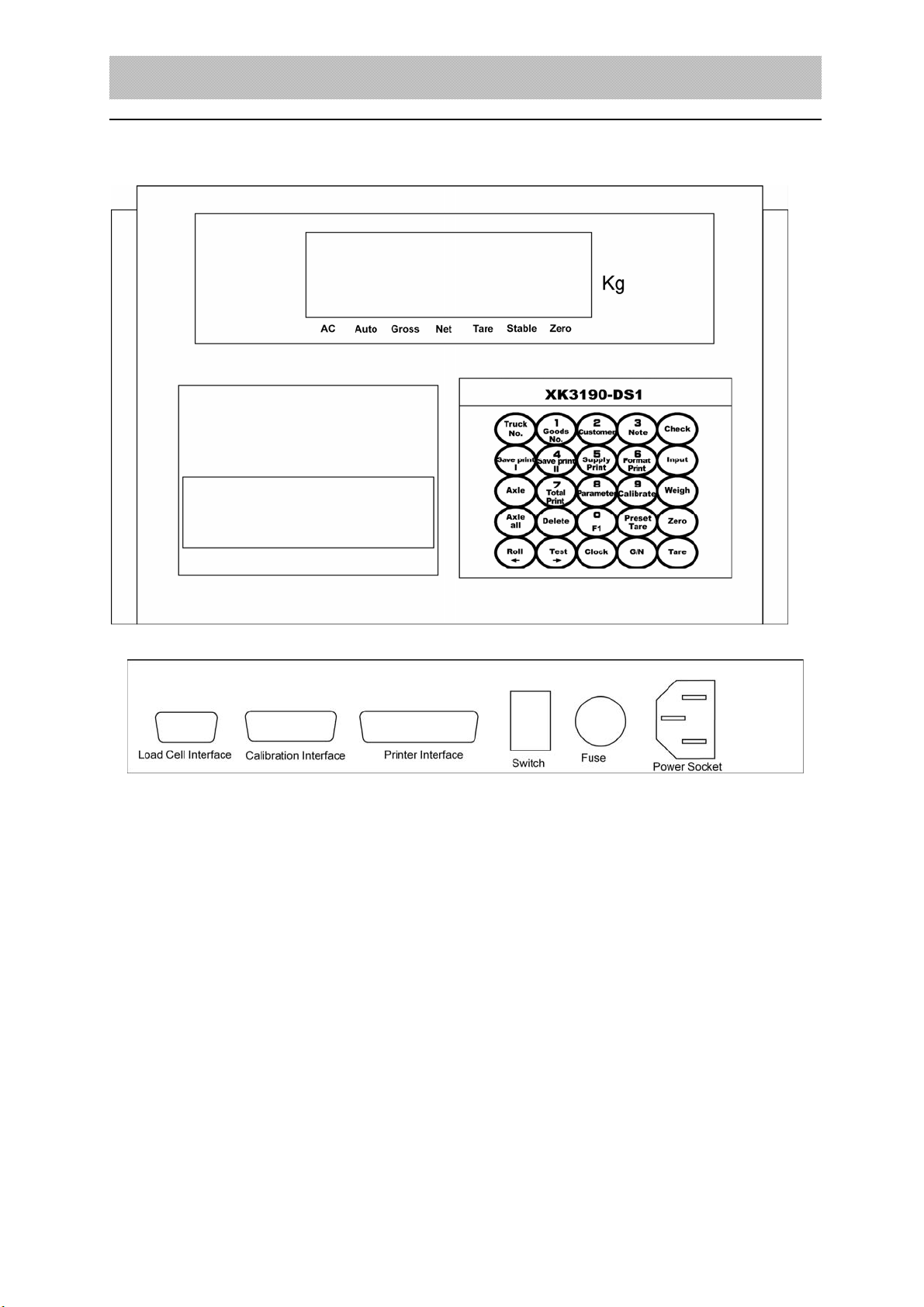
XK3190-DS1
5
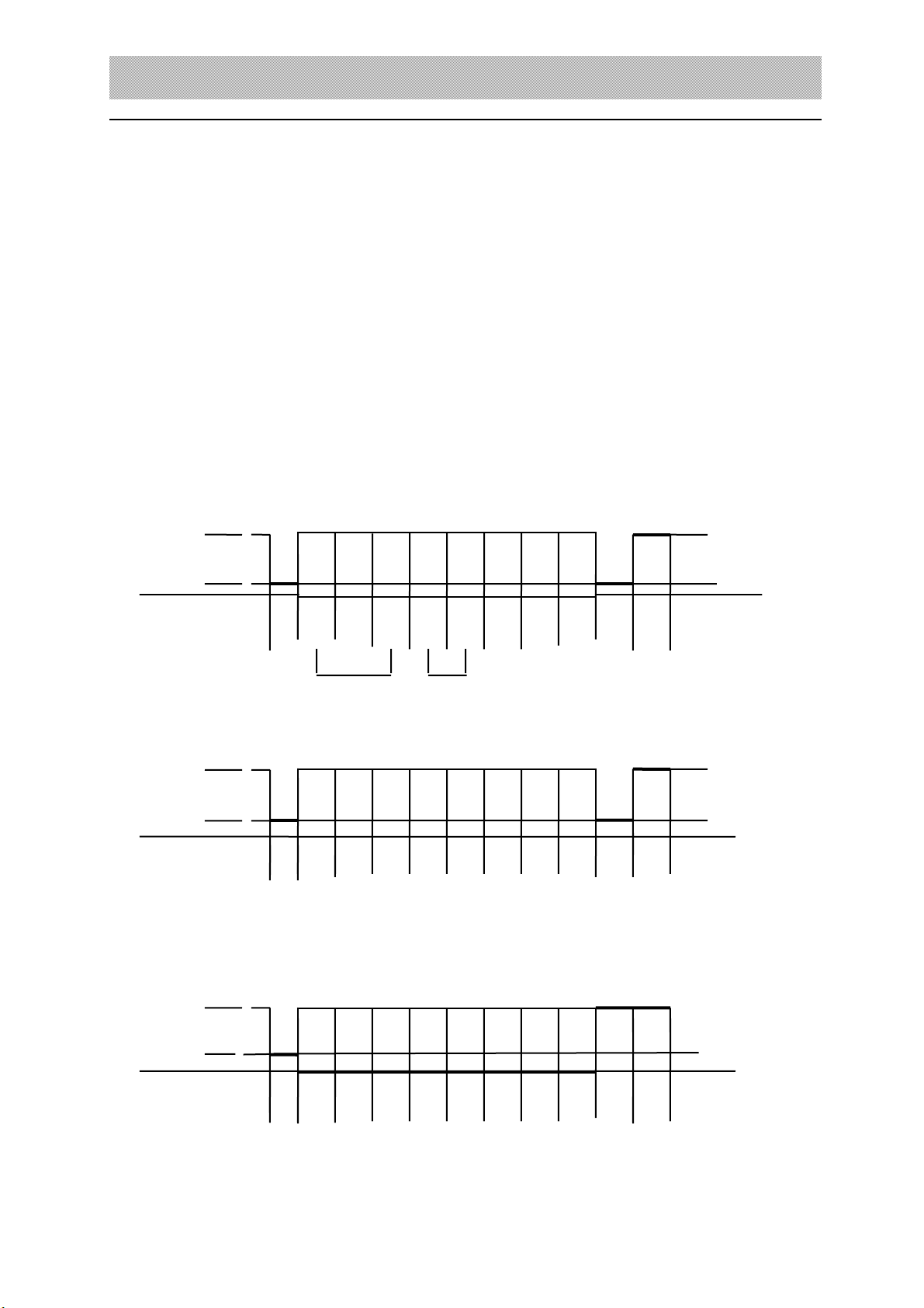
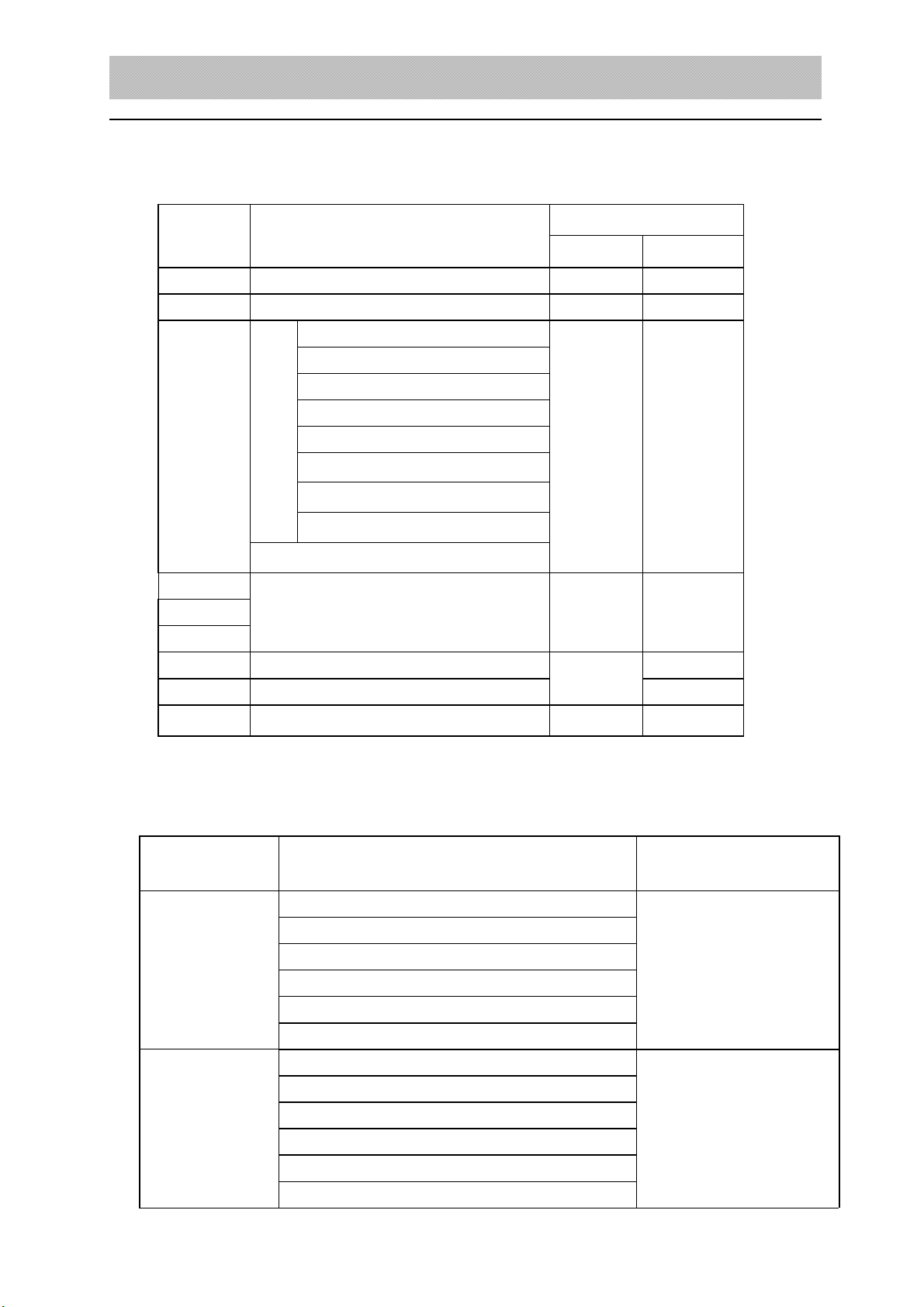
First frame:signal bit is 0
X :D0、D1、D2 – are decimal point ( 0~4 )
Y :D3 — weight symbol( 1-negative、0-positive )
D4 — spare use
G 18~G16:weight data
Second frame:signal bit is0
G15~G8:are weight data
Third frame:signal bit is 1
G7~G0 :weight data
G0~G18:from low to high, 19 binary code composed of weight(net weighit)
5. connect to serial communication interface
▲ !please connect the communication wire to the computer correctly. Damage might be caused
to indicator interface ,computer interface or indicator, computer and relevant devices if they are
connected incorrectly.
▲ !only the person who has the ability of program or relevant computer skill are entitled
to operate the communication with computer, it is necessary to have a professional
person to instruct. Unprofessional person please do not operate to avoid any mistakes.
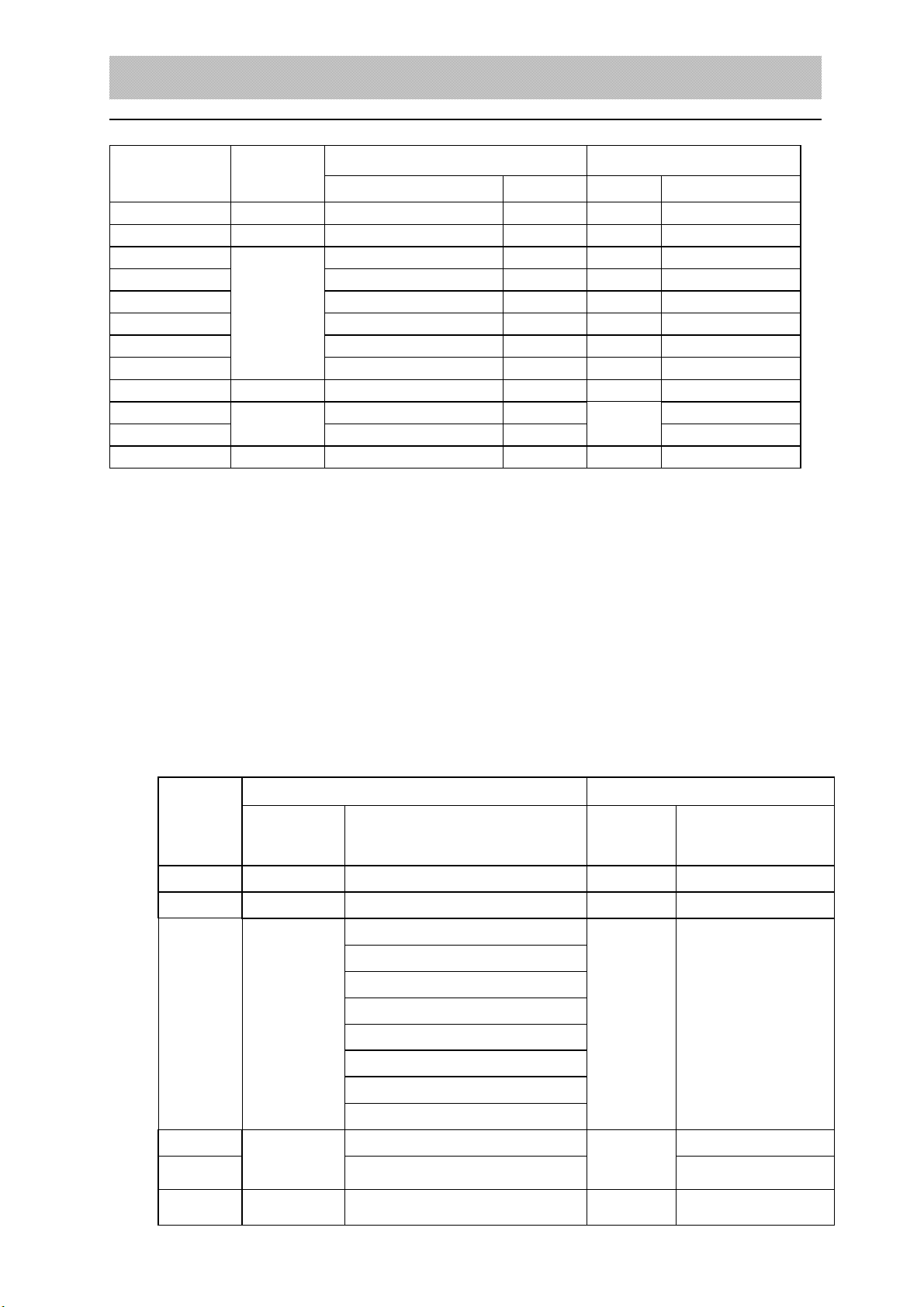
▲ ! communication interface is 15 pin RS232 connector( same with scoreboard interface),
the definition of pin6,7,8(RS232) or pin 1,2,3,4(RS232) are indicated in the following
2-7
(RS422 optional)RS232C communication signal
+TX -TX +R -R RXD TXD signal position
1 2 3 4 5 6 7 8
9 10 11 12 13 14 15
+OUT -OUT
Scoreboard signal output TX(scoreboard RS232output)
(2-7) communication interface definition
1. serial communication instruction:
serial data frame is :n,8,1: 8 data bit, 1 stop bit, no check bit;XK3190-DS1 serial
communication has continuous communication method and command communication method,
serial method has 3 types; through TF parameter (please refer to the chapter 3 for the detail).
Here we just instruct 2 situations when the TF=0,1
(1). Continuous method(TF=0):
The transmission data is the displayed data of the indicator(gross weight). Each data frame
are composed of 12 group data.
The format is as following 2-1: