Techni
ca
l Information DCD90-
180
Lift
Mas
ts
All masts, b
ot
h dupl
ex
a
nd
t
ri
p l
ex
, are
constr
u
cted
on
th e "free visibility prin-
cip
l
e"
and
can
be
su
pp
li
ed
wi
th
the
area
steered
free
-
Lift
system
wh
ic
h, in
term
s of fu n
ctio
n, is
ex
tr
eme
ly re
li
able
a
nd
sec
ur
e.
The
rob
ust mast profil
es
are
of
high
te
ns
il
e st
ee
l, di mensioned fo r minimal
ob
st
ru
ctio n
of
the fie
ld
of
vision a
nd
long
se
rvi
ce
life. Th e lift
cy
linders
are
pos
ition
ed
in
th
e "
dea
d " angl
es
of the
mas
t.
All mast wh
ee
ls are ha rdened a
nd
fitted w ith high quality bearings.
As
sta
nd
ard,
tr
ucks are fitted w ith
th
e
d up l
ex
fr
ee
visibility m
as
t.
Opt
i
ona
l
ex
tr
as:
• Dup l
ex
free visib
ili
ty m
ast
w ith
free-
li
ft
• Trip l
ex
fr
ee
visibili
ty
mast w i
th
free-lift
Duplex free
visibility mast
Dupl
ex
free
visibility
mast
with
free·
lift
Triplex free
visibili
ty
mast
wi
th
free·
lift
90·136,
two free·
lift
cylinders
(150-180, one
ce
ntr
al free-l
ift
cylinder)
Fork Carriages
A number
of
different
mo
dels
of
fork
carr
iages are avai
la
ble, a
ll
of
them
wit
h
exce
ll
ent th
roug
h-vision. The stand
ar
d
mode
l has manua
ll
y
moveab
le fo
rk
s.
Howev
er,
the
majority
of
trucks are
sup pli
ed
with hydraulic side-shift and
fork
posi
tioning.
Op tional extras:
• Fork
pos
itionin
g/s
ide-s
hi
ft
• Fork
pos
itio nin
g/s
id
e-s
hi
ft wi
th
leve
ll
ing
• Fork
pos
itionin
g/s
ide-shift w ith
ce
ntre leve
ll
ing
• Side-shi ft ca
rri
age
• Fork shaft system
• Addi tional types
of
clamp
attac
hm
e
nt
s
• Coil rams for
stee
l
han
dling
Side-
shift
carriage
F
orks
The forks
are
one-pi
ece
for
ged
in
hig h
tens
il
e
stee
l.
The standard
fi
tti ng is
over
h
oo
ks o n the fork
ca
rriage, whilst
hy
dr
auli
ca
ll
y
co
ntr
o
ll
ed forks are fitted
ove
r ro
ll
ers
runnin
g on bearings -fo
ur
up
pe r
ro
ll
ers a
nd
two
l
ower
su
ppo
rt
fo r
eac
h
fo
rk.
For
ease
of
changing
be
t
wee
n
fo
rks
an
d
ot
h
er
a
tt
ac
hments, a fork shaft system
is available , w h
ere
the
fo
rks
are
mo
un
te
d on a separate fo rk holder.
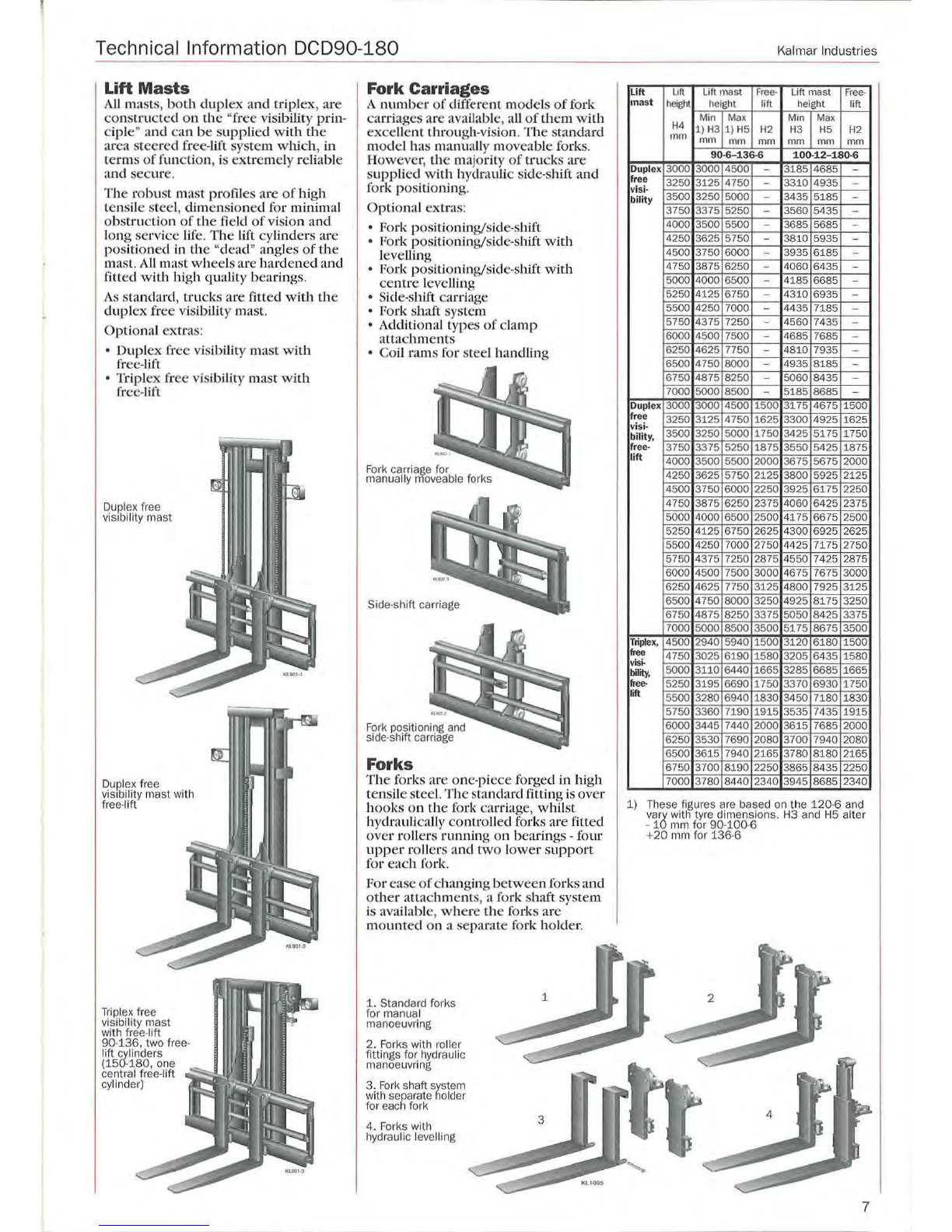
1.
Standard forks
for manual
manoeuvring
2. Forks with roller
fittings for h
yd
raulic
manoeuvring
3.
Fo
rk shaft system
with separate
ho
lder
for each fork
4.
Forks with
hyd
ra
ulic levelling 3
Kalmar Industries
Lift
Uft
Lift mast
Free
· Lift mast
Free-
m
as
t
heigl'lt
heig
ht lift
height
lift
Mi
n
Max
Min
Max
H4
1)
H3
1)
H5
H2
H3 H5
H2
mm
mm mm mm mm
mm mm
90
·6-
136
-6
100-1 2-
180
-6
Dupl
ex
3000 3000 4500 -3185 4685 -
fr
ee
3250 3125 4750 -3310 4935 -
vis
i-
bility 3500 3250 5000 -3435 5185 -
3750 3375 5250 -3560 5435 -
4000 3500 5500 -3685 5685 -
4250 3625 5750 -3810 5935 -
4500 3750 6000 -3935 6185 -
4750 3875 6250 -4060 6435 -
5000 4000 6500 -4185 6685 -
5250 4125 6750 -4310 6935 -
5500 4250 7000 -4435 7185 -
5750 4375 7250 -4560 7435 -
6000 4500 7500 -4685 7685 -
6250 4625 7750 -4810 7935 -
6500 4750 8000 -4935
8185
-
6750 4875 8250 -5060
8435
-
7000 5000 8500 -5185
8685
-
Dup
l
ex
3000 3000 4500 1500 3175 4675 1500
fr
ee
3250 3125 4750 1625 3300 4925 1625
vi
si-
bility, 3500 3250 5000 1750 3425 5175 1750
fr
ee-
3750 3375 5250 1875 3550 5425 1875
lift
4000 3500 5500 2000 3675 5675 2000
4250 3625 5750 2125 3800 5925 2125
4500 3750 6000 2250 3925 6175 2250
4750 3875 6250 2375 4060 6425 2375
5000 4000 6500 2500 4175 6675 2500
5250 4125 6750 2625 4300 6925 2625
5500 4250 7000 2750 4425 7175 2750
5750 4375 7250 2875 4550 7425 2875
6000 4500 7500 3000 4675 7675 3000
6250 4625 7750 3125 4800 7925 3125
6500 4750
8000
3250 4925
8175
3250
6750 4875
8250
3375 5050
8425
3375
7000 5000
8500
3500 5175
86
75 3500
Tripl
ex
, 4500 2940 5940 1500 3120
6180
1500
free 4750 3025 6190 1580 3205
6435
1580
vis~
bi
l
ity
, 5000 3110 6440 1665 3285
6685
1665
fr
ee-
5250 3195 6690 1750 3370
6930
1750
lift 55
00
3280 6940 1830 3450 7180 1830
5750 3360 7190 1915 3535 7435 1915
6000 3445 7440 2000 3615 7685 2000
6250 3530 7690 2080 3700 7940 2080
6500 3615 7940 21
65
3780
8180
2165
6750 3700 8190 2250 3865
8435
2250
7000 3780 8
44
0
23
40 3945
8685
2340
1)
These figures are based on
th
e 1
20·6
and
va~
wi
th
tyre dimensions. H3 and H5 alter
-1 mm for
90-100
·6
+20
mm for 1
36-6
:!"
Ia
~
I
~):1,
2
........
~
f
•
~
..
~
.......
·t:
~
,
~
4 l i
~
~
l
""'
~
......
~
7