KAMEHA KA197 User manual

KAMEHA
Ultra HD Video Wall Processor
MODEL:KA197
VER 1.1

Thank you for purchasing this product
For optimum performance and safety, please read these instructions carefullybefore connecting,
operating or adjusting this product. Please keep this manual for future reference.
Surge protection device recommended
This product contains sensitive electrical components that may be damaged by electrical
spikes, surges, electric shock, lighting strikes, etc. Use of surge protection systems is highly
recommendedinorder to protect andextend the life of your equipment.
Table of Contents
1. Introduction................................................................................................................. 1
2. Features....................................................................................................................... 1
3. Package Contents...................................................................................................... 1
4. Specifications. ............................................................................................................ 2
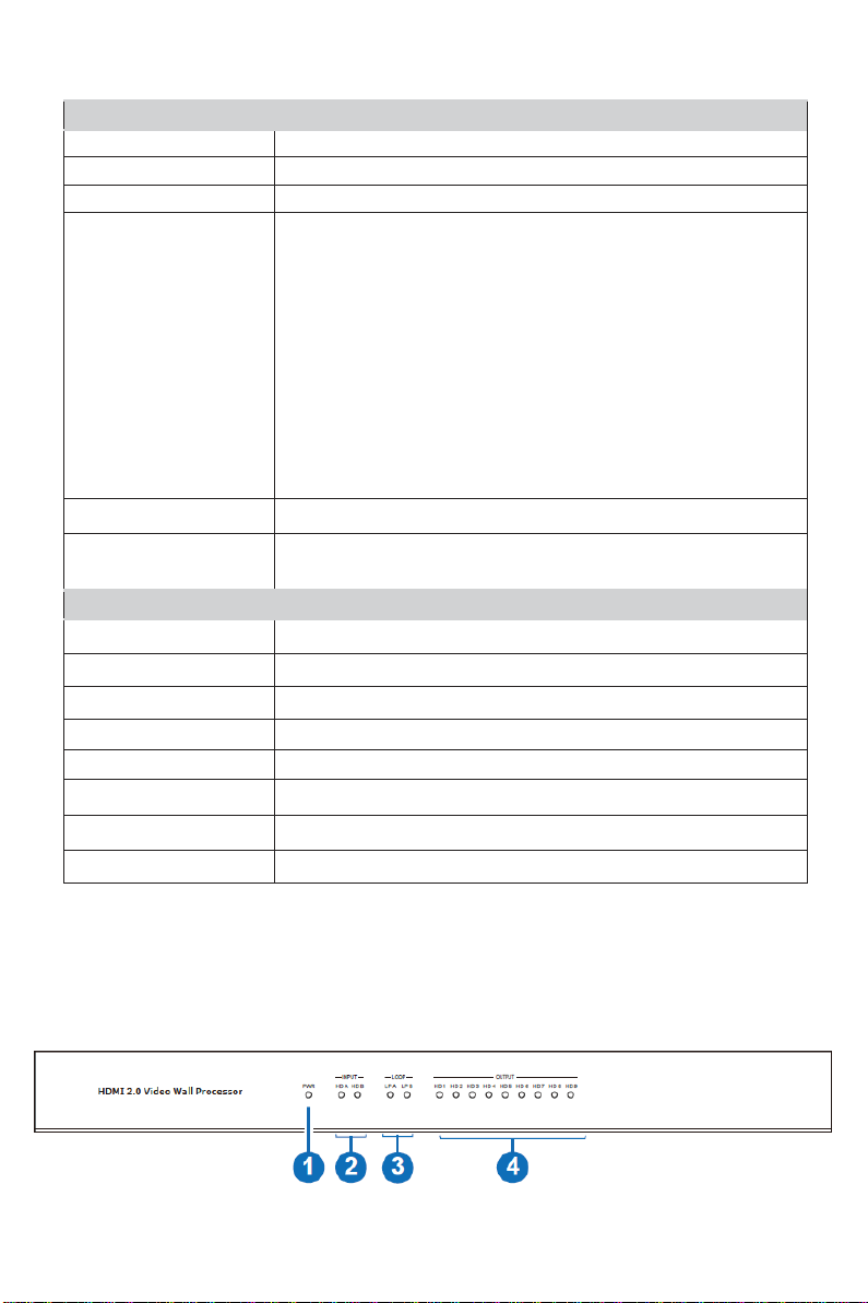
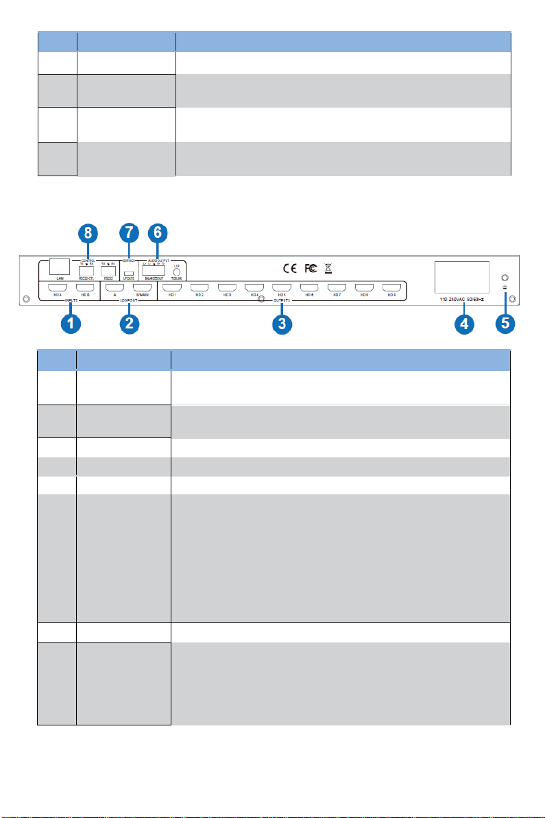
5. Operation Controls and Functions............................................................................. 2
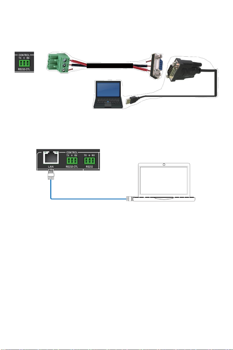
6. RS-232/LAN Control Connection................................................................................ 4
6.1. RS-232 Control Connection. ................................................................................ 4
6.2. Network Control Connection. ............................................................................. 4
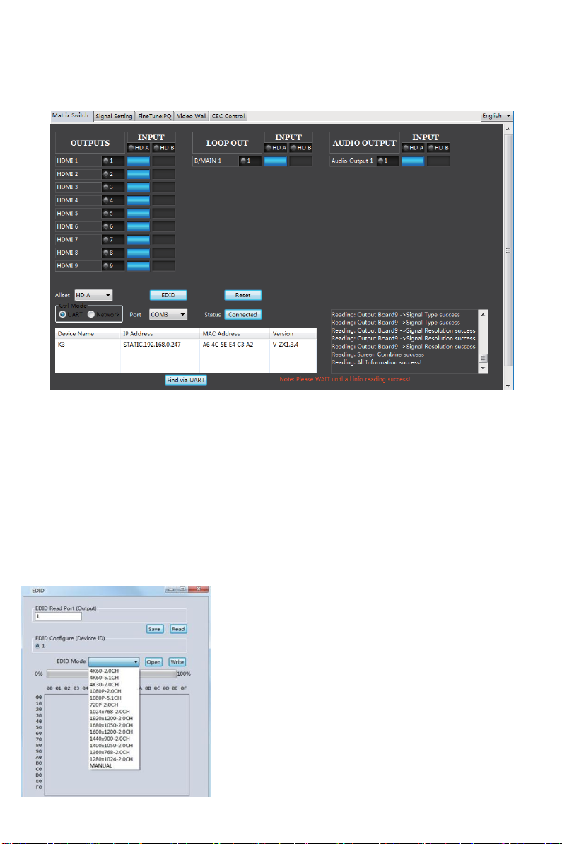
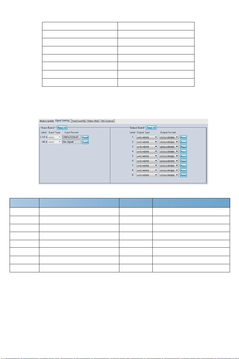
7. PC Tool User Guide. .................................................................................................... 5
8. Safety Instructions....................................................................................................... 11
9. Connection Diagram.................................................................................................. 12

- 1 / 12 -
1. Introduction
This product is an HDMI 2.0 Video Wall controller with 2 HDMI inputs, 2 HDMI loop outputs
and 9 HDMI scaling outputs for video wall processing. The Toslink jack terminal provides
analogue L/R audio and digital SPDIF audio output. 5-pin phoenix jacket provides balanced
L/R audio output. The product also supports RS-232 bypass feature for daisy chain and
cascade connection among different units.
2. Features
☆HDMI 2.0 and HDCP 2.2 compliant
☆Support multi-resolution up to 3840x2160@60Hz video output for video wall
☆Support Bezel Compensation with two modes
☆Support 2 channels HDMI loop out
☆Support PIP on video wall
☆Support 180º rotation
☆Support RS-232 and TCP/IP control
☆Support CEC controlwith displayers byPCTool or commands
3. Package Contents
①1 x Ultra HD Video Wall Processor
②1 xAC Power Cord
③1 x 5-pin Phoenix Connector
④2 x 3-pin Phoenix Connector
⑤1× RS232 to Phoenix Cable
⑥1× CAT6 cable
⑦1× USB to RS232 Cable
⑧1× User Manual

- 2 / 12 -
4. Specifications
Technical
HDMI Compliance
HDMI 2.0
HDCP Compliance
HDCP 2.2/1.4
RS-232
Baud rate: 57600, data bit: 8, Stop bit: 1, no parity
Input Video Formats
1024x768@60, 1280x800@60, 1280x1024@60,
1280x960@60, 1360x768@60, 1366x768@60,
1440x900@60, 1400x1050@60, 1600x900@60,
1600x1200@60, 1680x1050@60, 1920x1200@60,
480p@60, 576p@50, 720p@50, 720p@60, 1080i@50,
1080i@60, 1080p@24, 1080p@25, 1080p@30, 1080p@50
1080p@60, 3840x2160@24, 3840x2160@25,
3840x2160@30, 3840x2160@50, 3840x2160@60,
4096x2160@24, 4096x2160@30, 4096x2160@50,
4096x2160@60
Audio Format
2.0 channel, 5.1 channel, LPCM, Dolby, AC3, DTS
ESD Protection
Human-body Model:
±8kV (Air-gap discharge) , ±4kV (Contact discharge)
Mechanical
Housing
Metal Enclosure
Color
Black
Dimension
430mm (W)×220mm (D)×44mm (H)
Weight
5Kg
Supply Voltage
110-220V AC
OperatingTemperature
0°C ~ 40°C / 32°F ~ 104°F
StorageTemperature
-20°C ~ 70°C / -4°F ~ 158°F
Relative Humidity
10%~50% RH (non-condensing)
5. Operation Controls and Functions
Front Panel

No.
Name
Function Description
1
INPUTS
HDMI signal input ports, connect to HDMI source devicesuch
as DVD or PS4 with HDMI cable.
2
LOOP OUT
HDMI signal loop out ports. Loop out HDMI A/B signal to
downstream. It can be configured byRS-232 command.
3
OUTPUTS
HDMI signal scaling output for video wall.
4
110-240VAC
110-240VAC power input port.
5
GND
Ground the product housing.
6
AUDIO OUTPUT
TOSLINK:
•Analog L/R audio output
3.5mm Stereo Jack. 20Hz ~ 20kHz, 1.5Vrms max
•Digital SPDIF audio output
BALANCED OUT: Balanced audio output port. 5-pin phoenix
connector, 20Hz ~ 20kHz, 1.5Vrms max.
BALANCED OUT: Balanced audio output port. 5-pin phoenix
connector, 20Hz ~ 20kHz, 1.5Vrms max.
7
SERVICE
Firmware update port.
8
CONTROL
RS232: Bypass RS232-CTL commands to next unit.
RS232-CTL: External RS-232 control, Baud Rate: 57600
Data Bits:8, Parity: None Stop Bits:1
LAN: Network port for TCP/IP control. Connect to an active
Ethernet link with an RJ45 cable.
No.
Name
Function Description
1
Power LED
Power LED will be on when the unit is powered on.
2
INPUT LED
TheLEDwillbeonwhenthecorrespondingHDMIinputportis
connected to active HDMI source device.
3
LOOP LED
TheLEDwillbeonwhenthecorresponding LOOPOUT portis
connected to HDMI display device.
4
OUTPUT LED
(1-9)
TheLEDwillbeonwhenthecorrespondingHDMIoutput portis
connected to HDMI display device.
Rear Panel
- 3 / 12 -

- 4 / 12 -
6. RS-232/LAN Control Connection
6.1 RS-232 Control Connection
The product supports RS-232 control. Connect the RS232-CTL port of the product to a PC via
a serial cable, as shown in the following figure:
TX
Ground
RX
3-pin Phoenix Connector
RS-232
RS-232 to USB cable
PC
6.2 Network Control Connection
The product also supports Network control. Connect the LAN port of the product to a PC via
an UTP cable, as shown in the following figure:
PC

- 5 / 12 -
7. PC Tool User Guide
The PC tool is an installation-free control software that supports both UART and network
control. It consists of five parts: Matrix Switch, Signal Setting, FineTune:PQ, Video Wall
and CEC Control. The UI is as follows:
■Matrix Switch Page
1. You can select UART (with RS232 cable) or Network to connect device, baud rate is
57600 bps.
2. Select input source for each scaling output port.
3. “AllSet”function: Select HD A or B input source to all the scaling output.
4. Select input source for B/MAIN output port.
5. Select audio source for balanced audio output and Mini Toslink output.
6. Reset: The PC tool supports reset system to recover to factory configuration.
7. EDID Control: Click the “EDID”button on the Matrix Switch page, there will be a pop-up
EDID control window.
a) Read each scaling output port downstream EDID and
save as a BIN file.
b) Open an existing EDID file and write to the HDMIA
and B input port as Manual EDID.
c) Select predefined EDID and write to HDMIA and B
input ports.

- 6 / 12 -
Predefined EDID option is as below:
4K60-2.0CH
1920x1200-2.0CH
4K60-5.1CH
1680x1050-2.0CH
4K30-2.0CH
1600x1200-2.0CH
4K30-5.1CH
1440x900-2.0CH
1080P-2.0CH
1400x1050-2.0CH
1080P-5.1CH
1360x768-2.0CH
720P-2.0CH
1280x1024-2.0CH
1024x768-2.0CH
Manual
■Signal Setting Page
User can read the resolution of each input port and set the resolution of each scaling output.
Available output resolutions:
No.
Output Resolution Setting
No.
Output Resolution Setting
1
3840x2160p 60Hz
9
1440x1050 60Hz
2
3840x2160p 50Hz
10
1366x768 60Hz
3
3840x2160p 30Hz
11
1360x768 60Hz
4
3840x2160p 25Hz
12
1280x1024 60Hz
5
1920x1200 60Hz
13
1280x768 60Hz
6
1920x1080p 60Hz
14
1280x720p 60Hz
7
1920x1080p 50Hz
15
1280x720p 50Hz
8
1600x1200 60Hz
16
1024x768 60Hz
Note: 3840x2160 25/30Hz can only be used for standalone display, not for video wall.

- 7 / 12 -
■FineTune: PQ Page
You can read and set the Brightness/Contrast/Saturation/Sharpness of each output.
Note: Suggest always use the default setting 50/50/50/50. Do not change the default
settings without special conditions; If there is a problem after changing, click “Reset”to
return to the factory settings.
■CEC Control Page
If Auto Power On is enabled, every time when the product is turned on, it will turn on all
displayers which are connected to it.
The product supports CEC function, including Power on/off, Volume+/-, Mute/Unmute.

- 8 / 12 -
■Video Wall Page
This page is used to configure a group of outputs to function as a video wall.
1. Use the Video Wall Setting controls to change how the displays are arranged on the Video
Wall page:
a. Adjust the Rows and Columns sliders to change the displayed screen arrangement to
permit proper Drag-and-Select of the desired screens for the video wall.
b. Change the Available slider to set how many outputs will be used for the Video Wall.
c. Click the “Set”button to change the Screen configuration.
2. Use the left mouse button to drag-select the screens that will be set for video wall mode.
The selected screens will be shown as bright blue.
3. Use the right mouse button to open a menu.
4. Select “Screen Stitching” from the menu to program the video wall mode. The selected
screens will now be shown as bright green.
5. To change the displayed image: either use the methods detailed inthe section Controlling
the Matrix Switcher right-click to open the pop-up menu and select the desired input from
the “Input Select”menu option.

- 9 / 12 -
6. Repeating steps 2 ~ 5 above with a different set of outputs allows the creation of a second
video wall. However, changing the Rows, Columns and Available sliders will automatically
delete the current video wall set up when the “Set”button is clicked. The following example
shows a more unusual video wall set-up of two video walls with 1x3 and 2x2 configurations:
Video Wall Context Menu
Right clicking on anyof the screen icons will display the following context menu:

- 10 / 12 -
Screen Stitching
This option connects the selected screens into a video wall configuration.
Cancel Stitching
Return the VideoWall configuration to normal outputs.
Screen x –
Cancel Stitching
Remove the single screen x from the video wall to allow the displaying
another full frame image within the video wall configuration, as shown in
this example:
Input Select
Use the sub-menu to select the input to display on the video wall or the
secondary input image shown in the above example.
Output Select
This option is only available for any screen that is not assigned to a
video wall mode.
Output Type
This option is only available for any screen that is not assigned to a
video wall mode.
Output Format
This option is only available for any screen that is not assigned to a video
wall mode. It allows setting of the output resolution for the selected
screen output.
Mirror
Four sub options: OFF (default ), H ( Horizontal ), V ( Vertical ) , H+V
When select H+V, you can make 180º rotation with the selected screen.
Test Pattern
WhenTest Pattern is enabled, the output will display Color Bar pattern.
Bezel Setting
The Bezel Setting section allows the entry of values to compensate for the display bezel
thickness. These values may be entered either as pixels (Type A) or as millimetre (Type B).
Type A Bezel Settings
The image size will be adjusted to allow for the number of pixels entered in each of the
entryboxes. Click the “Set”button to view the effect of the new values.
Type B Bezel Settings
The image size will be adjusted to allow for the Inner and Outer display dimensions as
entered in each of the entryboxes. Click the “Set”button to view the effect of the new values.

- 11 / 12 -
Bezel Compensation
The following images demonstrate the effect of not having bezel compensation and what a
correctly configured bezel compensation settings should produce:
No Bezel Compensation Correct Bezel Compensation
Layout Save/Load
The Save Scene/Layout and Load Scene/Layout buttons allow a video wall configuration to
be saved or recalled at any time. Up to 10 configurations, each with their own name can be
saved or recalled. When saving, each Scene can optionally be given a name to identify that
video wall scene setup.
8. Safety Instructions
To ensure reliable operation of this product as well as protecting the safety of any person
using or handling this device while powered, please observe the following instructions.
1. Do not operate either of this product outside the specified temperature and humidity range
given in the above specifications.
2. Ensure there is adequate ventilation to allow this product to operate efficiently.
3. Repair of the equipment should only be carried out by qualified professionals as these
products contain sensitive devices that may be damaged by any mistreatment.
4. Only use this product in a dry environment. Do not allow any liquids or harmful chemicals
to come into contact with these products.

- 12 / 12 -
9. Connection Diagram
Control System Speakers
CONTROL
SERVICE AUDIO OUTPUT
TX RX TX
RX L+ L- R+ R-
L / R
LAN R 32-CTL
RS232 UPDATE
BALANCE
D OUT TOS
L
I
NK
HD
A HDB A B/MAIN HD 1
HD 2 HD 3
HD 4 HD 5 HD 6
HD 7 HD 8 HD 9
INP UTS
S
2
DVD Player
Lap Top
LOOP
OUT
O U TP U TS
110-240VAC 50/60Hz
TV TV
TV x 9
HDMI
AUDIO
CAT
Table of contents
Other KAMEHA Media Converter manuals
Popular Media Converter manuals by other brands

Transition Networks
Transition Networks C/RS232-CF-01 user guide

Texas Instruments
Texas Instruments TPS53319EVM-136 user guide

VigilLink
VigilLink VLSP-AD14H20 user manual

Carelink
Carelink CL-MCSFP-16 installation guide

YASKAWA
YASKAWA PROFINET V1000 quick start guide

Patton electronics
Patton electronics 2020P Installation and operation manual

Frauscher Sensortechnik GmbH
Frauscher Sensortechnik GmbH WSC001 Technical documentation

Shenzhen Ousent Technologies CO.,LTD
Shenzhen Ousent Technologies CO.,LTD OS-MC12-SFP user manual

CYP
CYP CSLUX-300 Operation manual

iScan
iScan VP50 owner's manual

Aiwa
Aiwa Pro Enigma MI-X450 user manual

Telecom Behnke
Telecom Behnke 20-9594C instructions