Kamera Werk Dresden CMOS User manual

Manual
CMOSIndustrialCamera
LOGLUXi5CL
Version1.08 (July2004)

Version 1.08 (04/07)Manual: CMOSIndustrialCameraLOGLUXi5
Page2of46KAMERAWERKDRESDENGmbH
TableofContents
LISTOFFIGURES..............................................................................................................................................3
LISTOFTABLES ...............................................................................................................................................3
REVISIONINDEX...............................................................................................................................................3
INTRODUCTION..............................................................................................................................................4
THE CMOS INDUSTRIALCAMERA LOGLUXI5CL..............................................................................................5
TheCMOSlarge-areasensorIBIS5...........................................................................................................5
The dynamic(contrast)rangeoftheIBIS5sensor...................................................................................6
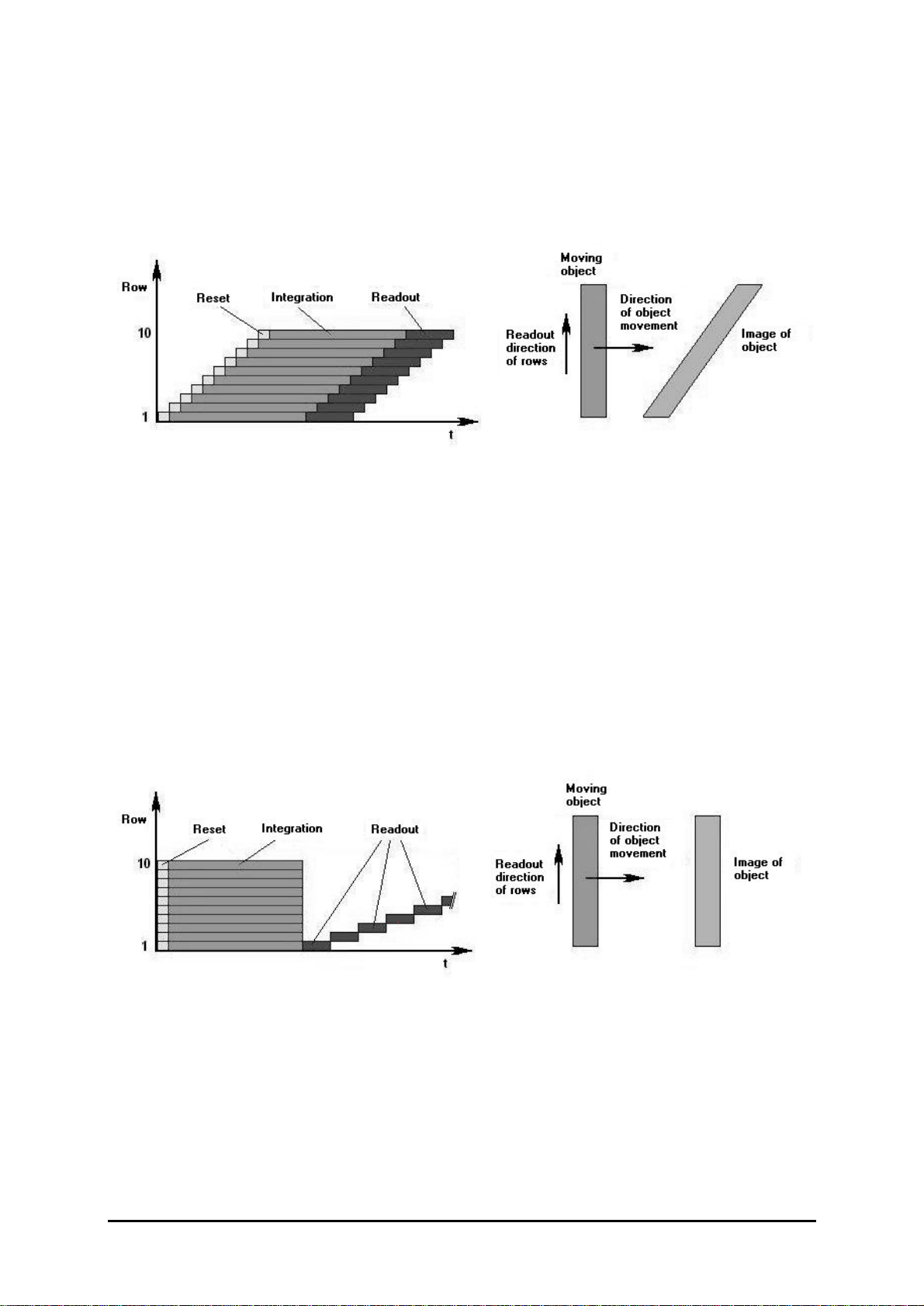
The shuttermodesoftheIBIS5sensor...................................................................................................8
The look-up tables (LUTs)oftheCMOSindustrialcameraLOGLUXi5CL................................................9
TheCameraLink™imagedatainterface......................................................................................................9
THECOMPLETE LOGLUXI5CLSET CAMERASYSTEM.......................................................................................9
OPTIONALACCESSORIES...................................................................................................................................9
OPERATIONOFTHECOMPLETELOGLUXI5CLSETCAMERA SYSTEM................................................10
SYSTEMREQUIREMENTS .................................................................................................................................10
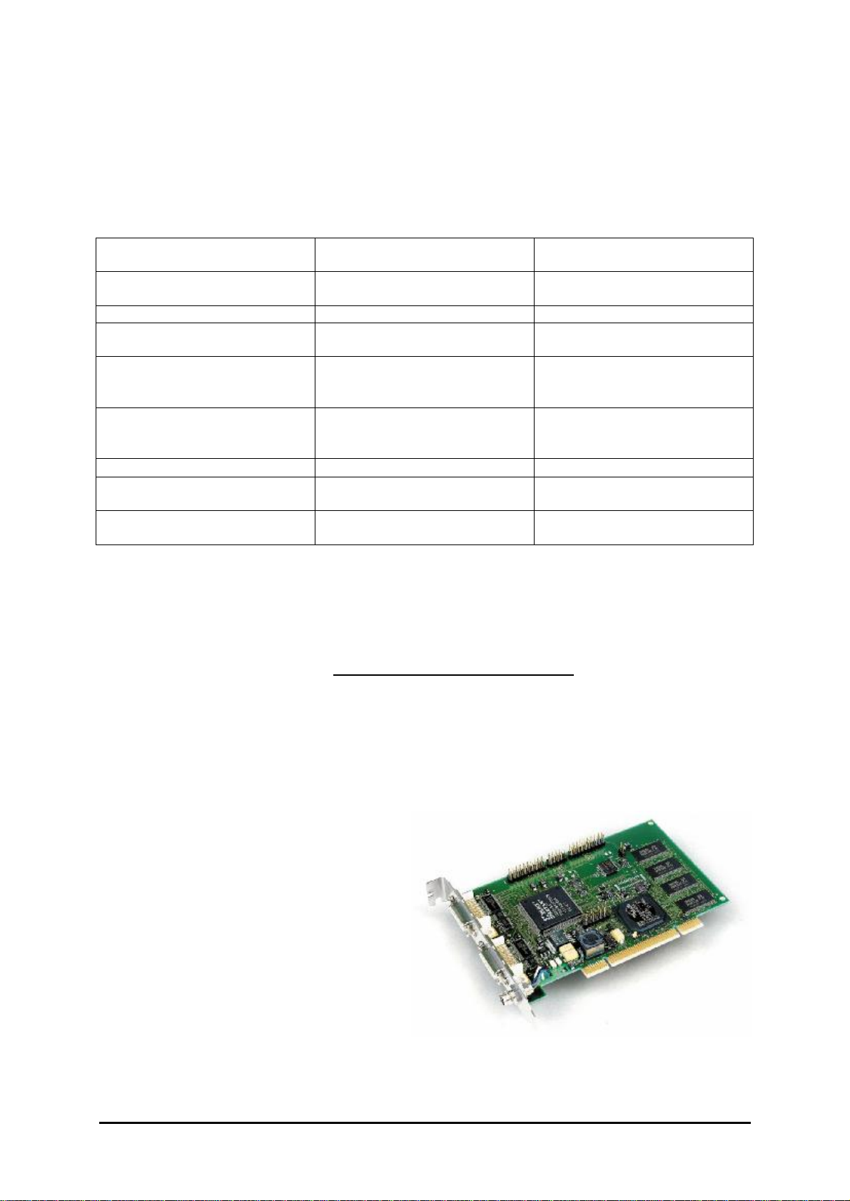
INSTALLATION OFTHE CAMERALINK™PC PLUG-IN CARD MATRIXVISION MVTITAN-CL...........................................10
INSTALLATION OFTHE CMOS INDUSTRIALCAMERA LOGLUXI5CL....................................................................11
INSTALLATION OFTHE LOGLUXLUXWARECONFIGURATION TOOL.......................................................................11
DESCRIPTIONOFTHELOGLUXLUXWARECONFIGURATIONTOOL......................................................12
THEPHILOSOPHY...........................................................................................................................................12
THESTARTMENU...........................................................................................................................................13
THECONFIGURATIONMENU..............................................................................................................................14
THE 'CAMERAGLOBALS' MENU .........................................................................................................................15
THE 'PROFILEGLOBALS' MENU .........................................................................................................................16
THEUSER PROFILEPARAMETERS......................................................................................................................17
The 'Region ofInterest'profilemenu ....................................................................................................17
The ‚Trigger‘profilemenu ....................................................................................................................18
The ‚Switchport‘profilemenu...............................................................................................................19
The ‚Sensor‘profilemenu ....................................................................................................................21
The ‚Outputdata‘profilemenu .............................................................................................................22
THE 'SPECIAL FUNCTION' MENU........................................................................................................................23
THE 'LOOK-UP TABLEX' MENU..........................................................................................................................24
THE 'TERMINAL' MENU ....................................................................................................................................25
THE 'FIRMWARE' MENU ...................................................................................................................................26
THE 'FRAMEGRABBER' MENU............................................................................................................................27
DESCRIPTIONOFTHELOGLUXI5CLREGISTERSET..............................................................................29
FUNCTION GROUP ‚CAMERACONFIGURATION‘.....................................................................................................29
FUNCTION GROUP ‚CAMERAPROFILES‘..............................................................................................................30
FUNCTION GROUP ‚WORKINGPARAMETERS‘.......................................................................................................36
FUNCTION GROUP ‚LUT PROGRAMMING‘............................................................................................................37
GLOSSARY...................................................................................................................................................38
TECHNICALSPECIFICATION.......................................................................................................................40
TECHNICALDATAOFTHE LOGLUX I5CL(SURVEY)...........................................................................................40
PINASSIGNMENTSOFTHE LOGLUX®I5CL......................................................................................................40
PINASSIGNMENTOFTHESPLITCABLEFOR THE LOGLUX®I5CL..........................................................................40
WIRINGOFTHE LOGLUX®I5CL TRIGGER INPUT ...............................................................................................41
WIRINGOFTHE LOGLUX®I5CL SWITCH OUTPUTS............................................................................................41
NOTES ON UPDATINGTHEFIRMWAREFOR THE LOGLUX®I5CL CAMERA ...............................................................41
CHOOSINGALENSFOR THE LOGLUX®I5CL....................................................................................................44
MATCHINGTHEFLANGEFOCALLENGTH OFALENSWITHTHE LOGLUX®I5CL........................................................44
FREQUENTLYASKEDQUESTIONS.............................................................................................................44
ADDINGANON-SUPPORTED CAMERALINK™FRAMEGRABBER.................................................................................45
USINGSOFTWARE-SUPPORTED FRAMEGRABBERSON THESERIAL COM PORTOFTHE LOGLUXI5CL CAMERA..........46

Manual: CMOSIndustrialCameraLOGLUXi5Version 1.08 (04/07)
KAMERAWERKDRESDENGmbHPage3of46
Listoffigures
FIGURE 1: FRONTAND REAR VIEWOFTHE CMOS INDUSTRIALCAMERALOGLUXI5CL............................................5
FIGURE 2:BLOCKDIAGRAMOFTHE CMOS INDUSTRIALCAMERA LOGLUXI5CL.......................................................5
FIGURE 3: EXAMPLEOFAVERYHIGHIMAGECONTRASTRANGE...................................................................................6
FIGURE 4:WORKINGPRINCIPLEOFTHEROLLING/CURTAIN SHUTTER AND THEIMAGINGOFMOVINGOBJECTS ......................8
FIGURE 5:WORKINGPRINCIPLEOFTHECENTRAL/SNAPSHOTSHUTTER AND THEIMAGINGOFMOVINGOBJECTS...................8
FIGURE 6: MATRIXVISION MVTITAN-CLPC PLUG-IN CARD...................................................................................10
FIGURE 1: VIEWOFASPLITCABLE ....................................................................................................................131
FIGURE 8: THESTARTMENU ...............................................................................................................................13
FIGURE 9: THECONFIGURATIONMENU..................................................................................................................14
FIGURE 10: THE 'CAMERAGLOBALS' MENU ...........................................................................................................15
FIGURE 11: THE 'PROFILEGLOBALS' MENU ...........................................................................................................16
FIGURE 12: THE 'REGION OF INTEREST' PROFILEMENU...........................................................................................17
FIGURE 13: THE ‚TRIGGER‘ PROFILEMENU............................................................................................................18
FIGURE 15: THE ‚EXPOSURE‘ PROFILEMENU.........................................................................................................20
FIGURE 16: THE ‚SENSOR‘ PROFILEMENU ............................................................................................................21
FIGURE 17: THE ‚OUTPUTDATA‘ PROFILEMENU.....................................................................................................22
FIGURE 19: THE 'LOOK-UPTABLEX' MENU ............................................................................................................24
FIGURE 20: THE 'TERMINAL' MENU.......................................................................................................................25
FIGURE 21: THE 'FIRMWARE' MENU......................................................................................................................26
FIGURE 22: THE 'FRAMEGRABBER' MENU..............................................................................................................27
Listoftables
TABLE 1: LISTOFCAMERACONFIGURATIONINSTRUCTIONS .....................................................................................28
TABLE 2: PARAMETER NOTATION FOR CAMERACONFIGURATION ..............................................................................28
TABLE 3: REGISTERSOFTHEFUNCTION GROUP 'CAMERACONFIGURATION'...............................................................29
TABLE 4: REGISTERSOFFUNCTION GROUP 'CAMERAPROFILES'..............................................................................31
TABLE 5: LISTOFREGISTER INITIALVALUES OFFUNCTION GROUP 'CAMERACONFIGURATION'........................................32
TABLE 6: REGISTERSOFFUNCTION GROUP 'WORKINGPARAMETERS'.......................................................................36
TABLE 7: REGISTERSOFFUNCTION GROUP 'LUT PROGRAMMING.............................................................................37
Revisionindex
VersionChanges,supplements,etc.
1.05(May`04) -Updateof theLuxWareV. 1.1.3programwindowdumps
-Additionofchapter‚Frequentlyaskedquestions‘+instructionsforINImodifications
1.06(June`04) -Updateof theLuxWareV. 1.2.1programwindowdumps
-Additionofchapter‚The‚Switchport‘profilemenu‘
-Completerevisionofchapter‚Functiongroup ‚Cameraprofiles‘‘,integration ofthetriggerand
switching moduleinthefirmware-version camera[V.1.22(uC),V.1.004 (FPGA)](renaming
and addition ofregisters,address relocations,etc.)
-Additionoffigure‚Viewofasplitcable‘inchapter‚InstallationoftheCMOSindustrialcamera
LOGLUX®i5CL‘andofitem‚LOGLUX®i5CLsplitcablepinassignment‘inchapter‚Technical
specifications‘
-Additionofitem‚TechnicaldataoftheLOGLUX®i5CL(survey)‘inchapter‚Technical
specifications‘
1.07(July`04) -Additionofitem‚Noteson theupdateoftheLOGLUX®i5CLfirmware‘inchapter‚Technical
specifications‘
1.08(July`04) -Updateof theLuxWareV. 1.2.4programwindowdumps
-Additionofchapter‘The‚Specialfunction’profilemenu’’
-Modificationinchapter’The‚Framegrabber’profilemenu’(additionofuserinitialsetting of
framegrabbertime-outforcontrolledimagecaptureviaexternaltriggersignal,functional
extension bysaving ofimagesequencesand renamebuttonlabel‚Sequence’instead of ‚AVI’)

Version 1.08 (04/07)Manual: CMOSIndustrialCameraLOGLUXi5
Page4of46KAMERAWERKDRESDENGmbH
Introduction
Thismanual describesthe installation and functionsoftheCMOSindustrial cameraLOGLUXi5CL
made byKAMERAWERKDRESDENGmbH,aswell asthe softwareand hardwarecomponents
whichareadditionallyrequired foracamerasystem.
The belowchapterswill enablethe usertooperateacamerasystemincluding aCMOSindustrial
cameraLOGLUXi5CL,and tofullyexploitthecamerafunctionsbyapplying the supplied LOGLUX
LuxWareconfiguration tool.Furthermore,the commandsreferred tohereinpermitthe ambitious
programmertoconfigurethe cameraat CMOSsensorregisterlevelbymeansof the integral terminal.
Note: Thismanual wasdrawn up withutmostcare.However,sincethe unitisconstantlybeing
improved,no guarantycan be given thattheinformation iscompleteand correctatany
time.Wehavemade greateffortstoprovide you withaperfectproductbutinviewofthe
numerouscomputerconfigurationsitisimpossibletoguarantee thatyourcomputeroryour
application workstrouble-free inallconfigurationsand combinations.
Wecannot guarantee that aspecificapplication purposeisserved.Withinthe framework of
the statutory regulations,anyliabilityfordirectdamage,indirectdamage and third-party
damage resulting fromthe purchaseoroperationofaLOGLUXi5CL CMOSindustrial
cameraisexcluded.Liabilityincasesofintentand gross negligenceremainsunaffected
therefrom.Inanycase, ourliabilityislimited tothepurchasepriceofthe unit.
Thismanual isprotected bycopyright.Allrightscreated thereby,inparticulartherighttotranslate,reprintorlecture,touse
figuresortables,tobroadcast,microfilmorreproducethecontentsorpartsthereof inanyotherwayortostoreitpartlyorwholly
in dataprocessingsystems,arereserved.Alsoin individualcases,the manual orpartsthereofarepermitted tobereproduced
onlywithinthescopeof theCopyrightActof theFederalRepublicof GermanyofSeptember9,1965asamended.Asarule,a
fee ischargedforanyreproduction.Violationsaresubjecttothepenalprovisionsof theCopyright Act.
Copyright KAMERAWERK DRESDENGmbH2004
Even if noexpress referenceismadethereto, theuseorreproductionofmodel ortradenamesmentioned in thismanual does
notjustifytheassumption that suchnamesarefree nameswithinthemeaningof thetrademarkand proprietaryrightsthat could
beused byeveryone.
Whereverdirectorindirectreferenceismadeinthismanual toacts,regulationsorstandards(e.g.DIN,VDI, VDE),KAMERA
WERKDRESDENGmbHcannotguarantee thattheyarecorrectandup-to-date.Werecommendtoconsultthecomplete
regulationsorstandardsasamendedforthespecificownapplication.
KAMERAWERK DRESDENGmbH
Bismarckstrasse56
D-01257 Dresden
Phone(0351)2806 0
Fax (0351)2806 392
eMail info@kamera-werk-dresden.de
Web www.kamera-werk-dresden.de

Manual: CMOSIndustrialCameraLOGLUXi5Version 1.08 (04/07)
KAMERAWERKDRESDENGmbHPage5of46
TheCMOSindustrial cameraLOGLUXi5CL
The CMOSindustrial cameraLOGLUXi5CL isone ofthe latestand most modernproductsfromthe
‚industrialimage processing CMOScamera‘ range of KAMERAWERKDRESDENGmbH.
The cameracan be considered alogically
consistentdevelopmentofthe well-known,
universallyapplicablepredecessormodel
LOGLUXHDRC4.
Mainfeaturesof the CMOSindustrialcamera
LOGLUXi5CL:
•CMOScamerawithfree pixel selection
(progressivescan)and CameraLink™data
interface
•Approx.36 images/second (fullframe),higherrateswhen asmallerframesizeisused (up to
approx. 1500 images/second arepossible)
•Resolution: 1280x1024 pixels,10-bitgreyscale
•>100 dBcontrast/dynamicrange
•Digital image datainterface
•Possibilitytopre-process the image databymeansof the integralLUTs(look-up tables)
•Spectral working range from400nmto1000nm
•Sturdycontinuouslycast aluminumcasing withC-type lensmount
•Possibilitytoconfigureand controlthe camera,and transferthe image data,bymeansofacable
connected tothe host system(PC).
The CMOSindustrial cameraLOGLUXi5CL isbased on
auniversalhardwareconceptwhichcomprisesaCMOS
large-area image sensor(FS),pre-processing unit(VV),
controller(SE),datainterface(DS) and operating voltage
supply(SV).
Inthe pre-processing unit,the image datafromthe CMOS
image sensorcan be linked up inrealtimewithone of
three possibleuser-specificLUTs(look-up tables).Inthe
process,the image datacan be replaced byfunction
values,e.g.arithmeticoperations.By defining agreyscale
thresholdinaLUT, forexample,the cameracan be made
todeliverthe 'suitable'image materialforaedge
recognition.
The camerafirmwarecan be updated via an additionalRS232 interface.Voltage issupplied froma
plug-type powersupplyunit(24V/6W;comeswiththe unit)oran SPSDINrail powersupplyunit(24V
±10%).
The CMOSlarge-area sensorIBIS5
The sensorelementused inthe CMOSindustrialcameraLOGLUXi5CL isatype IBIS5CMOS
image sensormade byFillfactory (Mechelen/Belgium).
It isaphoto-optical componentofthe latestCMOSimage sensorgeneration.Being atypicalSOC
(system-on-chip),the sensordoesnotonlyaccommodatethe sensor(pixel)elementsproper,butalso
allperipheral analog and digital componentsrequired todeliveranoise-corrected 10-bitgreyscale
value asan output signal.
Mainfeaturesofthe sensorareitshigh resolution of1280 x1024 pixels(XGAresolution),the wide
dynamic(contrast)range ofup to100dB,the integrated FPN(fixed patternnoise)correction ofthe raw
image data,and twoshuttermodes(rolling/curtain shutter and synchronous/snapshot shutter).
Asregardsthe conversion process, the IBIS5isan integrating, photo-opticalsensor.
Formoretechnicaldatapleaserefertothe latestIBIS5datasheet.
The following paragraphsdescribe selected functionsofthe sensor.Understanding thesefunctionsis
imperativetothe properuseofthe variousfunctionalunits.
Figure2:Front and rearviewoftheCMOSindustrial camera
LOGLUXi5CL
Figure3: Block diagramof theCMOS
industrialcameraLOGLUXi5CL
FS VV DS
SV SE

Version 1.08 (04/07)Manual: CMOSIndustrialCameraLOGLUXi5
Page6of46KAMERAWERKDRESDENGmbH
The dynamic(contrast)range ofthe IBIS5sensor
Incontrastto,say,CMOSsensorsformultimediaapplications,the IBIS5hasaverywide dynamic
(contrast)range.Thisparameterdescribesthe sensor'scapabilitytoshowbothverybrightand very
dark image partsinthe activeframe.The figureshowsaCD ROMwhosesurfaceisdiagonallylitbya
lampfromthe front,withthe LOGLUXi5CL setforanormal(approx.67dB) and extended (approx.
100dB) contrast range, respectively.
Figure4: Exampleof averyhigh imagecontrast range
Inthe photoon the leftside,neitherthe manufacturer'snamenorthe storage capacitynorthe
maximumwritespeed can be read.Onthe rightside,thisinformation can beread withoutdifficulty,
provided the printing qualityisgood.The photosweretaken withthe sameoverallintegration time
(approx.39ms).
Twodynamicrangescan be seton the IBIS5sensor.Inthe firstrange ofapprox.67dB,the sensor
exhibitsan almostlineartransmission function.The operating mode ofthe sensoristermed single
integration slope mode:
Inthe inactivestate-the shutter ofthe sensoris'closed'-adefined potential,i.e.electricalvoltage,is
applied tothe individualsensorcell whichisshownsimplified asalight-sensitivecapacitor.When the
sensorshutteris'opened',the photonshitting the sensorcell causethe potentialtodieaway.When
the sensorshutterisre-closed afteradefined time(integration orexposuretime),the residual
potential of the sensorcell can be measured and translated intoadigitalnumericalvalue.
By severalsuccessiveintegrationsofthe sensorcell potentialwithrespecttotimeapplying different
integration times, the second dynamicrange -whichisgoing tobe described inmoredetailhere-will
be extended toapproximately100dB.Thisworking mode ofthe sensoriscalled multiple integration
slope mode and functionsasfollows:
The basisisthe abovedescribed single integration slope mode.Incontrast toit,however,at leastone
moreintegration cycleiscarried outinthe multiple integration slope mode.Aftertheexpiryofthe first
integration time,an initial potential whichisapprox.18% lowerthan the potentialbeforethe first
integration cycle,isapplied tothe sensorcell.Beforeathirdintegration cycleand afterthe second
integration time,thisinitialpotentialisreduced byapprox.34%;and beforeafourthintegration cycle
and afterthe thirdintegration time,the initial potential isreduced byapprox. 54%.
Beforeasubsequentintegration cycle,the above-mentioned initialpotentialisappliedtothosepixels
onlywhichwerecompletelydischarged -i.e.over-exposed -inthe previousintegration cycle.The
residualpotentialsofalltheotherpixelsareseparatelyadded tothe residual potentialsofthe
subsequent integration cycles.
Thismeansthatverybright pixelsrequireat leasttwo, insomecaseseven fourintegrationcycleswith
the respectiveintegration potentialsand integration times,whereasverydark pixelsmay'need'buta
singleinitialpotentialinup tofourintegration timestodeliverevaluableresidualpotentials.

Manual: CMOSIndustrialCameraLOGLUXi5Version 1.08 (04/07)
KAMERAWERKDRESDENGmbHPage7of46
Upon the completion ofthe lastintegration cycle,the residualpotentialsofthe pixelsareinvertedand
translated intodigitalnumericalvalues.
Pleasenotethatthe multiple integration slope mode doesnotwork when the rolling shutter mode is
selected.
Therearefourregisters(PROFILE_INIT0/ PROFILE_INIT1/PROFILE_INIT2/PROFILE_INIT3)that
allowthe dynamicrange of the IBIS5sensortobe varied.Theycanbe used todefine boththe number
ofintegrationcyclesand the integrationtimefortheindividualintegration cycles.Avalidintegration
timeisan integernumbergiven innanoseconds;ifzeroisentered inone ofthe above-mentioned
registers, the associated integration cyclesisskipped.
Possibleregistersettingsareshowninthe following examples:
Thisis atypical exampleofthe single integration slope mode.
The onlyintegrationcycleiscarried outatthe highestinitial
potential in38.885ms.
The left photoofFigure3wastaken withthissetting.
Thisisan exampleof the multiple integration slope mode.
The firstintegration cycleisrun atthe thirdlargest initial potentialin
200µs.Thereafter, the second integration cycleiscarriedoutatthe
lowestinitial potential in10µs.Becauseofthe first‚long‘ integration
time,evaluableresidual potentialsareobtained forthe dark pixels,
whereasingeneralvery lowresidualpotentials,ornone atall,are
obtained forthe brightpixels.Ascompared withthe firstintegration cycle,slightlylowerresidual
potentialsareobtained forthe darkpixelsasaresultofthe second 'short'integration time,whilethe
brightpixelsnowreachevaluableresidualpotential levels.Thisregistersetting is,thus,suitablefor
imageswithprimarilydark regions.
Anotherexampleofthe multiple integration slope mode.
Fourintegration cyclesarecarried outhere,withthe integration
timesbeing reduced byapowerof ten each,starting from35ms.
By acleverselection oftheintegration timelength,adynamic
(contrast)range of>100dBinthe activeframecan be implemented
infourintegrationcycles.The right-hand photoinFigure3was
taken withthissetting.
Whentaking highlydynamicimages,variationsofthe registersettingsmaybe necessary toget
optimumresults.
The following procedureisrecommended forsetting the register:
Firstasuitableexposuretime-preferablythatinregisterPROFIL_INT3-issetforthe darkestregion
ofthe frame.Thereafter,integration cyclesareadded one byone,preferablystarting withregister
PROFIL_INT2.Theintegration timesofallintegration cycleswillthen be summed up togivethe
previouslydetermined optimumexposuretimeforthe darkest image regions.
Usersofthe LOGLUXLuxWareconfiguration tool arealsorecommended toapplythe above
procedure.However,theyhavetoenterthe individual integration timesintoinputfields‚Kneepoint
1...3‘instead ofdirectlyintothe registersPROFILE_INT0...2,and intoinputfield‚Remaining time‘
instead ofdirectlyintoPROFIL_INT3,respectively.The overall integrationtime(currentintegration
time)isdisplayed ininput field‚Remaining time‘.

Version 1.08 (04/07)Manual: CMOSIndustrialCameraLOGLUXi5
Page8of46KAMERAWERKDRESDENGmbH
The shuttermodesof the IBIS5sensor
The IBIS5hastwoshuttermodes,viz.the rolling or curtain shutter mode and the synchronous or
snapshotshutter mode.The working principlesand resultantcharacteristicsofthe twoshuttermodes
aredescribed below.
The working principleofthe rolling or curtain shutter can be described bymeansofthe following
graphicrepresentation:
AsisshowninFigure4(left), an objectisimaged byrecording individual lines.The capturingof aline,
inturn, issubdivided intothree phases:resetting allpixelsofaline,integrating allpixelsofaline,and
reading outallpixelsofaline.The contentofapictureelementofan image isnotfixeduntil the
integration phaseiscompleted.Itshouldbe noted thatthe integration phaseforline 7,forexample,
willnot start untilthe integration phaseforline 1iscomplete.
Whenthe cameraissettothe ‚rolling/curtain shutter‘mode and an attemptismade tocapturea
moving objectwhosemotion vectorisnormaltothe sensorline readoutvector,itcan easilybe seen
that the image ofthe movingobject isdistorted (Figure4,rightside). The degree ofimage distortion is
determined bythe relation between sensorline readoutspeed and objectspeed.Inmostcases,this
distortion effect isunacceptableforimage processing.
Forthisreason,the ‚rolling/curtain shutter‘mode should,wherepossible,onlybe used forimaging
objectsthatdo notmove,ormoveslowlyrelativetothe sensorline readoutspeed.Inthiscase,
however,the image can be captured atveryhighimagerates.
The working principleofthe central or snapshotshutter mode can be described bymeansofthe
following graphicrepresentation:
AsisobviousfromFigure5(leftside),the objectishere,too,produced byrecording individualimage
lines,and aline isalsocaptured inthree phases:resetting allpictureelementsof aline,integratingall
pixelsofaline,and reading outallpixelsofaline.Butincontrasttothe ‚rolling/curtain shutter‘mode,
the resetand integration phasesforalllinesareconnected up intermsoftime.Onlyreading outthe
individual linesisseparate.Thisapproachrevealsabigadvantage overthe ‚rolling/curtain shutter’
mode:The image ofamoving objectisfreeofdistortions(Figure5,rightside).However,this
advantage isat the priceofthe image rate:Acomparison ofFigures4and 5(left sides)showsthatthe
‚central/snapshot shutter‘mode doesnot permitatime-staggered readout ofthe sensorlines.
The ‚central/snapshotshutter‘mode shouldbe used wheneverundistorted imagesofmoving objects
areneeded. Compared withthe ‚rolling/curtain shutter’mode,the image rateislower.
Figure5: Workingprincipleoftherolling/curtainshutterandtheimagingof movingobjects
Figure6: Workingprincipleofthecentral/snapshotshutterandtheimagingofmovingobjects

Manual: CMOSIndustrialCameraLOGLUXi5Version 1.08 (04/07)
KAMERAWERKDRESDENGmbHPage9of46
The look-up tables (LUTs)of the CMOSindustrialcameraLOGLUXi5CL
The possibilityofimmediatereal-timedatamanipulation inthe cameraisagreatadvantage ofthe
CMOSindustrialcameraLOGLUXi5CL.Inaddition tothe fixed-programmed functionssuchasbit
shifting operations,three user-specific,configurable look-up tables (LUTs)areavailableforthe
purpose.
ALUTisauser-definablefunction value tableinwhichafunction value canbe assigned toeachofthe
210,i.e.1024,10-bitgreyscalevaluesofthe IBIS5sensor.Ataconstant12nssignaldelay,thisvalue
assignment occursalmostinreal time.
Using the LUTsisexplained inmoredetailinsection „Function group ‚LUTprogramming‘“ofchapter
„Description of the LUGLUXi5CL registerset“.
The CameraLink™image datainterface
Forafastand safetransmission of the image datafromthe cameratothe hostsystem(PC/IPC),two
moderntransmission conceptshavebeen implemented inthe CMOSindustrial cameraLOGLUXi5
CL.
Asan improved version ofthe LVDS(lowvoltage differential signal)technique,the CameraLink™
standard,whichfeaturesalarge transmission bandwidthand averygood transmission safety,is
nowadaysconsidered aquasistandardfordatainterfacesasused inindustrialimage processing.In
addition tothe image datatransmission fromthe cameratothe hostsystem,itisalsopossibleto
controland configurethe camerafromthe host systemvia up tofourintegral serial ports.Adistanceof
up to10mbetween the cameraand hostsystemcan bebridged withoutanyauxiliary devices
(repeaters orthe like)being necessary.
Forfurthertechnicaldatasee the technicaldocumentation of the CameraLink™standard.
ThecompleteLOGLUXi5CLSETcamerasystem
The LOGLUXi5CL SETisacompletepackage designed tofacilitateand speed up the
understanding and operation of the CMOSindustrialcameraLOGLUXi5CL.
The package includesan industrial cameraLOGLUXi5CL(withoutlens),aPCplug-incard
(MATRIXVision MVtitan-CL),ageneraldatacable,an RS-232 datacable(3mlong each),asplit
adapter(forsplitting up the powersupply,RS-232,triggerinputand switching outputs),aplug-in
powersupplyunit(24V/6W),and aCDROMwithdriverand softwareforthe MicrosoftWindows
operating systems2000 and XP.
Optional accessories
VariousCMOSindustrialcameraLOGLUXi5CL accessoriesareavailablefromourselvesand third
parties,among otherslenses,customized datacables,DIN/ENrail powersupplies,mediaconverters,
etc.Pleasesee ourcurrentproductrange and linkstootherproductson ourwebsite(www.kamera-
werk-dresden.de)orgetintouchwithourmarketing department(telephone +49 351 2806 218 and
+49 351 2806 390;fax+49 351 2806 392).

Version 1.08 (04/07)Manual: CMOSIndustrialCameraLOGLUXi5
Page10 of 46KAMERAWERKDRESDENGmbH
OperationofthecompleteLOGLUXi5CLSETcamerasystem
Systemrequirements
The following host system(PC/IPC)requirementsmust be metforasafeand properoperation ofthe
completeLOGLUXi5CLSET camerasystem:
MinimumdesktopPCsystemOptimumdesktopPCsystemPortablePCsystem
(notebook)
PentiumIIIorAthlon
processor>1.0GHz PentiumIII/IVorAthlonXP
processor>2.0GHz PentiumIII/IVorAthlonXP
mobileprocessor>2.0GHz
256MB PC133512MB PC400512MB PC400
>20GBharddiskwith1MB
cache 2x80GBharddiskwith2MB
cache inRAID0 mode >40GBharddiskwith2MB
cache
MotherboardwithUDMA133-IDE
interface MotherboardwithRAID
controllerand FireWire
interface
-
PCI/AGPgraphicscardwith
nVidia400 orRadeon7000
chipset
PCI/AGPgraphicscardwith
nVidia440 orRadeon9200
chipset
Separategraphicssolution with
nVidianForce2 orRadeon
mobilitychipset
Min.1vacantPCIslotMin.1vacantPCIslot PCMCIA/FireWireinterface
CRTmonitororLC displaywith
min.contrast of 1:250 CRTmonitororLC displaywith
min.contrast of 1:500 LC displaywithmin. contrast of
1:250
Operating systemMSWindows
2000/XP Operating systemMSWindows
2000/XP
The systemrequirementsforIPCsystemsaresimilartothosefordesktop PCsystems;forreasonsof
the 'tougher' useconditions,moreexclusivecomponentsmayoccasionallyhavetobe chosen.For
configuring an IPCsystem,just contact asystemshouseofyourchoice.
Withthe exception ofthe real-timerecording oflarge image datastreams(e.g.AVIcapturesinfull
frameand atfullframerate),normal operation ofthe camerawillbe basicallypossiblealsowitha
minimumhost systemconfiguration, however, somedifficultiesmight occur.
Inviewofthe numerousexisting PC/IPCsystemconfigurationsitisimpossibletoguarantee thatthe
fullscope ofcamerasystemfunctionscan be used ineveryconfiguration.Inanycase,asound basis
ofasuccessful start-up and trouble-free operation isaminimallyequipped hostsystem(onlythe
graphicsand framegrabbercardsareinstalled)that meetsthe above-mentioned requirementsand has
anewlyinstalled operating system.
InstallationoftheCameraLink™PCplug-incardMATRIXVisionMVtitan-CL
The type MVtitan-CL CameraLink™PCplug-in
cardisauniversallyapplicableand powerful
framegrabbing cardforanyapplication.Its
maincomponentsarean integral image
processor(TM1300),alarge memoryforthe
softwareand data(8MB standard,optional:
<=32MB),and twoplug connectorsfortwo
base and one medium CameraLink™ports.
Pleaseconsultthe manufacturer'smanual
wheninstalling the PCplug-incard.
Note: You need tohaveadministrator
rightsforthe respectivePCif you want to
installhardwareorsoftwarecomponents! Figure7: MATRIXVision MVtitan-CLPCplug-incard

Manual: CMOSIndustrialCameraLOGLUXi5Version 1.08 (04/07)
KAMERAWERKDRESDENGmbHPage11 of 46
If no difficultiesoccurred during installation,the CameraLink™MVtitan-CL PCplug-incardisproperly
installed.
Note: Ingeneral,no re-registration withMicrosoft,the makerofthe Windowsoperating system,
(Microsoftsafetysystem)will be necessary.Pleasemakesureyou usedriverscertified byMicrosoft
wherepossible. See alsothe information of the plug-incardmanufacturer.
InstallationoftheCMOSindustrial cameraLOGLUXi5CL
Oncethe CameraLink™(see above)hasbeen properlyinstalled,the installationofthe CMOS
industrial cameraLOGLUXi5CL isvery easy.
Firstmountthe CMOSindustrial cameraLOGLUXi5CL inasafeand stablemanner.Usethe sloton
the bottomof the camerahousing and the associated keysforthepurpose,wherepossible,asthese
allowsafefasteningtovariousmodulardesign systemshaving fitting counterparts.
Oncethe CMOSindustrial cameraLOGLUXi5CL hasbeen safelymounted,connectthecablesto
the host system(PCorIPC).
Forthe purpose,plug the properlylaid
customized datacablesintothe
corresponding electrical/mechanical
connectorson the cameraand intothe
CameraLink™MVtitan-CL PCplug-in
cardofthePCorIPC.Then connectthe
splitadapter(Fig.7)tothe 9-poleD-
SUBconnectoron the cameraand
powersupplyunit(plug-type orDIN/EN
bus-barpowersupplyunit).
Furthermore,you mayusethe split
adaptertolinkthe cameraup withan
optionaltriggering system,e.g.the
switching outputofalightbarrier,in
ordertotriggerthe framegrabbing
processinan event-controlled mode.The sameplug connectorisprovidedwithtwoadditional
switching outputs.
Oncethe plug connectorsand datacableshavebeen safelyconnected,the operating voltage (24 V
±10%)can be applied tothe camera.
Caution: Alwaysusethe plug-type powersupplyunit supplied withthe CMOSindustrial camera
LOGLUXi5CL SET,orDINbus-bartype 24Vpowersupplyunitswhicharesuitablefor
industrial controlsystems(PLCs)!Alwaysconnect the cameratoaseparatepowersupply!
Readinessforoperation isindicated bythe continuouslylitgreen statusLEDon the rearofthe CMOS
industrial cameraLOGLUXi5CL.
The CMOSindustrial cameraLOGLUXi5CL isnowreadyforoperation.The nextstep isthe
installationofthe ‚LOGLUXLuxWare‘ configuration tool.
InstallationoftheLOGLUXLuxWareconfigurationtool
Oncethe CMOSindustrial cameraLOGLUXi5CL hasbeen properlyprepared, the installation ofthe
LOGLUXLuxWareisveryeasy.
Afterbooting the PCand logging intothe Windowsoperating systemasadministrator,the LOGLUX
LuxWaresoftwareisautomaticallystarted afterinsertion ofthe CD ROMifyou haveactivated the auto
CD ROMstartoption on yourcomputer.
Ifnot, start‚Setup.exe‘ inthe maindirectory of the CDROMmanually.
Inbothcases, followthe instructionsgiven bythe installationsoftware.
⇐tocamera
D-SUB9-pole
RS-232D-SUB9-pole
toPC/IPC ⇒
topowersupply ⇒
2-poleconnector
Triggerinputs/
switching outputs ⇒
4-poleconnector
Figure8: Viewof asplit cable

Version 1.08 (04/07)Manual: CMOSIndustrialCameraLOGLUXi5
Page12 of 46KAMERAWERKDRESDENGmbH
DescriptionoftheLOGLUXLuxWareconfigurationtool
Thephilosophy
The LOGLUXLuxWareconfiguration tool automaticallyfindsthe interfacesofthe PC/IPCsystemand
the camerasconnected tothesystem.The userselectsthe cameratobe configured.
Owing tothelogical tree structureprincipleapplied,the complexfunctionsofthe IBIS5CMOSimage
sensorused inthe CMOSindustrialcameraLOGLUXi5CL areeasytounderstand and handle.A
plausibilitycheckofthe settingsismade sothat faultyoperationsarelargelyexcluded.Inmanycases
onlyamouseisrequiredforsetting theparameters.
Professionalusershavefullaccess toallrelevantsensorfunctionsatregisterlevelbyusing aterminal
programwhichisan integralpartofthe LOGLUXLuxWare.Moreover,thisformofconfigurationis
fullyscriptable,i.e.allsettingscan be logged and stored asan ASCIIfileand transferred fromone
platform,e.g.MicrosoftWindows,toanother,e.g.UNIX/Linux.Itisprimarilythe programmerswho
willbenefit fromthisfunction.
Allcamerasettingscan be stored inso-called userprofileswhicharere-loaded when needed.These
userprofilesremainstored inthe cameraitself even afterdisconnection fromthe powersupply.
It isaspecial featureof theCMOSindustrial cameraLOGLUXi5CL that the usercan manipulatethe
image datainthe camerausing up tothree selectable look-up tables.The LUTload and storage
functionsrequired forthepurposeareprovided bythe software.

Manual: CMOSIndustrialCameraLOGLUXi5Version 1.08 (04/07)
KAMERAWERKDRESDENGmbHPage13 of 46
Thestartmenu Whenstarting the softwareforthe firsttime,a
windowwillappearaftersometimethatshows
the image processing (IP)hardwareofthe PC
whichisconnected tothe existing
framegrabber,FireWireand/orRS-232 ports.
Aquery windowwillappearinallfollowing
programstarts,asking the userifthe IP
hardwaresettingsofthe previousprogramstart
aretobe used againorifan IPhardwarescan
asreferred toaboveistobe made.
Whenselecting the LOGLUXi5CL cameras
connected tothe respectiveports(the camera
namesaredisplayed),the following shouldbe
noted:
Camerasplugged intoRS-232 portsdo not
deliveraliveimage withthe configurationtool.
Whereacameraimage isneeded,the viewing
softwareofthe framegrabberorasuitable
third-partysoftwareshouldbe used.
Camerasconnected tothe otherportsdeliver
an image rightawaywhen the configuration
toolisactivated.Allthe userhasgottodo is
adjusting the image toasizethatfitsthe
desktop PC.
Acameraisactivated byhighlighting itsname
inthe'Cameraselection'windowand then
clicking button 'Connect'.Shouldacameranot
be found,anotherhardwarescan can be
started byclicking button 'Scan'.Pressing
button 'Cancel'willend the program.
Figure9: Thestartmenu

Version 1.08 (04/07)Manual: CMOSIndustrialCameraLOGLUXi5
Page14 of 46KAMERAWERKDRESDENGmbH
Theconfigurationmenu
The configurationwindowissubdivided intofourpanels.
Atthetop ofthe windowisa'Disconnect'
button whichisused toreturntothe IP
hardwarescan.When the button isclicked,all
settingsofthe currentlyused cameraare
stored.Tothe rightofthe buttonisan option
field'Advanced features'whichallows
additionalconfiguration toolstobe used,e.g.
the built-interminalprogram;itshouldbe
selected byexperienced usersonly.The
symbolbuttonson the rightside maybe used
tocall up programinformation ('i')and online
help('?');the snapshotbutton (flashsymbol)
servestodumpthe liveimage windowasa
PNGgraphicsfileinthe installation directoryof
the program.
The left side displaysthe treestructureofthe
parametersofthe selected LOGLUXi5CL
cameraand the IPhardwareused
(framegrabberorFireWireports).The
parameterbranchescan be opened ([+])and
closed ([-])byclicking the tree nodeswiththe
leftmousekey.The selected parameter
branchesarehighlighted inacolororbold.
Afterthe selection ofaparameterbranchinthe
lefthalfofthe window(green arrow),the
contentsofthe branchwillbe displayed inthe
righthalfofthe window.Allparametersettings
aremade here,withmenus,selection fields,
shifting bars(mouseetc.operation)orinput
fields(keyboardentries)being availableforthe
purpose.The function ofthe selected
parameterbranchisdisplayed inthe green
heading block.
Atthebottomofthe window,tothe rightofthe
KWDlogo,isastatusindicatorwindowfor
relevantoutputfunctionswhichisnot
permanentlyvisible.
Figure10 : Theconfigurationmenu

Manual: CMOSIndustrialCameraLOGLUXi5Version 1.08 (04/07)
KAMERAWERKDRESDENGmbHPage15 of 46
The'Cameraglobals' menu
Thismenu isused forrenaming the selected camera,setting the communication speed,selecting the
cameraprofile,and displaying twocameratemperaturevalues.
The usercan change the nameof the selected
camerainthe 'CameraName'inputfield.All
upper-caseandlower-caselettersand
numeralsaswell asthe separating character
'_'areavailable.The newnamewillbe valid,
and the respectiveentryinthe tree structure
updated,immediatelyupon leavingthe input
field.The cameranamemayhaveup to32
digit positions.
The 'Baudrate'option allowsthe
communication speed tobe set. Onceset, the
speedwill beimmediatelyavailable.It should
be noted thatabaud rateof'9600'onlyis
availablewhen the cameraisconfigured via
the CameraLink™interface.
Under'ActiveProfile',the usercan selectthe
cameraprofiletobe used fromfourdifferent,
factory-setcameraconfigurations.Selectable
areallprofilesvisibleinthe tree structure.
The currentlyused profileisdisplayed inthe
tree structurewithapreceding green arrow.
The 'Temperature'statusfielddisplaysthe
temperaturemeasured atthe sensorinthe
camera.
Figure11 : The'Cameraglobals'menu

Version 1.08 (04/07)Manual: CMOSIndustrialCameraLOGLUXi5
Page16 of 46KAMERAWERKDRESDENGmbH
The'Profileglobals' menu
The menu isused forrenaming the selected cameraprofile,initializing the selected profilewithone of
the factorysettings, orcopying allparametersof aprofiletothe selected profile.
The usercan change the nameof the selected
profileinthe 'ProfileName'inputfield.All
upper-caseandlower-caselettersand
numeralsaswell asthe separating character
'_'areavailableforthe purpose.The new
namewillbe valid,and the respectiveentryin
the tree structureupdated,immediatelyupon
leaving the inputfield.The profilenamemay
haveup to32 digit positions
The 'Initprofile'option allowsthe userto
initializethe selected profilewithone ofthe
factory-set profiles.Itshouldbe noted herethat
allsettingsofthe chosen profileare
overwritten!
⇒Thisoption isideal foruser-specific
optimization purposesassuitableprofile
parametershavealreadybeen pre-set forup to
fourapplications.
In'Load profile',the usercan load the selected
profilewithallparametersofanotherprofile.It
shouldbe noted thatsettingsofthe selected
profilegetlost!
⇒Thisoption isideal forcopying profilesof
identical contents.
Bothoptionsareactivated byclicking button
'Initnow'and 'Load now', respectively.
Inpanel'Profilebackup', the usercan storethe
activeprograminabackup file(.INIfile)or
restoreitfromabackup file(.INIfile).
Optionally,abackup filemayalsobe stored in
ascriptfilewhichcan becalled up inthe built-
interminalprogrambythe restorefunction.
Figure12 : The'Profileglobals'menu

Manual: CMOSIndustrialCameraLOGLUXi5Version 1.08 (04/07)
KAMERAWERKDRESDENGmbHPage17 of 46
Theuserprofileparameters
The'RegionofInterest'profilemenu
Thismenu isused foradjusting the image
region (on the sensor) whichisofinterest to
the user(region ofinterest),and fordirectly
setting the maximumpossibleframereadout
ratebymeansofthe parametersX_Size(width
of the ROI)and Y_Size(height ofthe ROI)
sincesensorpixelsarescanned inthe
specified region only(progressivescan).
The horizontalimage geometry parameters
'distanceofROIfromleft'and 'widthof the ROI'
aresetinthe'Left'and 'Width'fields,
respectively.Theassociated scroll barscan
alsobe used foracoarsepre-adjustment.Only
integervaluesmaybe set.
The verticalimage geometryparameters
'distanceofROIfromtop'and 'heightofthe
ROI'aresetinthe 'Top'and 'Height'fields,
respectively.Theassociated scroll barscan
alsobe used foracoarsepre-adjustment.
The maximumpossiblevaluesof'distanceof
ROI fromleft'and 'distanceofROI fromtop'are
limited bythe parametersettings'widthofthe
ROI'and 'height of the ROI'.
The graphic'ROIposition'displaygivesan
indication ofthe position and sizeofthe ROI
set relativetothe fullCMOSsensorarea.
Figure13 : The'RegionofInterest'profilemenu

Version 1.08 (04/07)Manual: CMOSIndustrialCameraLOGLUXi5
Page18 of 46KAMERAWERKDRESDENGmbH
The‚Trigger‘profilemenu
Thismenu isused forsetting the triggersourceand framegrabbing mode.
Eitheran external signalappliedtothe triggerinputofthe camera(level step 0V ⇒24V,see chapter
'Technicalspecifications') oratriggermechanismbuiltintothe cameracan be selected astrigger
sourceforframegrabbing.Inthe lattercase,afree runningorregister-controlled triggermechanism
can be chosen from.
Furthermore,the usercan selectthe desired framerateand the numberofimagestobe captured
(singlesnapshot, snapshot sequence, continuous"snapshot").
Under'TriggerSource'the usercan choose
one of the following triggersources:
•Off →Triggerisinactive(liveimage is
'frozen').
•External (falling edge) →The camerais
triggered byanexternal signalapplied tothe
triggerinputofthe camera.Triggering is
effected bythe falling edge ofthe signal.
•External (rising edge) →The camerais
triggered byanexternal signalapplied tothe
triggerinputofthe camera.Triggering is
effected bythe rising edge ofthe signal.
•CameraLinkCC1 →The camerais
triggered byanexternal signalsentfromthe
CameraLink™port(CC1,cameracontrol1).
•Register →The cameraistriggered upon
entering the value 1intothe cameraregister
PARAM_TRIGGER.Alternatively,the 'Trigger
now'button can be used.
•Auto →The cameraiscontinuously
triggered byaninternalclockgenerator.
The 'TriggerDelay' boxallowsthe usertoenter
adelaytimeforthe triggersignal.
Under'TriggerMode',the usercan choosethe
framegrabbing mode (singlesnapshot,
snapshot sequenceorcontinuousmode).
Ifthe sequencemode isselected,the number
ofimagestobe captured can be entered inthe
'Triggersequencecount'box.
Under'TriggerFrequency' the usercan specify
adesired triggerfrequency inHz.The
maximumframerate(inHz) thatcan be
reached independenceofallrelevant
parametersisdisplayed belowthe box.
It shouldbe noted thatthe triggerportofthe
cameraiselectricallyisolated (see chapter
'Technicalspecifications').The maximum
triggerfrequency islargelydependent on the integration timeofthe individualimage.
Figure14 : The‚Trigger‘profilemenu

Manual: CMOSIndustrialCameraLOGLUXi5Version 1.08 (04/07)
KAMERAWERKDRESDENGmbHPage19 of 46
The‚Switchport‘profilemenu
Thismenu servesthe setting ofthe signal sources,switchsignaldelay,switchsignallength,and
polarityof aswitchsignalusing one of the twocameraswitchports(0and 1).
The sourceofaswitchsignalapplied toa
switchportisselected under‘Switchsignal
source‘:
•Off →No signalsourceisassigned tothe
selected switchport.
•Trigger →The external triggerinputofthe
cameraisassigned tothe selected switchport.
•Startofintegration →The event‚Startof
the integration cycleforone image‘ isassigned
tothe selected switchport.
Note: Inthe rolling shuttermode,thisoption is
ineffectiveasthereisno controlled integration
timeavailable.
•End of integration →The event‚End ofthe
integration cycleforone image‘ isassigned to
the selected switchport.
Note: Inthe rolling shuttermode,thisoption is
ineffectiveasthereisno controlled integration
timeavailable.
•CameraLinkCC2 →Asignalappliedtothe
CameraLink™port(CC2,cameracontrol2)is
assigned tothe selected switchport. Forthe
generation ofthissignalsee your
FramegrabberManualorthe CameraLink™
standard.
•CameraLinkCC3 →Asignalappliedtothe
CameraLink™port(CC3,cameracontrol2)is
assigned tothe selected switchport. Forthe
generation ofthissignalsee your
FramegrabberManualorthe CameraLink™
standard.
•Register →The cameraregister
PARAM_TRIGGERisassigned tothe selected
switchport. Enteringthe value 1inthisregister
willgenerateaswitchpulseatthe selected
switchport. Alternatively,the 'SetSwitch'button
can be used forthe purpose.
Aswitchdelay(inmilliseconds)forthe selectedswitchportcan be entered inthe 'Switchsignal delay'
box.
Aswitchsignalpulselength(inmilliseconds)can be entered inthe 'Switchsignal length'boxforthe
selected switchport.
The polarityofthe switchsignalatthe selected switchportcan be chosen under'Switchsignal
polarity':
•Low →The switchsignalislow-active.
•High →The switchsignalishigh-active.
Figure15 : The'Switchport'profilemenu

Version 1.08 (04/07)Manual: CMOSIndustrialCameraLOGLUXi5
Page20 of 46KAMERAWERKDRESDENGmbH
The‚Exposure‘profilemenu
The conversion function of the camerainthe central shutter mode issetinthismenu; thismeansmost
ofthe settingswillnotbe availableuntilthe 'Synchronousshutter(snapshot)' mode isactivated inthe
'Sensor' profilemenu.
Forareasonableand fastselection of the optionsinthismenu,the respectivechapterinthe camera
manual (Thedynamic(contrast)range of the IBIS5sensor) isrecommended tobe thoroughlyread.
With'Exposureprecalculation'and 'Manual
exposureconfiguration'the userisgiven two
independentpossibilitiesofadjusting the
conversion characteristicof the camerasensor.
Firstthe integration timebasemustbe set
under'Exposureprecalculation',withthe
choicebeing between the currentintegration
timeoranewtotalintegration time('User') or
the maximumtimepossibleunderthe current
autotriggerrate('Trigger').When selecting
'User' the usermustgivethe 'Totaltime'inms.
Then,bymeansoftwofunctions(logarithmof
basex,rootofbasex),the usercan
approximatethe sensorconversion functionfor
up toanotherthree integration timestochoose
from.Tothisend,the userhighlightsunder
'Mode'the desired conversion function tobe
approximated,and entersthe value ofthebase
ofthe conversion function tobe approximated
under'Scale'.Finally,the accuracyofthe
conversion function approximation isdefined
byselecting the numberofintegration stepsin
the 'Slopes'box.Allsettingsareactivated by
clicking button 'Apply'.
Under'Manualexposureconfiguration'the user
isgiven the possibilitytodefine the shape of
the sensorconversion characteristicby
entering the integration timenumberand value
ofup tothree moreintegration steps..Entering
avalidintegration timein'Lastslope'-thisis
absolutelynecessary ifthe aboveoption isnot
made useof-resultsinanexposureat asingle
integration time('singleintegration slope').By
entering morevalidintegration times,exposure
atup tofoursuccessiveintegration timescan
be implemented.Belowthe 'Lastslope'input
fieldaredisplayed the total exposuretimeand
the frameratewhichdependson the cameraconfigurationinthe currentlyused profile.The value
showninthe figurecan be considered agood value.
The raw(i.e.notpre-processed)sensorgreyscalevalue versusobjectlightintensitydiagramgivesa
surveyofthe sensorconversion function inthe individualintegration steps.
Figure16 : The‚Exposure‘ profilemenu
This manual suits for next models
1
Table of contents
Other Kamera Werk Dresden Digital Camera manuals