5511-710 GB/12.2004/Rev. C1
4
2. M-Bus System
M-Bus system components
The M-Bus system consists of the following
elements:
M-Bus Slave
M-Bus Master
M-Bus Cascade module
M-Bus Modem
Communication software PcM-Bus
Communication software PcModem
Communication software PcLink
IR head for reading
Data cabel for reading
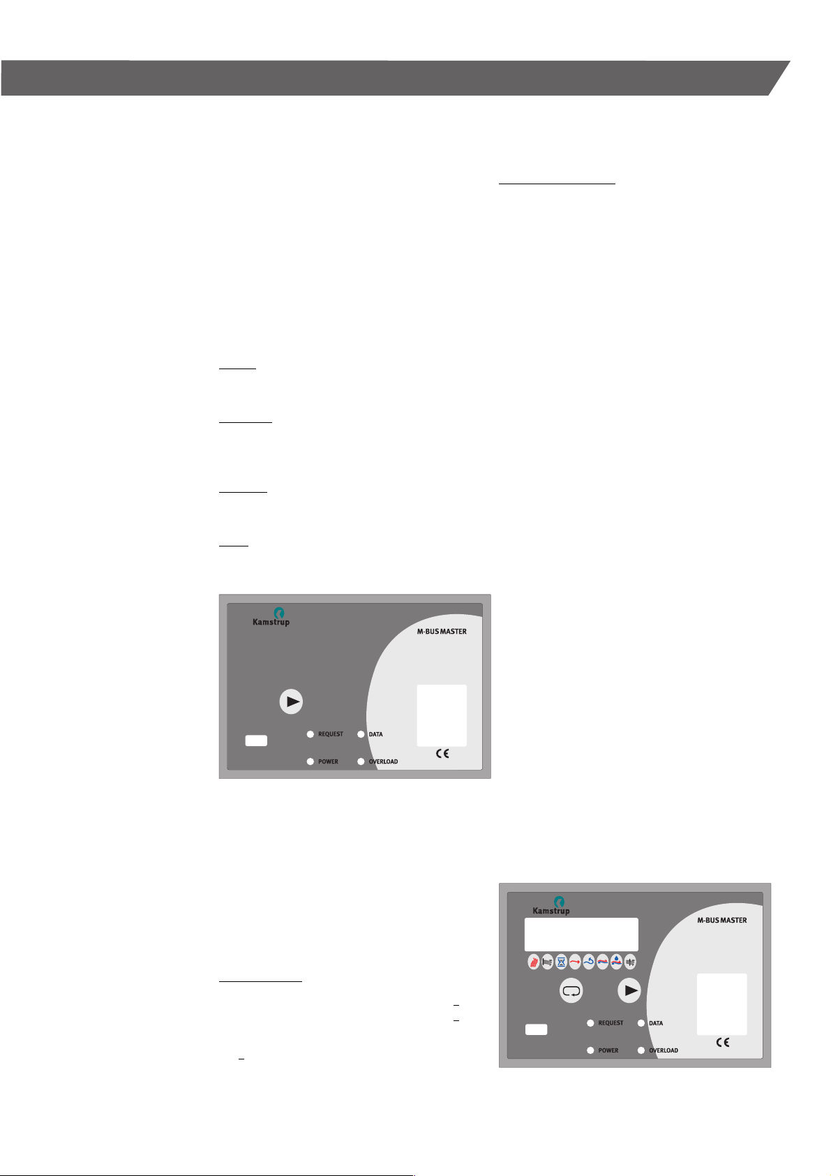
The M-Bus Master is built-up as a repeater, which
converts signals from e.g. RS232 to M-Bus format
(18-30 V/0-20 mA). The M-Bus Master has been
constructed to function together with Kamstrup’s
M-Bus Slaves and Kamstrup’s reading software.
The M-Bus Master can supply up to 40 M-Bus
Slaves at the power consumption of 1.5 mA
(1 Unit Load) per M-Bus Slave.
One or more M-Bus Cascade modules can be instal-
led, and can comprise up to 250 M-Bus Slaves.
Communication
The communication on the M-Bus consists of
vol-tage modulation from M-Bus Master to M-Bus
Slave (30 – 18 V) as well as current modulation
from M-Bus Slave to M-Bus Master (0 – 20 mA)
through an ordinary two-wire cable.
The M-Bus system has been constructed to observe
the regulations of the EN 1434-3.
The communication on the M-Bus system is asyn-
chronous serial bit transmission (EN 60870-5-1)
in half duplex mode, i.e. the communication con-
sists of 1 start bit, 8 data bits, 1 parity bit (even),
1 stop bit.
The transmission speeds are 300 baud or 2400
baud.
Addresses of M-Bus Slave units
If the M-Bus system is to function with a number
of connected M-Bus Slaves, each M-Bus Slave
must be given an identification number (address).
This is done via MULTICAL®, which contains a
unique customer number to the M-Bus Slave. The
unique address of the M-Bus Slave is equal to the
last 3–8 digits of the customer number, and the-
reby supports both primary and secondary addres-
sing. The address applies to both types of addres-
sing, and can be re-programmed either by means
of the hand-held terminal, MULTITERM, or the veri-
fication program of METERTOOL.
■
■
■
■
■
■
■
■
■
Primary addressing
The M-Bus Slave automatically reads the energy
meter’s costumer number in connection with start
or initialisation. The address must lie between 1
and 250.
If the last three digits of the customer number
exceed 250 (e.g. 345) the first digit will be ignored
and the ID number of the M-Bus Slave will only be
determined by the two last digits (e.g. 45).
If 3 systems are available each with 250 M-Bus
Slave modules, the number system is build up as
follows:
1st. system:
The energy meters are programmed with customer
numbers from 1001 to 1250.
2nd. system:
The energy meters are programmed with customer
numbers from 2001 to 2250.
3rd. system:
The energy meters are programmed with customer
numbers from 3001 to 3250.
Secondary addressing
The M-Bus Slave automatically reads the customer
number of the energy meter during start or initiali-
zation.
The M-Bus address consists of the last 3 – 8 digits
of the customer number, extending the address
possibility to 0000 0001 – 9999 9999.
Note: Kamstrup communication software,
PcM-Bus, and Kamstrup M-Bus Master
do not support secondary addressing.
The M-Bus module does not support extended
secondary address functions, e.g. enhanced secon-
dary addressing, collision detection or wild-card
search.
Each M-Bus Slave must have its own addres
The M-Bus Master always sends a message on the
bus to a given address, which is encoded in the
message (the format). Only the M-Bus Slave in que-
stion will reply.
If several M-Bus Slaves have the same address a
collision will arise, when the M-Bus Slaves reply to
the M-Bus Master.
However, there are two special addresses, which
function as follows:
Address 254:
All M-Bus Slaves will answer to this address. The
address must solely be used in systems with only
one M-Bus Slave connected, e.g. for test.
Address 255:
No M-Bus Slave will answer to this address, but
all M-Bus Slaves will receive the message. This
message makes it possible e.g. to change the baud
rate of a whole system at a time, only by sending a
format from the M-Bus Master.