Kane 425 User manual

KANE425
Flue Gas Analyser
Kane International Ltd
Kane House, Swallowfield
Welwyn Garden City
Hertfordshire, AL7 1JG
Tel: +44 (0) 1707 375550
Fax: +44 (0) 1707 393277
www.kane.co.uk
Stock No: 18366 October 2006
© Kane International Ltd

KANE425 manual Page 2
CONTENTS
Page No:
KANE425 Overview 4
ANALYSER LAYOUT & FEATURES 5-6
1. BATTERIES 7
2. BEFORE USING THE ANALYSER EVERY TIME 8-9
2.1 FRESH AIR PURGE 8
2.2 STATUS DISPLAY 8
3. USING THE ANALYSER AND ITS FOUR BUTTONS 10-12
4. USING THE ANALYSER 13-18
4.1 COMBUSTION TESTS 13
4.2 PRESSURE TEST 15
4.3 TIGHTNESS TESTING 16
4.4 DIFFERENTIAL TEMPERATURE 18
4.5 ROOM CO TESTING 19
4.6 KANE425 PRINTOUTS 20
5. USING THE MENU 21-22
6. USING THE KANE425 AS A THERMOMETER OR 23
PRESSURE METER
7. MEASURING FLUE GASES 24
8. ANALYSER PROBLEM SOLVING 25-26
9. ANALYSER ANNUAL RECALIBRATION AND SERVICE 27
10. ANALYSER SPECIFICATION 28-29
(NOTE MAY BE SUBJECT TO CHANGE)

KANE425 manual Page 3
12. ELECTROMAGNETIC COMPATIBILITY 30
APPENDIX 1 – MAIN PARAMETERS 31-33

KANE425 manual Page 4
KANE425 Overview
The KANE425 Combustion Analyser measures O
2,
CO, differential temperature
and differential pressure.
It calculates CO
2
, CO/CO
2
ratio, losses, combustion efficiency (Nett, Gross or
Condensing) & excess air.
The KANE425 Combustion Analyser can measure carbon monoxide levels in
ambient air - useful when a CO Alarm is triggered. It can also perform a 15
minute duration Room CO Test.
The analyser has a protective rubber sleeve with a magnet for “hands–free”
operation and is supplied with a flue probe with integral temperature sensor.
The large display shows 4 readings at a time and all data can be printed via an
optional infrared printer. The printed data can be 'live' data or ‘stored’ data.
The memory can store up to:
99 combustion tests
20 pressure tests
20 let-by/tightness tests
20 temperature tests
20 room CO tests
Two lines of 20 characters can be added to the header of printouts.
The analyser is controlled using 4 function buttons and a rotary dial.
The four buttons (from left to right) switch on and off the analyser, switch on
and off the backlight and torch light, switch on and off the pump and send data
to a printer or to the memory. The buttons with UP, DOWN and ENTER arrows
also change settings such as date, time, fuel, etc. when in MENU mode.

KANE425 manual Page 5
ANALYSER LAYOUT & FEATURES
Rotary Switch
Function buttons
x 4
“Battery Charging”
indicator
Water Trap
Particle Filter
Enter
Menu controls
Scroll u
p/
down
Socket for gas leak
detector
Torchlight and infra-red
emitter
Flue Gas Inlet
Temp and pressure
connections
Battery Compartment
(behind rubber sleeve)

KANE425 manual Page 6

KANE425 manual Page 7
1. BATTERIES
Battery Type
This analyser has been designed for use with disposable alkaline batteries or
rechargeable Nickel Metal Hydride (NiMH) batteries. No other battery types
are recommended.
WARNING
The battery charger unit must only be used when NiMH batteries are fitted.
Replacing Batteries
Turn over the analyser, remove its’ protective rubber sleeve and fit 4 “AA”
batteries in the battery compartment. Take great care to ensure they are fitted
with the correct battery polarity. Replace the battery cover and protective
rubber sleeve.
Switch the analyser on and select “Status” to check that the analyser’s time and
date are correct. To reset see USING THE MENU, Section 5.
Charging NiMH Batteries
Ensure that you use the correct charger. The part number is KMCU250/UK.
To fully charge NiMH batteries:
The KANE425 must be switched on.
The charger must then be connected and switched on.
When charging the red Battery Charging Indicator will illuminate.
When the KANE425 is switched off the display will show “BATTERY
CHARGING”
The first charge should be for 12 hours continuously. NiMH batteries are
suitable for top up charging at any time, even for shorts periods.
An in-vehicle charger can be used to top up the analyser's batteries from a 12
volt vehicle battery. The part number is KMCU450/12
Battery Disposal
Always dispose of depleted batteries using approved disposal methods that
protect the environment

KANE425 manual Page 8
2. BEFORE USING THE ANALYSER EVERY TIME:
Check the water trap is empty and the particle filter is not dirty:
- To empty water trap, carefully pull out the rubber drain plug and re-plug
once it is empty.
- To change the particle filter, remove the analyser’s protective rubber
sleeve, slide the water trap unit from the analyser, remove the particle
filter from its’ spigot and replace. Reconnect the water trap unit and
rubber protective sleeve.
Connect the flue probe hose to the analyser’s flue gas inlet and connect the flue
probe’s temperature plug to the T1 socket – check the plug’s orientation is
correct - see Page 6.
2.1 FRESH AIR PURGE
Position the flue probe in fresh air, then press . The analyser’s pump
starts and the analyser auto-calibrates for approximately 30 seconds. When
complete:
Select “Ratio” on the dial. In fresh air the CO reading should be 0 ppm.
Select “O
2
/Eff” on the dial. In fresh air the O
2
reading should be 20.9% +0.1%
2.2 STATUS DISPLAY
Select “Status” on the dial to view the following:
BAT 39
→Replace alkaline batteries if less than 10%
Recharge NiMH batteries if less than 20%
14:56:29 →Current time. Can be re-set via the “Menu”.
11/03/06 →Current date. Can be re-set via the “Menu”.
CAL 283
→Shows number of days until next calibration
is due.

KANE425 manual Page 9
SAFETY WARNING
This analyser extracts combustion gases that may be toxic in relatively low
concentrations. These gases are exhausted from the back of the instrument. This
analyser must only be used in well-ventilated locations by trained and
competent persons after due consideration of all the potential hazards.

KANE425 manual Page 10
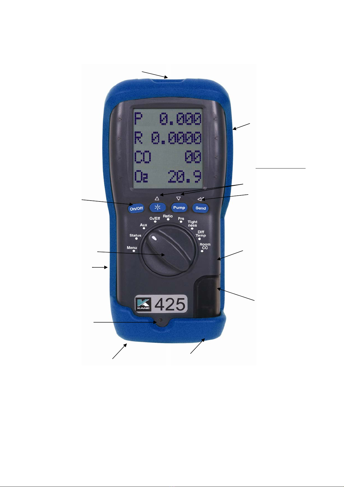
3. USING THE FOUR FUNCTION BUTTONS:
Switching
ON the
Analyser
Press button to switch the unit ON . This must be done
in fresh air to ensure that the analyser auto calibrates its’
sensors properly.
When switched on, the analyser beeps twice and briefly
displays battery %, fuel and pressure units. Its’ bottom line
counts down from 60 until the sensors are ready to use – This
normally takes 20 - 30 seconds but may take longer as sensors
get older. If the analyser will not auto calibrate, its’ sensors
need to be replaced or recalibrated by an authorised repair
centre.
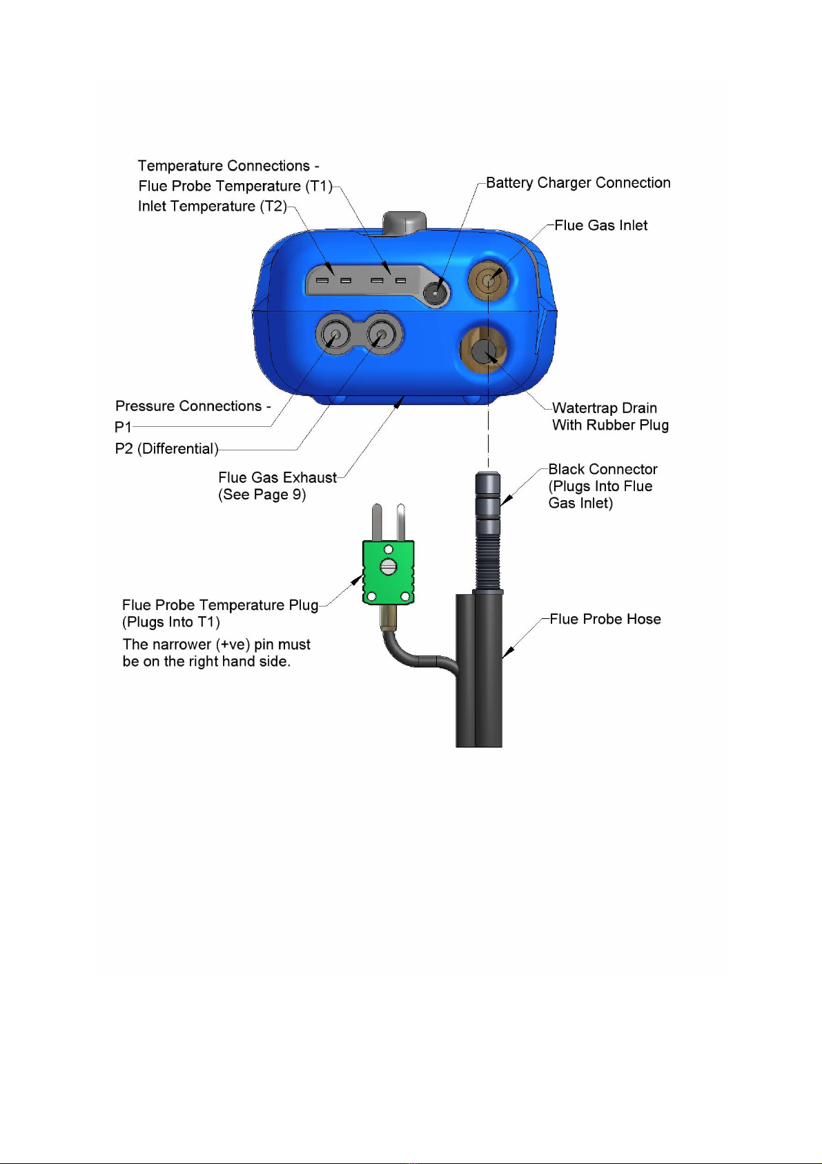
If an inlet temperature probe (optional) is connected into the T2
socket during its’ countdown, the measured temperature from
the inlet probe will be used as the inlet temperature.
If an inlet temperature probe is not connected to the analyser
during countdown the measured temperature from the flue
probe will be used as the inlet temperature.
If neither probe is connected during countdown the analyser’s
internal ambient temperature will be used as the inlet
temperature.
Switching
OFF the
Analyser
Press button to switch the analyser OFF. The display
counts down from 30 with the pump on to clean the sensors
with fresh air – If the probe is still connected, make sure
analyser and probe are in fresh air.
Press if you want to stop the countdown and return to
making measurements.
Note: The analyser will not switch off unless the CO
reading is below 20ppm

KANE425 manual Page 11
Backlight &
Torchlight
Press to switch the display's backlight and torchlight on
and off.
NOTE: Use of the backlight/torchlight increases the
current drain on the batteries
Switching
PUMP on /
off
The analyser normally operates with the pump on. Press
to switch the pump off and on.
When the pump is switched off “---PO--" is displayed instead
of the O
2
, CO & Ratio readings. The analyser also displays
"PUMP OFF" on the top line approx every 40 seconds.
NOTES:
1) The pump will not switch off if the CO reading is above
20ppm . This helps to protect the CO sensor from damage.
2) The pump will automatically switch itself off when the
rotary switch is set to Menu, Status, Pressure, Tightness or
Differential Temperature.
Zeroing the
pressure
sensor
Press and hold until the top line display shows
CAL ZERO.
Printing Data
Press and quickly release to start the analyser printing.
The analyser displays a series of bars until this is completed.
Press and release the key again to abort printing.
Make sure the printer is switched on, ready to accept data and
its’ infrared receiver is in line with the analyser’s emitter (on
top of the analyser).

KANE425 manual Page 12
Storing a set
of readings
Press and hold for approx. 2+ seconds.
The top line briefly display the log number.
Note: This STORE function is inhibited in normal
operation if the pump is switched off.
Using /
/
Buttons
The function buttons below the symbols / /are
used to navigate through the menu when the rotary switch is set
to MENU – See USING THE MENU, Section 5

KANE425 manual Page 13
4. USING THE ANALYSER:
4.1 COMBUSTION TESTS:
Insert the tip of the flue probe into the centre of the flue. The readings will
stabilise within 60 seconds assuming the boiler conditions are stable (see
Measuring Flue Gases – Section 7).
The rotary switch can be used to display the following information:
RATIO Display
NAT GAS →Can be changed via “Menu”.
R 0.0008 →CO/CO
2
ratio
CO 52
→Carbon Monoxide (ppm)
CO26.3
→Carbon Dioxide (%)
Press to print a full combustion test (also sends to PC if Bluetooth fitted).
Hold for 2+ seconds to log a full combustion report.
O2/EFF display
O29.8
→Oxygen (%) left after combustion. Should
be 20.9% +0.1% in fresh air.
TF 145.1
→Flue temperature (
o
C)
TI 5.4
→Inlet temperature (
o
C). Normally set by
flue probe during fresh air purge.
Ef C 91.3
→Defaults to Condensing boiler efficiency
(EfC). Can be changed via “Menu”.
Press to print a full combustion test (also sends to PC if Bluetooth fitted).

KANE425 manual Page 14
Hold for 2+ seconds to log a full combustion report.
AUX display
O220.9
→
CO 00
15:04:11
BAT 39
The default AUX (auxillary) display is
shown including Oxygen, Carbon
Monoxide, current time & battery status.
The AUX display can be customised via
MENU / SCREEN / AUX to change the
parameters on lines 1, 2, 3 and 4.
They remain the AUX parameters until
changed again by the user
Press to print a full combustion test (also sends to PC if Bluetooth fitted).
Hold for 2+ seconds to log a full combustion report.
Viewing / printing a logged combustion test
Select MENU / REPORT / COMB’N / VIEW
Hold or for 2+ seconds to select the log number to be viewed.
Use and to scroll through the individual readings on line 2 & 3.
Press to print the test (also sends to PC if Bluetooth fitted).
NOTE: The “AUX” display can be used to time and manually record
ambient CO levels to comply with BS7967 (see “ROOM CO” –
Section 4.5).

KANE425 manual Page 15
4.2 PRESSURE TEST
Select “Prs”. The pump stops automatically. Press to auto-zero the
pressure sensor. Using the black connectors and manometer hose, connect to P1
for single pressure or P1 and P2 for differential pressure.
PRS display
PRESSURE →Defaults to smoothing off on start-up. Can
be changed via “Menu”.
P 0.01
→Defaults to low resolution on start-up. Can
be changed via “Menu”.
mBar →Pressure units can be changed via “Menu”.
14:56:29 →Displays time to enable manually timed
tests
Press to print a pressure test (also sends to PC if Bluetooth fitted).
Hold for 2+ seconds to log a pressure report.
Viewing / printing a logged pressure test
Select MENU / REPORT / PRESSURE / VIEW
Use or to select the log number to be viewed / printed.
Press to print the test (also sends to PC if Bluetooth fitted).
SAFETY WARNING
Before using the KANE425 to measure the pressure of a gas/air ratio valve, read
the boiler manufacturer’s instructions thoroughly. If in doubt contact the boiler
manufacturer.
After adjusting a gas/air ratio valve it is essential to confirm that the CO,
CO2 and CO/CO2 ratio readings are within the boiler manufacturer’s
specified limits.

KANE425 manual Page 16
4.3 LET-BY & TIGHTNESS TESTING
Select “Tightness”. The pump stops automatically. Press to auto-zero
the pressure sensor. Connect from the test point to P1 using a black connector
and manometer hose.
The display shows “LET BY?”. Use , and to select YES or NO.
If YES is selected set the let-by pressure then press to start the let-by test.
The display shows:
LET BY →The let-by test is automatically stored in
the memory
P1 10.15
→Pressure at start of let-by test
P2 10.15
→Real time pressure reading
TIME 59
→Let-by default time is 1 minute. Can be
changed via “Menu”
If the let-by test fails simply move the rotary switch to any position other than
“tightness” to abort the test.
If the let-by test passes adjust the gas pressure for the tightness test and press
to start the stabilisation test. The display shows:
STABIL’N
P1 20.01
→Real time pressure during the stabilisation
test
mBAR →Pressure units
TIME 59
→Stabilisation default time is 1 minute. Can
be changed via “Menu”.

KANE425 manual Page 17
When stabilisation is complete press to start the tightness test:
TIGHTN’S
P1 20.01
→Pressure at start of tightness test
P1 20.01
→Real time pressure reading
TIME 119
→Tightness default time is 2 minutes. Can
be changed via “Menu”.
When complete the display will show:
LOG 01
→The tightness test is automatically stored in the
memory. The log number for the test is displayed.
P1 20.01
→Pressure at start of tightness test
P2 19.98
→Pressure at end of tightness test
PRINT
Ð
Press to print the tightness test (also sends to PC if Bluetooth fitted).
Viewing / printing a logged tightness test
Select MENU / REPORT / TIGHTN’S / VIEW
Use or to select the log number to be viewed / printed.
Press to print the test (also sends to PC if Bluetooth fitted).

KANE425 manual Page 18
4.4 DIFFERENTIAL TEMPERATURE
Select “Diff Temp” to measure flow, return and differential temperatures
DIFF TEMP display
TEMP →Pump stops automatically when dial is
moved to Diff Temp
T1 60.4
→Use the T1 connection for the flow
temperature sensor
T2 55.2
→Use the T2 connection for the return
temperature sensor
∆T 5.2
→Real time temperature difference
Press to print a differential temperature test (also sends to PC if Bluetooth
fitted).
Hold for 2+ seconds to log a differential temperature report.
Viewing / printing a differential temperature test
Select MENU / REPORT / TEMP / VIEW
Use or to select the log number to be printed.
Press to print the test (also sends to PC if Bluetooth fitted).

KANE425 manual Page 19
4.5 ROOM CO TESTING
Select “Room CO” for CO investigations.
Press to start the 15 minute duration room CO test.
ROOM CO display
ROOM
CO
→When complete the room CO test is
automatically stored in the memory
CO 00
→Real time CO reading (ppm)
TEST 00
→Test 00 = initial reading
Test 15 = final reading
LOG 01
→
The log number for the test is displayed.
Press to print the room CO test (also sends to PC if Bluetooth fitted)
Viewing / printing a logged Room CO test
Select MENU / REPORT / ROOM CO / VIEW
Use or to select the log number to be viewed / printed.
Use to view individual readings.
Hold for 2+ seconds to print the test (also sends to PC if Bluetooth
fitted).
NOTE: To abort a room CO test move the rotary switch to any position
other than “Room CO”.
NOTE: The “AUX” display can be used to time and manually record ambient
CO levels to comply with BS7967 – see Page 14.

KANE425 manual Page 20
4.6 KANE425 PRINTOUTS
Table of contents
Other Kane Analytical Instrument manuals
Popular Analytical Instrument manuals by other brands

Vivax Metrotech
Vivax Metrotech vCamDrain user manual

LaserLiner
LaserLiner DistanceMaster Pocket Pro manual

kaarta
kaarta STENCIL 2 user guide

Maxtec
Maxtec UltraMax O2 Instructions for use

Air Monitor Corporation
Air Monitor Corporation VOLU-probe/1 INSTALLATION PROCEDURE

Omron
Omron FZ-SLC15 instruction sheet