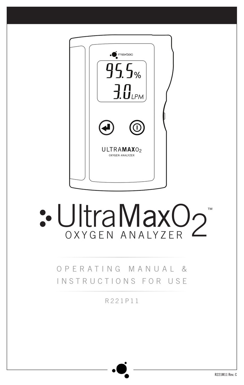
Maxtec UltraMax O2 User manual

LPM
ULTRAMAX0
2
OXYGEN ANALYZER
UltraMax O2
OXYGEN ANALYZER
Instructions for Use
ENGLISH
R221M11 Rev. M

ENGLISH 2WWW.MAXTEC.COM • (800) 748-5355
NOTE: The UltraMaxO2 is for use only by trained personnel. Before use, all individuals using
the UltraMaxO2 should become familiar with the information contained in this Operation
Manual. Adherence to these instructions is necessary for safe, effective product performance.
Thoroughly read all instructions and labeling provided with this device and any other equip-
ment that will be used.
CLASSIFICATION
Protection against electric shock.................................................... Internally powered equipment
Protection against water................................................................................................................IPX1
Mode of operation..............................................................................................................Continuous
Sterilization.................................................................................................................. See section 6.0
Flammable anaesthetic mixture....Not for use in presence of flammable anaesthetic mixtures
Power specification..............................................................................1.8-3.2V 32mW10mA
CAUTION: Federal law restricts this device to sale by or on the order of a physician or other
licensed healthcare practitioner.
Product Disposal Instructions:
The sensor, batteries, and circuit board are not suitable for regular trash disposal.
Return sensor to Maxtec for proper disposal or dispose according to local guide-
lines. Follow local guidelines for disposal of other components.
INDICATIONS FOR USE
The UltraMaxO2 Oxygen Analyzer is a tool used to measure oxygen purity, flow and pressure
at the outlet of an oxygen concentrator. It is not intended to be used by patients who are
prescribed oxygen, nor is it intended to continuously monitor or confirm oxygen delivery to
a patient. The UltraMaxO2 Oxygen Analyzer is intended to be used in an environment where
oxygen concentrators are being serviced or repaired. This includes Hospitals, Nursing Homes,
Extended Care Facilities, Patient Homes, and Respiratory Device Service and Repair Centers.
WARRANTY
Under normal operating conditions, Maxtec warrants the UltraMaxO2 to be free from defects
of workmanship or materials for a period of Three (3) years from the date of shipment from
Maxtec, provided that the unit is properly operated and maintained in accordance with Maxtec’s
operating instructions. Based on Maxtec product evaluation, Maxtec’s sole obligation under
the foregoing warranty is limited to making replacements, repairs, or issuing credit for equip-
ment found to be defective. This warranty extends only to the buyer purchasing the equipment
directly from Maxtec or through Maxtec’s designated distributors and agents as new equipment.
Routine maintenance items, such as batteries, are excluded from warranty. Maxtec and any
other subsidiaries shall not be liable to the purchaser or other persons for incidental or con-
sequential damages or equipment that has been subject to abuse, misuse, mis-application,
alteration, negligence or accident.
These warranties are exclusive and in lieu of all other warranties, expressed or implied, includ-
ing warranty of merchantability and fitness for a particular purpose.
PRINCIPLE OF OPERATION
The UltraMaxO2 Oxygen Analyzer measures oxygen concentration and flow using ultrasound
technology and measures pressure using a piezoresistive silicon pressure sensor.
WARNINGS
Indicates a potentially hazardous situation, if not avoided, could result in death or serious injury.
◆ Not for use in an MRI environment.
◆ Improper use of the UltraMaxO2 can cause inaccurate oxygen readings leading to improper
treatment and/or patient harm. Follow the procedures outlined in this user manual.
◆ The UltraMaxO2 is for checking oxygen concentrators only.
DO NOT use the UltraMaxO2 for continuous oxygen monitoring.
DO NOT use the UltraMaxO2 to measure the oxygen concentration of a concentrator when
flowing at rates lower than its optimal performance as specified by the concentrator
manufacturer; generally 4 LPM or less on concentrators that have a maximum flow of 10
LPM, and 1 LPM or less on concentrators that have a maximum flow of 5 LPM.
◆ Not for use in anesthesia applications or for measuring oxygen concentration from any
sources other than conventional oxygen concentrators.
◆ Not for use with inhalation agents. Operating the UltraMaxO2 in flammable or explosive
environments may result in fire or explosion.
◆ Not suitable for use in the presence of flammable anesthetic mixtures.
◆ Oxygen rapidly accelerates combustion.
DO NOT smoke while using the UltraMaxO2 for checking oxygen concentrators.
Users must become thoroughly familiar with the information contained in this Operation
Manual before use. Strict adherence to the operating instructions is necessary for safe, effec-
tive product performance. This product will perform only as designed if operated in accor-
dance with the manufacturer’s operating instructions.
◆ Use only genuine Maxtec accessories. Failure to do so may seriously impair the performance
of the UltraMaxO2. Repair or alteration of the UltraMaxO2 by anyone other than an autho-
rized Maxtec service representative could cause the product to fail to perform as designed.
◆ Use of the UltraMaxO2 near devices that generate electrical fields may cause erratic readings.
◆ If the UltraMaxO2 is ever exposed to liquids from spills or immersion, immediately remove
the batteries and let the device dry completely. When dry, replace the batteries and check
for proper operation.
DO NOT autoclave or expose the UltraMaxO2 to high temperatures (>60°C).
DO NOT use ethylene oxide sterilization.
DO NOT expose the UltraMaxO2 to irradiation, vacuum, steam, or harsh chemicals.
DO NOT expose the UltraMaxO2 to pressure greater than 50 psi. Exposure to pressure
above 50 psi could cause leaks in the device which may adversely affect performance in
flow and pressure readings.
CAUTIONS
Indicates a potentially hazardous situation, if not avoided, could result in minor or moderate
injury and property damage.
◆ Replace the batteries with high quality AA Alkaline or Lithium batteries.
DO NOT use rechargeable batteries.
◆ When not in use for periods greater than 30 days remove the batteries to protect the
UltraMaxO2 from potential battery leakage.
◆ Avoid dropping the UltraMaxO2 to prevent damage which may adversely affect its perfor-
mance. If damage to the device is suspected, perform the calibration verification procedure
in Section 2.3 of this operating manual.
◆ Avoid foreign matter entry into the UltraMaxO2.
DO NOT use the UltraMaxO2 to check a concentrator with a humidifier in place. Humidity
from a humidifier could damage the device.
DO NOT check a concentrator while holding the mode button or the reading will be
inaccurate.
◆ Following storage in extremely hot or cold conditions, allow the gas to flow through the
analyzer long enough for the internal sensors to reach the gas stream temperature, or wait
for the analyzer to equilibrate to room temperature before use.
Conforms to:
AAMI STD ES60601-1, ISO STD
80601-2-55, IEC STDS 60601-
1-6, 60601-1-8 & 62366
Certified to:
CSA STD C22.2 No. 60601-1
Maxtec
2305 South 1070 West
Salt Lake City, Utah 84119
USA
phone: (800) 748.5355
fax: (801) 973.6090
email: sales@maxtec.com
web: www.maxtec.com
NOTE: The latest edition of this operating manual can be downloaded from our website at www.maxtec.com
EN Instructions for Use
WWW.MAXTEC.COM • (800) 748-5355 3ENGLISH
Symbol Guide
The following symbols and safety labels are found on the UltraMaxO2:
Warning
Authorized
Representative in the
European Commuity
Low Battery Serial Number
Do not throw away.
Follow local guidelines
for disposal
Catalog Number
Meets ETL standards Liter per minute flow
Manufacturer Pounds per
square inch
Date of Manufacture Kilopascals
Medical Device Percent
Ingress Protection Rating Gas sample inlet
Federal law (USA) restricts
this device to sale by or
on order of a physician.
Gas sample outlet
Latex free Direct current
On/O Button DO NOT
Mode Button Caution
Follow instructions for use
1.0 SYSTEM OVERVIEW
1.1 Description & Principle of Operation
The UltraMaxO2 is an oxygen analyzer designed to check the oxygen concentration, flow and
outlet pressure of oxygen concentrators. The UltraMaxO2 provides unparalleled performance
and reliability from its advanced design that includes the following features and operational
benefits:
•Accurate oxygen measurements.
•No in-field calibration required.
•Convenient ability to measure pressure in PSI or kPa.
•Durable, compact design.
•Large, easy-to-read, liquid crystal display (LCD).
•Shielded, reinforced sample gas inlet port.
•Long battery life with 2 AA batteries.
•Auto-off after 4 minutes.
•Low battery indication.
•Self-diagnostics.
•Easy to clean.
1.2 Indication for Use
The UltraMaxO2 Oxygen Analyzer is a tool used to measure oxygen purity, flow and pressure
of an oxygen concentrator. The UltraMaxO2 Oxygen Analyzer is intended to be used in an envi-
ronment where oxygen concentrators are being serviced or repaired. This includes Hospitals,
Nursing Homes, Extended Care Facilities, Patient Homes, and Respiratory Device Service and
Repair Centers.
1.3 Component Identification
1
6
7
8
9
q
w
45
2
3
1
3 1/2 DIGIT DISPLAY — The LCD provides direct readout of oxygen concentration, gas
flow and gas pressure. The LCD also displays error codes as necessary.
2
MODE BUTTON — Switches between measuring the concentration of gas produced by an
oxygen concentrator and pure oxygen (for calibration verification).
3
ON/OFF BUTTON — Turns the device on or off.
4
PSI — Indicates the pressure measurement is in units of pounds per square inch.
5
KPA — Indicates the pressure measurement is in units of kilopascals.
6
GAS SAMPLE INLET — Used to receive the gas sample.
7
% SYMBOL — Illuminated next to the concentration measurement.
8
LOW BATTERY INDICATOR — Indicates the voltage of the batteries is below normal oper-
ating levels.
9
LPM — Illuminated next to the flow measurement. (Not shown when in calibration veri-
fication mode).
q
GAS SAMPLE OUTLET — Used as an outlet for the gas sample and as a trigger for pressure
measurement when occluded.
w
BATTERY DOOR
GAS SAMPLE TUBING — Used to connect to gas sample sources (not shown).

ENGLISH 4WWW.MAXTEC.COM • (800) 748-5355
2.0 OPERATING INSTRUCTIONS
2.1 Oxygen, Flow and Pressure Measurement
To check oxygen concentration, flow and pressure of a gas sample from a concentrator:
Connect the gas sample tubing to the gas sample inlet of the UltraMaxO2.
1. Attach the other end of the gas sample tubing to the oxygen concentrator.
2. Initiate the flow of gas to the UltraMaxO2 at a rate of 1-10 liters per minute (2 liters
per minute is recommended). Ensure the concentrator’s output is stable per the
concentrator manufacturer’s recommendations.
3. Turn on the UltraMaxO2.
4. Allow the oxygen reading to stabilize for approximately 10 seconds before reading the
oxygen concentration and flow.
5. To check pressure, cover the gas sample outlet with thumb or finger while gas is
flowing.
6. Wait 5 seconds for the display to read pressure.
DO NOT hold the mode button while checking a concentrator or the reading will be
inaccurate.
2.2 Switching Pressure Units of Measure
The UltraMaxO2 can measure pressure in PSI or kPa. The UltraMaxO2 is factory set to measure
in PSI. To switch to kPa:
1. Using a #1 Phillips screwdriver loosen the battery door screw and remove the battery
door.
2. Toggle the switch inside the battery compartment.
3. Replace the battery door and tighten the battery door screw.
2.3 Calibration Verification Procedure
A calibration verification mode is provided to verify that the UltraMaxO2 is functioning prop-
erly. To perform the calibration verification:
1. Turn on the UltraMaxO2.
2. Connect a source of pure oxygen (≥99.95%) to the gas sample inlet.
3. Flow 2-5 LPM of gas into the UltraMaxO2. Ensure that the gas flowing to the
UltraMaxO2 is at a stable temperature.
4. Press and hold the mode button. While holding the mode button, the gas
measurement should read between 98.5 and 101.5% oxygen. If the gas measurement
is not within this range, call Maxtec Customer Service. Calibration verification mode is
indicated by “CAL” and “VER” flashing on screen beneath the gas measurement.
3.0 FACTORS INFLUENCING
ACCURATE READINGS
3.1 Effects of Temperature
The UltraMaxO2 compensates for temperature and will perform within specifications through-
out the operating temperature range. However, taking measurements during rapid changes in
gas temperature should be avoided.
3.2 Effects of Humidity
The UltraMaxO2 has a humidity sensor to detect and compensate for the humidity of gas
entering the device. However, high levels (condensing) of humidity can affect the accuracy
and reliability of the UltraMaxO2. To prevent possible damage:
Avoid usage in environments of greater than 95% relative humidity.
DO NOT use this device in a breathing circuit.
DO NOT breathe or blow into the UltraMaxO2.
3.3 Effects of Other Gases
The UltraMaxO2 is designed to measure two different types of gas mixtures:
•Oxygen, nitrogen and argon from oxygen concentrators.
•Pure oxygen during calibration verification mode.
Any other concentrations or combinations of gases will cause the UltraMaxO2 to measure
oxygen concentration incorrectly.
3.4 Effects of Low Flow
Oxygen concentrators function on the principle of removing nitrogen gas from air, leaving
concentrated oxygen and argon at a specific oxygen to argon ratio. This operating principle
may be altered when concentrators are set to flow at the low end of their operational range. At
low flows they may output a low oxygen concentration, e.g. 85% to 91%, for reasons other than
high nitrogen, possibly due to an increase in argon content. The UltraMaxO2 requires that the
ratio of oxygen to argon remain constant in order to guarantee an accuracy of +/-1.5% oxygen.
DO NOT use the UltraMaxO2 to measure the oxygen concentration of a concentrator when
flowing at rates lower than its optimal performance as specified by the concentrator
manufacturer; generally 4 LPM or less on concentrators that have a maximum flow of 10
LPM, and 1 LPM or less on concentrators that have a maximum flow of 5 LPM.
4.0 ERROR CODES
The UltraMaxO2 has self diagnostic features built into the software to detect faulty readings
outside of normal operating ranges. The codes, descriptions and recommended actions are:
E01: Oxygen measurement out of range Hi (≥102.0% calculated by algorithm). Recommended
Action: Verify that the UltraMax O2 is being used in the correct mode (Concentrator or
Calibration Verification mode). If error code repeats; perform a calibration verification per sec-
tion 2.3 of this manual. If error code repeats again; contact Maxtec Customer Service.
E02: Oxygen measurement out of range Low (≤-2.0% calculated by algorithm). Recommended
Action: Verify that the UltraMax O2 is being used in the correct mode (Concentrator or
Calibration Verification mode). If error code repeats; perform a calibration verification per sec-
tion 2.3 of this manual. If error code repeats again; contact Maxtec Customer Service.
E03: Device memory corrupt or missing. Recommended Action: Return the UltraMaxO2 to the
manufacturer for factory repair.
E04: Signal reading not stable. Recommended Action: Return the UltraMaxO2 to the manu-
facturer for factory repair.
E05: Pressure measurement out of Range Hi (≥50 PSI). Recommended Action: Check the pres-
sure on a known gas source pressure. If error code repeats; contact Maxtec Customer Service.
E06: Outside of operating temperature Hi (≥40° C). Recommended action: The UltraMaxO2 is
too hot, cool the device closer to room temperature before use.
E07: Outside of operating temperature Low (≤15° C). Recommended action: The UltraMaxO2 is
too cold, warm the device closer to room temperature before use.
E08: Device self check found error. Recommended Action: Remove and replace the batteries. If
error code repeats; return the UltraMaxO2 to the manufacturer for factory repair.
5.0 CHANGING THE BATTERIES
Batteries should be changed by service personnel. Use only brand name batteries. Replace
with two AA batteries and insert per orientation marked on the device. Batteries should be
changed when the icon illuminates. The icon will remain lit until the batteries are
changed. If the battery power level is too low the UltraMaxO2 will not power on until the
batteries are changed.
5.1 Battery Replacement Procedure
1. Using a #1 Phillips screwdriver loosen the battery door screw and remove the battery
door.
2. Remove the batteries.
3. Insert new batteries ensuring correct polarity. DO NOT use rechargeable batteries.
4. Replace the battery door and tighten the battery door screw.
5. If the UltraMaxO2 does not power on when done verify the batteries are installed
correctly and that the batteries are fresh.

WWW.MAXTEC.COM • (800) 748-5355 5ENGLISH
6.0 CLEANING AND MAINTENANCE
Use caution to prevent any fluid from entering the UltraMaxO2.
DO NOT soak or immerse the UltraMaxO2 in fluid.
DO NOT autoclave or expose the UltraMaxO2 to ethylene oxide sterilization.
6.1 Cleaning
Wipe down the exterior surfaces of the UltraMaxO2 with a moist cloth and mild hand or dish
soap (pH 6-8).
6.2 Maintenance
Replace the batteries with high quality AA Alkaline or Lithium batteries.
DO NOT use rechargeable batteries.
•When not in use for periods greater than 30 days, remove the batteries to protect the
UltraMaxO2 from potential battery leakage.
•Store the UltraMaxO2 between -15˚C and 60˚C (5˚F - 140˚F)
7.0 SPECIFICATIONS
Oxygen
Oxygen Measurement Range
(from a concentrator).........................................................................................................20.9 - 96%
Oxygen Measurement Accuracy.......................................................................±1.5 % of full scale at
constant temperature and optimal flow*
Oxygen Measurement Resolution..................................................................................0.1% Oxygen
Flow
Flow Measurement Range...................................................................................................0 - 10 LPM
Flow Measurement Accuracy................................................................................................±0.2 LPM
Flow Measurement Resolution................................................................................................0.1 LPM
Pressure
Pressure Measurement Range............................................................0.5 - 50 (PSI), 3.4 - 344 (kPa)
Pressure Measurement Accuracy ..............................................................±0.5% (PSI), ±0.5% (kPa)
Pressure Measurement Resolution .......................0.1 (PSI), 0.1 up to 199, 1 from 200 to 344 (kPa)
Response Time .................................................................................................................≤17 seconds
Warm-up Time.....................................................................................................................< 1 second
Operating Temperature..............................................................................15˚C - 40˚C (59˚F-104˚F)
Storage Temperature..................................................................................-15˚C - 60˚C (5˚F-140˚F)
Pressure....................................................................................................................800 - 1000 mBars
Humidity ...................................................................................................0 - 95% (non-condensing)
Power Requirements..............................................................2 AA Alkaline batteries (2 x 1.5 Volts)
Battery Life...................................................................................≥1,100 hours (16,500 read cycles)
Low Battery Indication ..........................................................."Low Battery" icon displayed on LCD
Dimensions ....................................................3.16” x 5.10” x 1.04” (80.3mm x 129.5mm x 26.4mm)
Weight.............................................................................................................................0.4 lbs (181 g)
8.0 SPARE PARTS AND ACCESSORIES
8.1 Included with Your Unit
PART NUMBER ITEM
R211M11 Operating Manual and Instructions for Use*
RP46P05 Gas Sample Tubing
8.2 Optional Accessories
PART NUMBER ITEM
R221P15 Soft Cover
Repair of this equipment must be performed by a qualified service technician experienced in
repair of portable hand held medical equipment.
Equipment in need of repair shall be sent to:
Maxtec
Customer Service Department
2305 South 1070 West
Salt Lake City, UT 84119
(Include RMA number issued by Customer Service)
9.0 ELECTROMAGNETIC
COMPATIBILITY
The information contained in this section (such as separation distances) is in general spe-
cifically written with regard to the UltraMaxO2. The numbers provided will not guarantee
faultless operation but should provide reasonable assurance of such. This information may
not be applicable to other medical electrical equipment; older equipment may be particularly
susceptible to interference.
Note: Medical electrical equipment requires special precautions regarding electromagnetic
compatibility (EMC) and needs to be installed and put into service according to the EMC infor-
mation provided in this document and the remainder of the instructions for use this device.
Portable and mobile RF communications equipment can affect medical electrical equipment.
Cables and accessories not specified within the instructions for use are not authorized. Using
other cables and/or accessories may adversely impact safety, performance and electromag-
netic compatibility (increased emission and decreased immunity).
Care should be taken if the equipment is used adjacent to or stacked with other equipment;
if adjacent or stacked use is inevitable, the equipment should be observed to verify normal
operation in the configuration in which it will be used.
ELECTROMAGNETIC EMISSIONS
This equipment is intended for use in the electromagnetic environment specified below.
The user of this equipment should assure that it is used in such an environment.
EMISSIONS COMPLIANCE
ACCORDING TO ELECTROMAGNETIC ENVIRONMENT
RF Emissions
(CISPR 11)
Group 1 The UltraMaxO2 uses RF energy only for its
internal function. Therefore, its RF emissions
are very low and are not likely to cause any
interference in nearby electronic equipment.
CISPR Emissions
Classification
Class A The UltraMaxO2 is suitable for use in all
establishments other than domestic and
those directly connected to the public low-
voltage power supply network that supplies
buildings used for domestic purposes.
NOTE: The EMISSIONS characteristics of this
equipment make it suitable for use in industrial
areas and hospitals (CISPR 11 class A). If it is used
in a residential environment (for which CISPR
11 class B is normally required) this equipment
might not oer adequate protection to radio-
frequency communication services. The user
might need to take mitigation measures, such
as relocating or re-orienting the equipment.
Harmonic Emissions
(IEC 61000-3-2)
Class A
Voltage Fluctuations Complies

ENGLISH 6WWW.MAXTEC.COM • (800) 748-5355
ELECTROMAGNETIC IMMUNITY
This equipment is intended for use in the electromagnetic environment specified below.
The user of this equipment should assure that it is used in such an environment.
IMMUNITY AGAINST IEC 60601-1-2: (4TH
EDITION) TEST LEVEL
ELECTROMAGNETIC
ENVIRONMENT
Professional
Healthcare Facility
Environment
Home
Healthcare
Environment
Electrostatic
discharge, ESD
(IEC 61000-4-2)
Contact discharge: ±8 kV
Air discharge: ±2 kV, ±4 kV, ±8 kV, ±15 kV
Floors should be wood,
concrete, or ceramic
tile. If floors are covered
with synthetic material,
the relative humidity
should be kept at levels
to reduce electrostatic
charge to suitable levels.
Mains power quality
should be that of a
typical commercial or
hospital environment.
Equipment which emits
high levels of power
line magnetic fields (in
excess of 30A/m) should
be kept at a distance to
reduce the likelihood of
interference.
If user requires
continued operation
during power mains
interruptions,
ensure that batteries
are installed and
charged. Ensure that
battery life exceeds
longest anticipated
power outages or
provide an additional
uninterruptible
power source.
Electrical fast
transients / bursts
(IEC 61000-4-5)
Power supply lines: ±2 kV
Longer input / output lines: ±1 kV
Surges on AC mains
lines (IEC 61000-4-5)
Common mode: ±2 kV
Diferential mode: ±1 kV
3 A/m power
frequency magnetic
field 50/60 Hz
(IEC 61000-4-8)
30 A/m
50 Hz or 60 Hz
Voltage dips and
short interruptions
on AC mains input
lines (IEC 61000-4-11)
Dip>95%, 0.5 periods
Dip 60%, 5 periods
Dip 30%, 25 periods
Dip >95%, 5 seconds
Recommended separation distances between portable and mobile
RF communications equipment and the equipment
RATED MAXIMUM
OUTPUT POWER OF
TRANSMITTER
W
Separation distance according to frequency
of transmitters in meters
150 kHz to 80 MHz
d=1.2/V1] √P
80 MHz to 800 MHz
d=1.2/V1] √P
800MHz to 2.5 GHz
d=2.3 √P
0.01 0.12 0.12 0.23
0.1 0.38 0.38 0.73
11.2 1.2 2.3
10 3.8 3.8 7.3
100 12 12 23
For transmitters rated at a maximum output power not listed above, the recommended
separation distance d in meters (m) can be estimated using the equation applicable to
the frequency of the transmitter, where P is the maximum output power rating of the
transmitter in watts (W) according to the transmitter manufacturer.
NOTE 1: At 80 MHz and 800 MHz, the separation distance
for the higher frequency range applies.
NOTE 2: These guidelines may not apply in all situations. Electromagnetic propogation
is aected by absorption and reflection from structures, objects, and people.
This equipment is intended for use in the electromagnetic environment
specified below. The customer or the user of this equipment
should assure that it is used in such an environment.
IMMUNITY
TEST
IEC 60601-1-2: 2014 (4TH
EDITION) TEST LEVEL
ELECTROMAGNETIC
ENVIRONMENT - GUIDANCE
Professional
Healthcare
Facility
Environment
Home Healthcare
Environment
Conducted
RF coupled
into lines (IEC
61000-4-6)
3V (0.15 - 80
MHz)
6V (ISM bands)
3V (0.15 - 80 MHz)
6V (ISM &
Amateur bands)
Portable and mobile RF communications
equipment (including cables) should
be used no closer to any part of the
recommended separation distance calculated
from the equation applicable to the
frequency of the transmitter as below.
Recommended sparation distance:
d=1.2 √P
d=1.2 √P 80 MHz to 800 MHz
d=2.3 √P 800 MHz to 2.7 GHz
Where P is the maximum output
power rating of the transmitter in
watts (W) according to the transmitter
manufacturer and d is the recommended
separation distance in metres (m).
Field strengths from fixed RF transmitters,
as determined by an electromagnetic site
survey a, should be less than the compliance
level in each frequency range b.
Interference may occur in the vicinity of
equipment marked with the following symbol:
Radiated RF
immunity
(IEC
61000-4-3)
3 V/m
80 MHz - 2.7 GHz
80% @ 1 KHz
AM Modulation
10 V/m
80 MHz - 2.7 GHz
80% @ 1 KHz
AM Modulation
The ISM (industrial, scientific and medical) bands between 150 kHz and 80 MHz are 6,765 MHz
to 6,795 MHz; 13,553 MHz to 13,567 MHz; 26,957 MHz to 27,283 MHz; and 40,66 MHz to 40,70 MHz.
Field strengths from fixed transmitters, such as base stations for radio (cellular/cordless) tele-
phones and land mobile radios, amateur radio, AM and FM radio broadcast and TV broadcast
cannot be predicted theoretically with accuracy. To assess the electromagnetic environment
due to fixed RF transmitters, an electromagnetic site survey should be considered. If the mea-
sured field strength in the location in which the equipment is used exceeds the applicable
RF compliance level above, the equipment should be observed to verify normal operation. If
abnormal performance is observed, additional measures may be necessary, such as reorient-
ing or relocating the equipment.

7
This page intentionally left blank

2305 South 1070 West
Salt Lake City, Utah 84119
(800) 748-5355
www.maxtec.com
Table of contents
Other Maxtec Analytical Instrument manuals

Maxtec
Maxtec MaxBlend 2+p User manual

Maxtec
Maxtec Handi+ User manual

Maxtec
Maxtec MAXO2+ A User manual

Maxtec
Maxtec MaxO2 Plus User manual

Maxtec
Maxtec UltraMaxO2 User manual

Maxtec
Maxtec MaxO2 OM-25A User manual

Maxtec
Maxtec Handi+ N2 User manual

Maxtec
Maxtec MaxO2 Plus User manual

Maxtec
Maxtec MaxN2+ User manual
Popular Analytical Instrument manuals by other brands

Calculated Industries
Calculated Industries LaserDIMENSIONMASTER 3336 user guide

LaserLiner
LaserLiner VideoScope XXL manual

ABB
ABB ZDT Installation and operating guide

Fuji Electric
Fuji Electric ZFK8 Series instruction manual

Swann
Swann AMI Trides Operator's manual

GW Instek
GW Instek LCR-816 Operating instruction