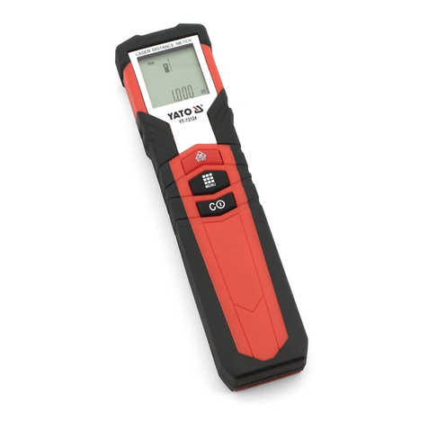
YATO YT-73126 User manual

INSTRUKCJA ORYGINALNA 1
DALMIERZ LASEROWY
LASER DISTANCE METER
LASER-ENTFERNUNGSMESSER
ЛАЗЕРНЫЙ ДАЛЬНОМЕР
ЛАЗЕРНИЙ ДАЛЕКОМІР
LAZERINIS TOLIAMATIS
LĀZERA TĀLMĒRS
LASEROVÝ DÁLKOMĚR
LASEROVÝ DIAĽKOMER
LÉZERES TÁVMÉRŐ
TELEMETRU CU LASER
TELÉMETRO DE LASER
TELEMETRE LASER
TELEMETRO LASER
LASERAFSTANDSMETER
ΤΗΛΕΜΕΤΡΟ ΛΕЇΖΕΡ
PL
GB
D
RUS
UA
LT
LV
CZ
SK
H
RO
E
F
I
NL
GR
YT-73126
YT-73127

INSTRUKCJA ORYGINALNA
2
PL GB D RUS UA LT LV CZ SK H RO E F I NL GR
TOYA S.A. ul. Sołtysowicka 13-15, 51-168 Wrocław, Polska
PL
1. wyświetlacz
2. znacznik wskaźnika laserowego
3. pokrywa komory baterii
4. wskaźnik laserowy
5. gniazdo USB
6. włącznik
7. pomiar
8. wybór trybu pomiaru
9. banki pamięci
10. dodawanie / odejmowanie
11. baza pomiarowa / jednostka
12. sygnałdźwiękowy
13. poziom baterii
14. symbol pomiaru pojedynczego
15. symbol działającego wskaźnika
laserowego
16. baza pomiarowa – czoło dalmierza
17. baza pomiarowa – gniazdo statywowe
18. baza pomiarowa – tyłdalmierza
19. wskaźnik kąta
20. symbol banku pamięci
21. wartość pomiaru 1
22. wartość pomiaru 2 / MIN
23. wartość pomiaru 3 / MAX
24. suma / ostatnia wartość pomiaru / wynik
obliczeń
GB
1. display
2. laser indicator marker
3. battery compartment cover
4. laser indicator
5. USB slot
6. switch
7. measurement
8. measuring mode selector
9. memory bank
10. adding/subtracting
11. measuring base / unit
12. acoustic signal
13. battery level
14. single measurement symbol
15. operative laser indicator symbol
16. measuring base - head of range-finder
17. measuring base - tripod slot
18. measuring base - rear of range-finder
19. angle indicator
20. memory bank symbol
21. measurement value 1
22. measurement value 2 / MIN
23. measurement value 3 / MAX
24. sum / last measurement value / result
of calculation
D
1. Display
2. Entfernungsmesser
3. Deckel Batteriefach
4. Laseranzeige
5. USB-Port
6. Steuerschalter
7. Messung
8. Messmodus wählen
9. Datenbanken
10. Addieren / Subtrahieren
11. Messungsbasis / Einheit
12. Akustisches Signal
13. Batteriekapazität
14. Anzeige Einzelmessung
15. Anzeige Laserfunktion
16. Messungsbasis – Gerätefront
17. Messungsbasis – Stativaufnahme
18. Messungsbasis – Gerätehinterteil
19. Anzeige Messwinkel
20. Anzeige Speicher
21. Messwert 1
22. Messwert 2 / MIN
23. Messwert 3 / MAX
24. Summe / Letzter Messwert / Messergebnis
I
4
7
8
11
6
5
2
1
3
9
10
12
18
17
16
15
14
13 19
20
21
22
23
24

INSTRUKCJA ORYGINALNA 3
PL GB D RUS UA LT LV CZ SK H RO E F I NL GR
UA LTRUS
1. дисплей
2. обозначение лазерной указки
3. крышка отсека батареи
4. лазерная указка
5. разъем USB
6. включатель
7. измерение
8. выбор режима измерения
9. ячейки памяти
10. сложение / вычитание
11. измерительная база / единица измерения
12. звуковой сигнал
13. уровень заряда батареи
14. символ разового измерения
15. символ работающей лазерной указки
16. измерительная база – передняя часть
дальномера
17. измерительная база – штативное гнездо
18. измерительная база – задняя часть
дальномера
19. показатель угла
20. символ ячейки памяти
21. значение измерения 1
22. значение измерения 2 / МИН.
23. значение измерения 3 / МАКС.
24. итог / последнее значение измерения /
результат расчета
1. дисплей
2. позначення лазерної указки
3. кришка відсіку батареї
4. лазерна указка
5. роз’єм USB
6. вмикач
7. вимірювання
8. вибір режиму вимірювання
9. ланки пам’яті
10. додавання / віднімання
11. вимірювальна база / одиниця вимірювання
12. звуковий сигнал
13. рівень заряду батареї
14. символ разового вимірювання
15. символ лазерної указки, що працює
16. вимірювальна база - передня частина
далекоміра
17. вимірювальна база - штативне гніздо
18. вимірювальна база - задня частина
далекоміра
19. показник кута
20. символ ланок пам’яті
21. значення вимірювання 1
22. значення вимірювання 2 / МІН.
23. значення вимірювання 3 / МАКС.
24. підсумок / останнє значення вимірювання
/ результат розрахунку
1. vaizduoklis
2. lazerinio indikatoriaus žymeklis
3. baterijos dėtuvės dangtis
4. lazerinis indikatorius
5. USB lizdas
6. jungiklis
7. matavimas
8. matavimo režimo parinktis
9. atminties bankai
10. sumavimas / atėmimas
11. matavimo bazė/ matavimo vienetas
12. garsinis signalas
13. baterijos įkrovimo lygis
14. pavienio matavimo simbolis
15. veikiančio lazerinio indikatoriaus
simbolis
16. matavimo bazė– tolimačio priekinė
dalis
17. matavimo bazė– stovo lizdas
18. matavimo bazė– tolimačio galinėdalis
19. kampo indikatorius
20. atminties banko simbolis
21. matavimo vertė1
22. matavimo vertė2 / MIN
23. matavimo vertė3 / MAX
24. suma / paskutinėmatavimo vertė/
apskaičiavimųrezultatas
CZ SKLV
1. displejs
2. lāzera rādītāja marķieris
3. bateriju nodalījuma vāciņš
4. lāzera rādītājs
5. USB ligzda
6. ieslēgšanas slēdzis
7. mērīšana
8. mērījuma režīma izvēle
9. atmiņas bankas
10. saskaitīšana/atņemšana
11. mērījumu bāze/mērvienība
12. skanas signāls
13. baterijas līmenis
14. atsevišķā mērījuma simbols
15. lāzera rādītāja darbošanās
simbols
16. mērījuma bāze — tālmēra
priekšpuse
17. mērījuma bāze — statīva ligzda
18. mērījuma bāze — tālmēra
aizmugure
19. leņķa indikators
20. atmiņas bankas simbols
21. mērījuma vērtība 1
22. mērījuma vērtība 2/min
23. mērījuma vērtība 3/max
24. summa/pēdējāmērījuma vērtība/
aprēķinu rezultāts
1. displej
2. markér laserového ukazatele
3. víčko komory baterií
4. laserový ukazatel
5. zásuvka USB
6. vypínač
7. měření
8. volba režimu měření
9. banky paměti
10. sčítání / odečítání
11. měřicí databáze / jednotka
12. zvukový signál
13. úroveňbaterií
14. symbol jednotlivého měření
15. symbol funkce laserového ukazatele
16. měřicí databáze – čelo dálkoměru
17. měřicí databáze – stativové sedlo
18. měřicí databáze – zadní strana
dálkoměru
19. ukazatel uhlu
20. symbol paměťové banky
21. hodnota měření 1
22. hodnota měření 2 / MIN
23. hodnota měření 3 / MAX
24. součet / poslední hodnota měření /
výsledek výpočtů
1. displej
2. značkovačlaserového ukazovák
3. kryt komory batérie
4. laserový ukazovák
5. USB port
6. spínač
7. meranie
8. výber režimu merania
9. pamäťové banky
10. sčítanie / odčítanie
11. meracia báza / jednotka
12. zvukový signál
13. úroveňnabitia batérie
14. symbol jednotného merania
15. symbol aktívneho laserového
ukazováka
16. meracia báza - čelná strana
diaľkomeru
17. meracia báza - statívový závit
18. meracia báza - zadná strana
diaľkomeru
19. ukazovák uhla
20. symbol pamäťovej banky
21. hodnota merania 1
22. hodnota merania 2 / MIN
23. hodnota merania 3 / MAX
24. súčet / posledná hodnota merania /
výsledok výpočtu

INSTRUKCJA ORYGINALNA
4
PL GB D RUS UA LT LV CZ SK H RO E F I NL GR
RO EH
1. kijelző
2. lézer jelölőjele
3. elemtartó fedele
4. lézeres irányzék
5. USB csatlakozó
6. kapcsoló
7. mérés
8. mérési üzemmód választás
9. memóriabank
10. hozzáadás / kivonás
11. mérési bázis / egység
12. hangjelzés
13. elem töltöttsége
14. egyedi mérés jele
15. működőlézer jelölőjele
16. mérési bázis - távolságmérőelőlapja
17. mérési bázis – állványfej
18. mérési bázis – távolságmérőhátoldal
19. szögérték mutatója
20. memóriabank száma
21. 1. mért érték
22. mért érték 2 / MIN
23. mért érték 3 / MAX
24. összesen / utolsó mért érték /
kalkuláció eredménye
1. afișaj
2. marker indicator laser
3. capac compartiment baterie
4. indicator laser
5. port USB
6. comutator
7. măsurătoare
8. selector mod de măsurare
9. bancăde memorie
10. adăugare / scădere
11. bazăde măsurare / unitate
12. semnal acustic
13. nivel baterie
14. simbol măsurare unică
15 simbol indicator laser în funcțiune
16. bazămăsurare - cap telemetru
17. bazămăsurare - orificiu trepied
18. bazămăsurare - spate telemetru
19. indicator unghi
20. simbol bancăde memorie
21. valoare măsurare 1
22. valoare măsurare 2/ MIN
23. valoare măsurare 3/ MAX
24. sumă/ ultima valoare măsurare /
rezultatul calculului
1. pantalla
2. marcador puntero láser
3. tapa del compartimiento de la batería
4. puntero láser
5. puerto USB
6. interruptor
7. medición
8. selección del modo de medición
9. bancos de memoria
10. suma / resta
11. base / unidad de medida
12. señal de sonido
13. nivel de la batería
14. símbolo de medición única
15. símbolo del puntero láser operativo
16. base de medición - parte delantera del
telémetro
17. base de medición - rosca para el trípode
18. base de medición - parte trasera del
telémetro
19. indicador de ángulo
20. símbolo del banco de la memoria
21. valor de medición 1
22. valor de medición 2 / MIN
23. valor de medición 3 / MAX
24. suma / última medida / resultado del cálculo
INLF
1. écran
2. marqueur du pointeur laser
3. couvercle du compartiment de la
batterie
4. pointeur laser
5. USB
6. interrupteur
7. mesure
8. sélection du mode de mesure
9. banques de mémoire
10. additioner/soustraire
11. base de donnée/unité
12. bip sonore
13. niveau de la batterie
14. symbole d’une seule mesure
15. symbole de fonctionnement du
pointeur laser
16. base de mesure - front du télémètre
17. base de mesure – prise de trépied
18. base de mesure – arrière du
télèmetre
19. indicateur d’angle
20. symbole de la banque de mémoire
21. valeur de mesure 1
22. valeur de mesure 2/MIN
23. valeur de mesure 3/MAX
24. somme/dernière valeur de mesure/
résultat de calcul
1. schermo
2. marcatore del puntatore laser
3. coperchio del vano batterie
4. puntatore laser
5. USB
6. interruttore
7. misura
8. selezione del modo di misurazione
9. banche di memoria
10. aggiunta /sottrazione
11. base di dati/unità
12. bip sonore
13. livello della batteria
14. simbolo di misurazione singola
15. simbolo di puntatore laser in
funzione
16. base di misura – fronte del telemetro
17. base di misura – presa del cavalletto
18. base di misura – parte posteriore
del telemetro
19. indicatore dell’angolo
20. simbolo della banca di memoria
21. valore di misura 1
22. valore di misura 2 / MIN
23. valore di misura 3 / MAX
24. somma / ultimo valore risultato della
misurazione / calcolo
1. beeldscherm
2. marker voor laserlicht
3. cover van batterijcompartiment
4. laserwijzer
5. USB-ingang
6. ontstekingsschakelaar
7. meting
8. keuze van metingwijze
9. geheugenbank
10. optellen / aftrekken
11. meetbasis / eenheid
12. geluidssignaal
13. batterijniveau
14. symbool voor enkelvoudige meting
15. symbool voor werkende laserwijzer
16. meetbasis – voorkant van afstandsmeter
17. meetbasis – statiefaansluiting
18. meetbasis – achterkant van afstandsmeter
19. hoekaanwijzer
20. symbool voor geheugenbank
21. meetwaarde 1
22. meetwaarde 2 / MIN
23. meetwaarde 3 / MAX
24. totaal / laatste meetwaarde / resultaat van
berekeningen

INSTRUKCJA ORYGINALNA 5
PL GB D RUS UA LT LV CZ SK H RO E F I NL GR
GR
1. οθόνη
2. δείκτης ένδειξης λέιζερ
3. κάλυμμα χώρου μπαταρίας
4. δείκτης λέιζερ
5. υποδοχή USB
6. διακόπτης
7. μέτρηση
8. επιλογή τρόπου μέτρησης
9. τράπεζες μνήμης
10. πρόσθεση / αφαίρεση
11. βάση μέτρησης / μονάδα
12. ηχητικό σήμα
13. επίπεδο μπαταρίας
Przeczytaćinstrukcję
Read the operating instruction
Bedienungsanleitung durchgelesen
Прочитать инструкцию
Прочитать iнструкцiю
Perskaityti instrukciją
Jālasa instrukciju
Přečtet návod k použití
Prečítaťnávod k obsluhe
Olvasni utasítást
Citeşti instrucţunile
Lea la instrucción
Lisez la notice d’utilisation
Leggere il manuale d’uso
Lees de instructies
Διαβάστε τις οδηγίες χρήσης
OCHRONA ŚRODOWISKA
Symbol wskazujący na selektywne zbieranie zużytego sprzętu elektrycznego i elektronicznego. Zużyte urządzenia elektryczne sąsurowcami wtórny-
mi - nie wolno wyrzucaćich do pojemników na odpady domowe, ponieważzawierająsubstancje niebezpieczne dla zdrowia ludzkiego i środowiska!
Prosimy o aktywnąpomoc w oszczędnym gospodarowaniu zasobami naturalnymi i ochronie środowiska naturalnego przez przekazanie zużytego
urządzenia do punktu składowania zużytych urządzeńelektrycznych. Aby ograniczyćilość usuwanych odpadów konieczne jest ich ponowne użycie,
recykling lub odzysk w innej formie.
UMWELTSCHUTZ
Das Symbol verweist auf ein getrenntes Sammeln von verschlissenen elektrischen und elektronischen Ausrüstungen. Die verbrauchten elektrischen
Geräte sind Sekundärrohstoffe – sie dürfen nicht in die Abfallbehälter für Haushalte geworfen werden, da sie gesundheits- und umweltschädigende
Substanzen enthalten! Wir bitten um aktive Hilfe beim sparsamen Umgang mit Naturressourcen und dem Umweltschutz, in dem die verbrauchten
Geräte zu einer Annahmestelle für solche elektrischen Geräte gebracht werden. Um die Menge der zu beseitigenden Abfälle zu begrenzen, ist ihr
erneuter Gebrauch, Recycling oder Wiedergewinnung in anderer Form notwendig.
ОХРАНА ОКРУЖАЮЩЕЙ СРЕДЫ
Данный символ обозначает селективный сбор изношенной электрической иэлектронной аппаратуры. Изношенные электроустройства
– вторичное сырье, всвязи счем запрещается выбрасывать их вкорзины сбытовыми отходами, поскольку они содержат вещества,
опасные для здоровья иокружающей среды! Мы обращаемся кВам спросьбой об активной помощи вотрасли экономного использования
природных ресурсов иохраны окружающей среды путем передачи изношенного устройства всоответствующий пункт хранения аппаратуры
такого типа. Чтобы ограничить количество уничтожаемых отходов, необходимо обеспечить их вторичное употребление, рециклинг или
другие формы возврата.
ENVIRONMENTAL PROTECTION
Correct disposal of this product: This marking shown on the product and its literature indicates this kind of product mustn’t be disposed with house-
hold wastes at the end of its working life in order to prevent possible harm to the environment or human health. Therefore the customers is invited
to supply to the correct disposal, differentiating this product from other types of refusals and recycle it in responsible way, in order to re - use this
components. The customer therefore is invited to contact the local supplier office for the relative information to the differentiated collection and the
recycling of this type of product.
ОХОРОНА НАВКОЛИШНЬОГО СЕРЕДОВИЩА
Вказаний символ означає селективний збір спрацьованої електричної та електронної апаратури. Спрацьовані електропристрої євторинною
сировиною, узвязку зчим заборонено викидати їх усмітники зпобутовими відходами, оскільки вони містять речовини, що загрожують
здоровю та навколишньому середовищу! Звертаємося до Вас зпросьбою стосовно активної допомоги угалузі охорони навколишнього
середовища та економного використання природних ресурсів шляхом передачі спрацьованих електропристроїв увідповідний пункт, що
займається їх переховуванням. Зметою обмеження обєму відходів, що знищуються, необхідно створити можливість для їх вторинного
використання, рециклінгу або іншої форми повернення до промислового обігу.
APLINKOS APSAUGA
Simbolis nurodo, kad suvartoti elektroniniai ir elektriniai įrenginiai turi būti selektyviai surenkami. Suvartoti elektriniai įrankiai, – tai antrinės žaliavos
– jųnegalima išmesti įnamųūkio atliekųkonteinerį, kadangi savo sudėtyje turi medžiagųpavojingųžmgaus sveikatai ir aplinkai! Kviečiame aktyviai
bendradarbiauti ekonomiškame natūraliųištekliųtvarkyme perduodant netinkamąvartoti įrankįįsuvartotųelektros įrenginiųsurinkimo punktą.
Šalinamųatliekųkiekiui apriboti yra būtinas jųpakartotinis panaudojimas, reciklingas arba medžiagųatgavimas kitoje perdirbtoje formoje.
14. σύμβολο μονής μετρήσεως
15. σύμβολο λειτουργούντος δείκτη λέιζερ
16. βάση μετρήσεως – μπροστινό τμήμα
τηλέμετρου
17. βάση μετρήσεως – υποδοχή τρίποδα
18. βάση μετρήσεως – οπίσθιο τμήμα τηλέμετρου
19. δείκτης γωνίας
20. σύμβολο τράπεζας μνήμης
21. τιμή μετρήσεως 1
22. τιμή μετρήσεως 2 / MIN
23. τιμή μετρήσεως 3 / MAX
24. σύνολο / τελευταία τιμή μετρήσεως /
αποτέλεσμα υπολογισμών

INSTRUKCJA ORYGINALNA
6
PL GB D RUS UA LT LV CZ SK H RO E F I NL GR
VIDES AIZSARDZĪBA
Simbols rāda izlietoto elektrisko un elektronisko iekārtu selektīvu savākšanu, Izlietotas elektriskas iekārtas ir otrreizējas izejvielas – nevar būt izme-
stas ar mājsaimniecības atkritumiem, jo satur substances, bīstamas cilvēku veselībai un videi! Lūdzam aktīvi palīdzēt saglabāt dabisku bagātību
un sargāt vīdi, pasniegšot izlietoto iekārtu izlietotas elektriskas ierīces savākšanas punktā. Lai ierobežot atkritumu daudzumu, tiem jābūt vēlreiz
izlietotiem, pārstrādātiem vai dabūtiem atpakaļcitāformā.
OCHRANA ŽIVOTNÍHO PROSTŘEDÍ
Symbol poukazuje na nutnost separovaného sběru opotřebovaných elektrických a elektronických zařízení. Opotřebovaná elektrická zařízení jsou
zdrojem druhotných surovin – je zakázáno vyhazovat je do nádob na komunální odpad, jelikož obsahují látky nebezpečné lidskému zdraví a
životnímu prostředí! Prosíme o aktivní pomoc při úsporném hospodaření s přírodními zdroji a ochraněživotního prostředí tím, že odevzdáte použité
zařízení do sběrného střediska použitých elektrických zařízení. Aby se omezilo množství odpadů, je nevyhnutné jejich opětovné využití, recyklace
nebo jiná forma regenerace.
OCHRANA ŽIVOTNÉHO PROSTREDIA
Symbol poukazuje na nutnosťseparovaného zberu opotrebovaných elektrických a elektronických zariadení. Opotrebované elektrické zariadenia sú
zdrojom druhotných surovín – je zakázané vyhadzovaťich do kontejnerov na komunálny odpad, nakoľko obsahujú látky nebezpečné ľudskému zdra-
viu a životnému prostrediu! Prosíme o aktívnu pomoc pri hospodárení s prírodnými zdrojmi a pri ochrane životného prostredia tým, že opotrebované
zariadenia odovzdáte do zberného strediska opotrebovaných elektrických zariadení. Aby sa obmedzilo množstvo odpadov, je nutné ich opätovné
využitie, recyklácia alebo iné formy regenerácie.
KÖRNYEZETVÉDELEM
A használt elektromos és elektronikus eszközök szelektív gyűjtésére vonatkozó jelzés: A használt elektromos berendezések újrafelhasználható ny-
ersanyagok – nem szabad őket a háztartási hulladékokkal kidobni, mivel az emberi egészségre és a környezetre veszélyes anyagokat tartalmaznak!
Kérjük, hogy aktívan segítse a természeti forrásokkal való aktív gazdálkodást az elhasznált berendezéseknek a tönkrement elektromos berende-
zéseket gyűjtőpontra történőbeszállításával. Ahhoz, hogy a megsemmisítendőhulladékok mennyiségének csökkentése érdekében szükséges a
berendezések ismételt vagy újra felhasználása, illetve azoknak más formában történővisszanyerése.
PROTEJAREA MEDIULUI
Simbolul adunării selective a utilajelor electrice şi electronice. Utilajele electrice uzate sunt materie primărepetată– este interzisăaruncarea lor la
gunoi, deoarece conţin substanţe dăunătoare sănătăţii omeneşti cât dăunătoare mediului! Vărugăm deci săaveţi o atitudine activăîn ceace priveşte
gospodărirea economicăa resurselor naturale şi protejarea mediului natural prin predarea utilajului uzat la punctul care se ocupăde asemenea
utilaje electrice uzate. Pentru a limita cantităţile deşeurilor eliminate este necesarăîntrebuinţatrea lor din nou , prin recyklind sau recuperarea în
altăformă.
PROTECCIÓN DEL MEDIO AMBIENTE
El símbolo que indica la recolección selectiva de los aparatos eléctricos y electrónicos usados. ¡Aparatos eléctricos y electrónicos usados son
reciclados – se prohíbe tirarlos en contenedores de desechos domésticos, ya que contienen sustancias peligrosas para la salud humana y para el
medio ambiente! Les pedimos su participación en la tarea de la protección y de los recursos naturales y del medio ambiente, llevando los aparatos
usados a los puntos de almacenamiento de aparatos eléctricos usados. Con el fin de reducir la cantidad de los desechos, es menester utilizarlos
de nuevo, reciclarlos o recuperarlos de otra manera.
ΗΠΡΟΣΤΑΣΙΑ ΤΟΥ ΠΕΡΙΒΑΛΛΟΝΤΟΣ
Το σύμβολο που υποδεικνύει την επιλεκτική συλλογή του αναλωμένου εξοπλισμού ηλεκτρικού και ηλεκτρονικού. Οαναλωμένος ηλεκτρικός εξο-
πλισμός είναι ανακυκλώσιμο υλικό – δεν πρέπει να πετάγεται στον κοινό κάδο σκουπιδιών, διότι περιέχει συστατικά επικίνδυνα για την ανθρώπινη
υγεία και το περιβάλλον! Παρακαλούμε να βοηθάτε δραστικά στην εξοικονομημένη διαχείριση των φυσικών πόρων και την προστασία του φυσικού
περιβάλλοντος μέσω της παράδοσης της αναλωμένης συσκευής στο σημείο διάθεσης των αναλωμένων ηλεκτρικών συσκευών. Για να περιορίσετε
την ποσότητα των αφαιρούμενων απόβλητων είναι απαραίτητη ηεκ νέου χρήση τους, ηανακύκλωση ήανακύκλωση σε άλλη μορφή.
PROTECTION DE L’ENVIRONNEMENT
Le symbole qui indique la collecte sélective des déchets d’équipements électriques et électroniques. Les dispositifs électriques usés sont des
matières recyclables – il est interdit de les jeter dans des récipients pour des ordures ménagères car ils contiennent des substances nocives pour
la santé humaine et l’environnement ! Nous vous prions de nous aider à soutenir activement la gestion rentable des ressources naturelles et à pro-
téger l’environnement naturel en rendant le dispositif usé au point de stockage des dispositifs électriques usés. Pour réduire la quantité de déchets
éliminés il est nécessaire de les réutiliser, de les recycler ou de les récupérer sous une autre forme.
BESCHERMING VAN HET MILIEU
Het symbool wijst op de selectieve inzameling van oude elektrische en elektronische apparatuur. Verbruikte elektrische apparaten kunnen worden
gerecycled. Het is verboden dit bij het huishoudelijk afval te gooien aangezien dit stoffen bevat die schadelijk kunnen zijn voor de gezondheid en voor
het milieu! Wij vragen u actief bij te dragen de economische natuurlijke hulpbronnen te besparen en het milieu te beschermen door deze gebruikte
apparaten in te leveren bij een speciaal punt dat hiervoor is bestemd. Om de verwijdering van afvalstoffen te verminderen is hergebruik, recycling of
het op een andere wijze herstellen noodzakelijk.
TUTELA DELL’AMBIENTE
Simbolo della raccolta selezionata dei prodotti elettrici ed elettronici fuori uso. I dispositivi elettrici fuori uso sono rifiuti riciclabili - non vanno buttati in
contenitori per rifiuti domestici, in quanto contengono sostanze pericolose per la salute e l’ambiente! Agite attivamente a favore della gestione eco-
nomica delle risorse naturali e a favore della protezione dell’ambiente, consegnando gli utensili fuori uso ai centri di raccolta. Per ridurre la quantità
dei rifiuti buttati, è necessario che siano riusati, riciclati o recuperati in qualsiasi modo.
INSTRUKCJA ORYGINALNA 7
PL GB D RUS UA LT LV CZ SK H RO E F I NL GR
II
III IV V
VI VII
VIII IX

INSTRUKCJA ORYGINALNA
8
PL
CHARAKTERYSTYKA PRODUKTU
Dalmierz laserowy jest urządzeniem, które pozwala na pomiar odległości za pomocąpromienia laserowego. Pomiar
odbywa sięw linii prostej. Dzięki rozbudowanym funkcjom pozwala na pomiar bezpośredni, pomiar pośredni, a także
na wyliczanie powierzchni i kubatury pomieszczeń. Zalecane użytkowanie wewnątrz pomieszczeń.
UWAGA! Oferowany wykrywacz nie jest przyrządem pomiarowym w rozumieniu ustawy „Prawo o pomiarach”.
WYPOSAŻENIE
Produkt jest dostarczany w stanie kompletnym i nie wymaga montażu. Do poprawnego działania konieczna jest jedynie
instalacja baterii. Wraz z produktem dostarczony jest pokrowiec oraz kabel USB typu C.
DANE TECHNICZNE
Parametr Jednostka miary Wartość
Nr katalogowy YT-73126 YT-73127
Zakres pomiaru [m] 0,2 - 40 0,2 - 60
Dokładność pomiaru długości - ±(2,0 mm + 5x10⁻⁵D)*
Dokładność pomiaru kąta [O]±1
Jednostka pomiarowa metry / stopy / cale / stopy + cale
Rozmiar gniazda statywowego [‘’ / mm] 1/4” UNC / 6,35
Moc lasera [mW] < 1
Długość fali [nm] 630 - 670
Klasa lasera 2
Bateria zasilająca 3 x 1,5 V (AAA) / 3 x 1,2 V (AAA)
Temperatura pracy [OC] 0 ~ +40
Temperatura składowania [OC] -10 ~ +50
Wymiary [mm] 115 x 49 x 26
Waga (bez baterii) [kg] 0,1
Stopieńochrony IP65
*D - zmierzony dystans
ZALECENIA OGÓLNE
Nigdy nie kierowaćpromienia laserowego w kierunku ludzi i zwierząt. Nie patrzećw promieńlaserowy. Laser jest za-
liczany do klasy drugiej i emituje promieńo długości fali i mocy podanej w tabeli z danymi technicznymi. Taki promień
nie stanowi zagrożenia jednak jego skierowanie bezpośrednio w gałkęocznąmoże spowodowaćuszkodzenie wzroku.
Nie należy samodzielnie demontowaćurządzenia, może to wystawićużytkownika na działanie promieniowania lasero-
wego. Nie wolno modyfikowaćurządzenia, a zwłaszcza układu laserowego.
Nie stosowaćurządzenia w środowisku gdzie temperatura otoczenia wykracza poza zakres roboczy. W przypadku
przechowywania w temperaturze spoza zakresu pracy, przed rozpoczęciem pracy należy odczekać, ażurządzenie
osiągnie temperaturęz zakresu pracy.
Produkt jest odporny na wnikanie wody i pyłu w zakresie określonym przez stopieńochrony. Nie zanurzaćproduktu w
wodzie lub jakimkolwiek innym pyle.
Nie należy umieszczaćurządzenia wraz z innymi narzędziami w skrzynce narzędziowej. Uderzenia mogązniszczyć
dalmierz.
Urządzenie transportowaćw dołączonym futerale.

INSTRUKCJA ORYGINALNA 9
PL
W przypadku dłuższych przerw w stosowaniu urządzenia, należy usunąć baterie z urządzenia. Nie przechowywać
dalmierza w temperaturze powyżej 50OC, może to uszkodzićwyświetlacz LCD.
Urządzenie czyścićza pomocąmiękkiej, czystej i lekko zwilżonej ściereczki.
Promieńlasera musi dotrzećdo celu, następnie sięodbići wrócićdo urządzenia. W związku z czym warunki pomiaru
podlegająograniczeniom. Zbyt jasne światło w miejscu pomiaru, zbyt mocno odbijająca powierzchnia, np. szkło. Mogą
utrudnićlub uniemożliwićpomiar. W takim wypadku należy zmienićwarunki pomiaru lub wybraćodpowiedniąmetodę
pomiarową.
OBSŁUGA URZĄDZENIA
Montażi wymiana baterii (II)
Otworzyćpokrywępojemnika na baterięznajdującąsięw dolnej, tylnej części urządzenia w tym celu należy przesunąć
blokadępokrywy ku tyłowi urządzenia, następnie podnieść pokrywękomory baterii. Ze względu na obecność uszczelki,
uniesienie pokrywy może wymagaćpewnej siły. W gniazdach zainstalowaćbaterie lub akumulatory Ni-MH. Zwracać
uwagęna poprawnąbiegunowość. Baterie lub akumulatory należy zawsze wymieniaćkompletami. Aby zapewnićpo-
prawne i jak najdłuższe działanie urządzenia, zaleca sięużywaćbaterii alkalicznych markowych producentów.
W przypadku użycia akumulatorów można je doładowywaćprzez złącze USB typ C. Zabronione jest ładowanie
baterii! Próba ich ładowania może spowodowaćwyciek elektrolitu, co może spowodowaćnieodwracalne uszkodzenie
produktu, a także byćprzyczynąpożaru.
Uwaga! Przed każdym podłączeniem kabla USB należy otworzyćpokrywękomory baterii i sprawdzićczy wewnątrz
znajdująsięakumulatory.
Do ładowania można wykorzystaćgniazdo USB komputera oraz ładowarki sieciowe wyposażone w gniazdo USB. Do
ładowanie stosowaćtylko kabel dostarczony wraz z produktem.
W celu wydłużenia żywotności baterii lub akumulatorów, urządzenie po około 30 sekundach wyłączy wskaźnik lasero-
wy, a po około 3 minutach od ostatniego naciśnięcia przycisku wyłączy zasilanie.
Włączanie i wyłączanie urządzenia
Włączając urządzenie należy nacisnąć i przytrzymaćprzez ok. 0,5 sekundy włącznik. Zwolnićnacisk po włączeniu się
wyświetlacza.
Wyłączając urządzenie należy nacisnąć i przytrzymaćprzez ok. 0,5 sekundy wyłącznik. Zwolnićnacisk po wyłączeniu
sięwyświetlacza.
Produkt uruchamia sięzawsze w trybie pomiaru pojedynczego i zapamiętuje poprzednio ustawionąjednostkępomiaro-
wąoraz wprowadzone do pamięci wcześniej pomiary. Pomiary niezapamiętane sąkasowane w momencie wyłączenia
produktu, samoczynnego lub przez użytkownika.
Zmiana jednostek pomiarowych
Przy włączonym urządzeniu nacisnąć i przytrzymaćprzez ok. 3 sekundy przycisk podświetlania / zmiany jednostki.
Zwolnićnacisk po zmianie jednostki pomiarowej na wyświetlaczu. Jednostki zmieniająsięw cyklu: metry / stopy / cale
/ stopy + cale.
Tryb pomiaru pojedynczego
Uruchomićurządzenie i naciskając przycisk bazy pomiaru wybraćskąd będzie mierzona odległość. Możliwe sątrzy
ustawienia: od górnej krawędzi dalmierza, od średnicy otworu mocowania do statywu oraz od dolnej krawędzi dalmie-
rza. Wybór jest potwierdzony przez odpowiedni wygląd wskaźnika bazy pomiaru.
Nacisnąć raz włącznik, uaktywni to wskaźnik laserowy, wycelowaćplamkęlasera w miejsce do którego będzie mie-
rzona odległość, a następnie ponownie nacisnąć włącznik. Dalmierz dokona pomiaru, a wynik zostanie pokazany w
polu ostatniego pomiaru. W przypadku kolejnych pomiarów wyniki poprzednich pomiarów będąsięprzesuwały w górę
wyświetlacza na pole wyników poprzedniego pomiaru i jednocześnie rejestrowane w kolejnych bankach pamięci.
Tryb pomiaru ciągłego
Pomiar ciągły to rodzaj pomiaru bezpośredniego, który umożliwia pomiar w ruchu. Dalmierz przemieszcza się, zwięk-

INSTRUKCJA ORYGINALNA
10
PL
szając lub zmniejszając mierzonąodległość, a odległość jest podawana na wyświetlaczu w sposób ciągły. Pozwala to
na przykład określićodległość jaka należy przebyćzbliżając sięlub oddalając od mierzonej powierzchni.
Uruchomićurządzenie, nacisnąć i przytrzymaćprzez ok. 2 sekundy przycisk włącznika / pomiaru ciągłego. Urządzenie
zostanie przełączone w tryb pomiaru ciągłego. Zostanie to zasygnalizowane pojawieniem sięna wyświetlaczu symboli
„MIN” oraz „MAX”. Należy przemieszczaćdalmierz odczytując wskazania na wyświetlaczu. Dalmierz automatycznie
zapamiętuje minimalnąi maksymalnązmierzonąodległość i pokazuje je na wyświetlaczu.
UWAGA! Zbyt szybkie przemieszczania dalmierza może skutkowaćbłędnym wskazaniem. W przypadku pojawienia
siękomunikatu „Error” na wyświetlaczu należy zmniejszyćprędkość przemieszczania dalmierza. W celu powrotu do
trybu pomiaru pojedynczego należy nacisnąć przycisk włącznika / pomiaru ciągłego.
Pomiar powierzchni (III)
UWAGA! Możliwy jest pomiar powierzchni tylko jednego prostokąta naraz. Powierzchnie o innym kształcie należy
podzielićna prostokąty, a następnie dokonaćpomiaru każdego z nich z osobna i zsumowaćwyniki pomiarów.
Uruchomićurządzenie i naciskając przycisk bazy pomiaru wybraćskąd będzie mierzona odległość. Przyciskiem
„Menu” wybraćpomiar powierzchni oznaczony symbolem prostokąta. Na wyświetlaczu będzie widoczny symbol po-
miaru z pulsującąkrawędzią, której długość będzie mierzona. Dokonaćpomiaru jak w przypadku pomiaru pojedyncze-
go, a następnie zmierzyćdrugąodległość. Pomiar odległości będzie widoczny w polu wyniku poprzedniego pomiaru,
wyliczona powierzchnia będzie widoczna w polu wyniku ostatniego pomiaru.
Krótkie naciśnięcie włącznika kasuje ostatnio zmierzonąodległość, naciskając kolejny raz włącznik można skasować
poprzednio zmierzonąodległość.
Pomiar kubatury (IV)
UWAGA! Możliwy jest pomiar powierzchni tylko jednego prostopadłościanu naraz. Kubatury o innym kształcie należy
podzielićna prostopadłościany, a następnie dokonaćpomiaru każdego z nich z osobna i zsumowaćwyniki pomiarów.
Uruchomićurządzenie i naciskając przycisk bazy pomiaru wybraćskąd będzie mierzona odległość. Przyciskiem „Menu”
wybraćpomiar powierzchni oznaczony symbolem prostopadłościanu. Na wyświetlaczu będzie widoczny symbol po-
miaru z pulsującąkrawędzią, której długość będzie mierzona. Dokonaćpomiaru jak w przypadku pomiaru pojedyncze-
go, a następnie zmierzyćdrugąi trzeciąodległość. Pomiar odległości będzie widoczny w polu wyniku poprzedniego
pomiaru, a wyliczona kubatura będzie widoczna w polu wyniku ostatniego pomiaru.
Krótkie naciśnięcie włącznika kasuje ostatnio zmierzonąodległość, naciskając kolejny raz włącznik można skasować
poprzednio zmierzonąodległość.
Pomiar pośredni
Pomiar stosuje siędo pomiaru odległości w przypadku gdy nie jest możliwy pomiar bezpośredni, na przykład istnieją
przeszkody na drodze wiązki laserowej. Pomiar można wykorzystaćdo pomiaru wysokości, gdy nie ma bezpośred-
niego dostępu do mierzonej powierzchni. Ze względu na to, że wynik pomiaru zależy od wyliczeńna podstawie zmie-
rzonych odległości pośrednich, wynik takiego pomiaru będzie zawsze obarczony większym błędem niżpomiar bez-
pośredni. Należy możliwie najdokładniej dokonaćpomiaru pojedynczych odległości pośrednich, będzie to skutkowało
małym błędem wyniku pomiaru pośredniego. W przypadku pomiarów pośrednich zaleca sięumieszczenie dalmierza
na statywie oraz ustawienie bazy pomiaru w osi otworu statywowego.
Pomiar pośredni za pomocątrójkąta prostokątnego (V)
Uruchomićurządzenie i naciskając przycisk bazy pomiaru wybraćskąd będzie mierzona odległość. Przyciskiem
„Menu” wybraćpomiar powierzchni oznaczony symbolem trójkąta prostokątnego. Na wyświetlaczu będzie widoczny
symbol pomiaru z pulsującąkrawędzią, której długość będzie mierzona. Dokonaćpomiaru jak w przypadku pomiaru
pojedynczego, a następnie zmierzyćdrugąodległość. Pomiar odległości będzie widoczny w polu wyniku poprzed-
niego pomiaru, a odległość wyliczona za pomocątwierdzenia Pitagorasa będzie widoczna w polu wyniku ostatniego
pomiaru.
UWAGA! Pierwsza zmierzona odległość musi byćwiększa od drugiej. W innym przypadku wynik pomiaru będzie
błędny.

INSTRUKCJA ORYGINALNA 11
PL
Pomiar pośredni za pomocąpodwójnego trójkąta prostokątnego (VI)
Pomiar stosuje sięw przypadku gdy początek i koniec odległości znajduje siępowyżej i poniżej punktu pomiaru.
UWAGA! Najdokładniejsze wyniki pomiaru uzyska sięwtedy gdy punkt pomiaru będzie znajdowałsięna środku mie-
rzonej odległości. Każde inne umiejscowienie punktu pomiaru będzie skutkowało błędem pomiarowym.
Uruchomićurządzenie i naciskając przycisk bazy pomiaru wybraćskąd będzie mierzona odległość. Przyciskiem
„Menu” wybraćpomiar powierzchni oznaczony symbolem podwójnego trójkąta prostokątnego. Na wyświetlaczu będzie
widoczny symbol pomiaru z pulsującąkrawędzią, której długość będzie mierzona. Dokonaćpomiaru jak w przypadku
pomiaru pojedynczego, a następnie zmierzyćdrugąi trzeciąodległość. Pomiar odległości będzie widoczny w polu
wyniku poprzedniego pomiaru, a odległość wyliczona za pomocątwierdzenia Pitagorasa będzie widoczna w polu
wyniku ostatniego pomiaru.
UWAGA! Pierwsza i trzecia zmierzona odległość musi byćwiększa od drugiej. W innym przypadku wynik pomiaru
będzie błędny.
Pomiar pośredni za pomocądzielonego trójkąta prostokątnego (VII)
Pomiar stosuje sięw przypadku gdy początek i koniec odległości znajduje siępowyżej lub poniżej punktu pomiaru.
Uruchomićurządzenie i naciskając przycisk bazy pomiaru wybraćskąd będzie mierzona odległość. Przyciskiem
„Menu” wybraćpomiar powierzchni oznaczony symbolem podwójnego trójkąta prostokątnego. Na wyświetlaczu będzie
widoczny symbol pomiaru z pulsującąkrawędzią, której długość będzie mierzona. Dokonaćpomiaru jak w przypadku
pomiaru pojedynczego, a następnie zmierzyćdrugąi trzeciąodległość.
Pomiar odległości będzie widoczny w polu wyniku poprzedniego pomiaru, a wyliczona odległość w polu wyniku ostat-
niego pomiaru.
UWAGA! Pierwsza zmierzona odległość musi byćwiększa od drugiej, a druga od trzeciej. W innym przypadku wynik
pomiaru będzie błędny.
Pomiar pośredni za pomocąprzeciwprostokątnej (VIII)
Pomiar stosuje sięgdy początek odległości znajduje siędokładnie naprzeciwko dalmierza, a koniec odległości znajduje
siępowyżej lub poniżej początku odległości. Należy ustawićdalmierz tak, aby znajdowałsiępoziomo, znacznik kąta
powinien pokazywać„0,0O”, a plamka lasera pokazuje początek mierzonej odległości. Następnie unieść lub opuścić
dalmierz i dokonaćpomiaru. Na wyświetlaczu zostanąpokazane długości wszystkich trzech boków powstałego pod-
czas pomiaru trójkąta prostokątnego oraz wartość kąta pomiędzy przyprostokątną, a przeciwprostokątnąpoziomą.
Pomiar pośredni za pomocądwóch przeciwprostokątnych (IX)
Pomiar stosuje sięgdy środek mierzonej odległości leży dokładnie naprzeciwko dalmierza, jeden z końców znajduje
siępowyżej, a drugi poniżej środka. Należy ustawićdalmierz tak, aby znajdowałsiępoziomo, znacznik kąta powinien
pokazywać„0,0O”, a plamka lasera pokazuje środek mierzonej odległości. Unieść dalmierz i dokonaćpomiaru, następ-
nie opuścićdalmierz o taki sam kąt jak zostałuniesiony i dokonaćpomiaru. Na wyświetlaczu zostanąobie zmierzone
długości, kąt pomiędzy nimi oraz odległość pomiędzy początkiem i końcem pomiaru.
Uwaga! Jeżeli środek mierzonego odcinka nie będzie znajdowałsiędokładnie naprzeciwko dalmierza w położeniu
poziomym to wynik pomiaru będzie błędny.
Dodawanie i odejmowanie odległości
Dalmierz umożliwia sumowanie lub odejmowanie pomiarów. Uruchomićurządzenie, wykonaćbezpośredni pomiar
pierwszej odległości, a następnie przycisnąć przycisk „suma / różnica” odległości, krótko, aby dodaćodległości, długo,
aby odjąć odległości. W zależności od dokonanego wyboru na wyświetlaczu pojawi sięsymbol „+” dla sumowania
odległości lub „-” dla odejmowania odległości. Następnie dokonaćbezpośredniego pomiaru drugiej odległości. Wynik
pojawi sięw polu ostatniego pomiaru. Ponowne naciśnięcie przycisku sumowania lub odejmowania pozwoli na doko-
nanie kolejnego pomiaru odległości oraz dodanie do lub na odjecie od poprzedniego wyniku.
Pamięć pomiarów
Dalmierz zostałwyposażony w pamięć, do której automatycznie sązapisywane wyniki 20 ostatnich pomiarów. Star-
sze wyniki sąkasowane i automatycznie zastępowane nowszymi. Aby przejrzećzapisane wyniki należy uruchomić

INSTRUKCJA ORYGINALNA
12
PL
urządzenie i nacisnąć przycisk pamięci pomiarów. Dalsze przyciskanie umożliwi przejrzenie ostatnich 20 wyników
pomiarów. Wraz z wynikami widoczne na wyświetlaczu jest numer rejestru pamięci.
Ciągły pomiar kąta
Dalmierz mierzy w sposób ciągły kąt położenia dalmierza. Pomiar jest realizowany za pomocąwewnętrznego czujnika
położenia i działa nawet przy wyłączonym wskaźniku laserowym. Wynik pomiaru jest widoczny na ekranie.
Sygnałdźwiękowy
Naciskając przycisk oznaczony symbolem głośnika, można włączyćlub wyłączyćsygnały dźwiękowe urządzenia.
Komunikaty błędów
Kod błędu Przyczyna błędu Rozwiązanie
204 Błąd obliczeńPowtórzyćprocedurępomiaru wg zaleceńinstrukcji
208 Nadmierny prąd Należy skontaktowaćsięz serwisem
220 Niski poziom baterii Wymienićbaterie lub naładowaćakumulatory
252 Temperatura zbyt wysoka Schłodzićurządzenie
253 Temperatura zbyt niska Ogrzaćurządzenie
255 Zbyt słaby sygnałzwrotny lub zbyt
długi czas pomiaru Zmienićpowierzchniępomiarową
256 Zbyt silny sygnałzwrotny Zmienićpowierzchniępomiarową
261 Poza zasięgiem pomiaru Obiekt musi znajdowaćw zasięgu pomiarowym
500 Błąd sprzętowy Kilkukrotnie włączyći wyłączyćurządzenie. Jeżeli błąd nadal siępojawia należy
skontaktowaćsięz serwisem.

ORIGINAL INSTRUCTIONS 13
GB
PRODUCT CHARACTERISTICS
Laser range-finder is a device that allows measuring a distance by means of laser beam. Distance is measured along
straight line. Thanks to expanded functionalities it allows for direct measurement, indirect measurement, and also
calculating the area and cubic capacity of rooms. Indoor use is recommended.
NOTE! The detector offered is not measuring instrument within the meaning of “Measurement Law”.
EQUIPMENT
The product is delivered complete and does not require assembly. Only installation of batteries is required for proper
operation. The product is supplied with slip-cover and C-type USB cable.
TECHNICAL DATA
Parameter Measuring unit Value
Catalogue number YT-73126 YT-73127
Measurement range [m] 0.2 - 40 0.2 - 60
Length measurement accuracy - ±(2.0 mm + 5x10⁻⁵D)*
Angle measurement accuracy [O]±1
Measurement unit Meters / feet / inches / feet + inches
Tripod slot size [‘’ / mm] 1/4” UNC / 6.35
Laser power [mW] < 1
Wavelength [nm] 630 - 670
Laser class 2
Battery supply 3 x 1.5 V (AAA) / 3 x 1.2 V (AAA)
Operating temperature [OC] 0 ~ +40
Storing temperature [OC] -10 ~ +50
Dimensions [mm] 115 x 49 x 26
Weight (without batteries) [kg] 0.1
Protection class IP65
*D - measured distance
GENERAL RECOMENDATIONS
Laser beam must never be directed towards people or animals. Do not look into laser beam. Laser is included in second
class and emits a beam with a wavelength and of power specified in a technical data table. Such beam does pose a
threat, however when directed directly towards eyeball may cause visual impairment. Do not disassembly this device
unassisted, this may expose the user to laser radiation. Do not modify this device, especially its laser system.
Do not use this device in environment where the ambient temperature goes beyond operating range. If it is stored in
temperature beyond the operating range, wait until the device reaches temperature within operating range.
The product is not resistant to water and dust penetration to the extent determined by a protection class. Do not im-
merse the product in water or other liquid.
Do not put the product with other tools into the tool box. Impacts may destroy a range-finder.
The device to be transported in protective case.
In case of prolonged brakes in using the device, remove batteries from a device. Do not store the laser range-finder at
a temperature over 50OC, this may damage the LCD display.
Clean the device using soft, clean and slightly wetted cloth.

ORIGINAL INSTRUCTIONS
14
GB
Laser beam must reach the target, than rebounds and returns to the device. Therefore the measurement conditions
are subject to limitations. Light at the measurement point that is too bright, surface that reflects the light too much,
e.g. glass, may obstruct or prevent the measurement. In this case, change the conditions of measurement or choose
appropriate measurement method.
DEVICE OPERATION
Installation and replacement of batteries (II)
Open the cover of battery compartment placed at the bottom, rear part of the device, to do this slide the lock backwards
and then lift the cover of battery compartment. Due to the presence of a seal, lifting the cover may require certain force.
Install Ni-MH battery or storage-cell in sockets. Pay attention to the correct polarity. Batteries or storage cells should
always be replaced as sets. To ensure correct and longest operation, it is recommended to use alkaline batteries of
renowned manufacturers.
In case of using storage cell, they may be charged through C-type USB terminal.
It is forbidden to charge batteries! An attempt to charge them may cause an electrolyte leakage that may cause
irreversible product damage and also may result in fire.
Note! Before each connecting the USB cable, open the cover of battery compartment and check whether batteries
are inside.
It is possible to use computer’s USB slot and network chargers fitted with USB slot. Only cable supplied with the product
may be used for charging.
In order to prolong a service life of batteries or storage-cells, the device shall switch the laser indicator off after approx.
30 seconds, and after approx. 3 minutes after last pressing of a button it will switch off the power supply.
Device switching on / switching off
When switching on the device, press and hold down a switch for approx. 0.5 second. Release pressing after a display
switches on.
When switching off the device, press and hold down a switch for approx. 0.5 second. Release pressing after a display
switches off.
The product always starts on a single measurement mode and saves the measurement unit that was previously set
and measurements that were previously entered into a memory. Measurements that were not saved are deleted at the
moment of product switch-off, automatically or by the user.
Change of measurement units
With the device on, press and hold down for approx. 3 seconds the backlight/unit change button. Release the pressure
after the change of measurement unit on a display. Units are changed in following cycle: meters / feet / inches / feet
+ inches
Single measurement mode
Start the device and by pressing the measurement base button select the point from which the distance is to be
measured. Three settings are possible: from the upper edge of a range-finder, from the diameter of a tripod mounting
hole and from the bottom edge of a range-finder. Selection is acknowledged by proper appearance of measurement
base indicator.
Press the switch once, this will trigger the laser indicator, place the laser spot on a point to which distance is to be
measured, and then press the switch again. The range-finder will make the measurement and the result shall be dis-
played in a field of last measurement. In case of subsequent measurements, results of previous measurements shall
move on the display upward to the field of result of previous measurement and at the same time shall be registered in
subsequent memory banks.
Continuous measurement mode
Continuous measurement is a type of measurement that allows making measurement in motion. The range-finder is
being displaced, increasing or decreasing the distance measured, and the distance is continuously shown on a display.

ORIGINAL INSTRUCTIONS 15
GB
This allows, for example, determining a distance to be travelled while approaching or drifting away from the surface
measured.
Start the device, press and hold down for approx. 2 seconds the switch/continuous measurement button. The device
shall be switched to continuous measurement mode. This will be indicated by “MIN” and “MAX” symbols on a display.
Displace the range-finder while reading indications on a display. The range-finder automatically saves the minimum and
maximum distance measured and shows them on a display.
NOTE! Range-finder displacements that are too fast may result in erroneous indication. If “Error” message is shown on
a display, reduce the speed of range-finder displacement. In order to go back to single measurement mode, press the
switch / continuous measurement button.
Area measurement (III)
NOTE! It is possible to measure the area of only one rectangle at a time. Areas of other shape should be split into
rectangles, and then make the measurement of each one separately and then make the total.
Start the device and by pressing the measurement base button select the point from which the distance is to be meas-
ured. By pressing “Menu” button select the area measurement marked with a symbol of a rectangle. The display will
show a symbol of measurement with pulsating edge, length of which is to be measured. Make the measurement as in
the case of single measurement, and then measure the second distance. The measurement of a distance will be shown
in the field of previous measurement, and area calculated shall be shown in the field of last measurement.
Pressing a switch for a short time deletes a distance previously measured , by pressing the switch again you may delete
the previously measured distance.
Measurement of cubic capacity (IV)
NOTE! It is possible to measure the area of only one cuboid at a time. Cubature of other shape should be split into
cuboids, and then make the measurement of each one separately and then make the total.
Start the device and by pressing the measurement data base button select the point from which the distance is to be
measured. By pressing “Menu” button select the area measurement marked with a symbol of a cuboid. The display will
show a symbol of measurement with pulsating edge, length of which is to be measured. Make the measurement as
in the case of single measurement, and then measure the second and third distance. The measurement of a distance
will be shown in the field of previous measurement, and the cubic capacity calculated shall be shown in the field of
last measurement.
Pressing a switch for a short time deletes a distance previously measured, by pressing the switch again you may delete
the previously measured distance.
Indirect measurement
Measurement applies to measuring distance in the case when direct measurement is not possible, for example there
are obstacles on the path of a laser beam. Measurement may be used to measure the height, when the surface
measured is not directly accessible. Due to the fact, that the result of measurement depends on calculations based on
distances measured indirectly, the result of such measurement will be always prone to bigger error than direct measure-
ment. It is required to thoroughly make the measurements of single indirect distances, this will result in small error of
indirect measurement. In case of indirect measurements it is recommended to place the range-finder on a tripod and
set the base of measurement in the axis of tripod hole.
Indirect measurement using right-angled triangle (V)
Start the device and by pressing the measurement base button select the point from which the distance is to be
measured. By pressing “Menu” button select the area measurement marked with a symbol of right-angled triangle. The
display will show a symbol of measurement with pulsating edge, length of which is to be measured. Make the measure-
ment as in the case of single measurement, and then measure the second distance. The measurement of a distance
will be shown in the field of previous measurement, and the distance calculated using Pythagoras formula shall be
shown in the field of last measurement.
NOTE! First distance measured must be bigger than the second one. Otherwise the measurement result is wrong.

ORIGINAL INSTRUCTIONS
16
GB
Indirect measurement using dual right-angled triangle (VI)
The measurement is made in case the beginning and the end of a distance is above and below the point of measure-
ment.
NOTE! The most accurate measurement results are obtained when the measurement point is in the middle of a dis-
tance measured. Any other placement of a measurement point will result in measurement error.
Start the device and by pressing the measurement base button select the point from which the distance is to be meas-
ured. By pressing “Menu” button select the area measurement marked with a symbol of dual right-angled triangle. The
display will show a symbol of measurement with pulsating edge, length of which is to be measured. Make the measure-
ment as in the case of single measurement, and then measure the second and third distance. The measurement of
a distance will be shown in the field of previous measurement, and the distance calculated using Pythagoras formula
shall be shown in the field of last measurement.
NOTE! First and third distance measured must be bigger than the second one. Otherwise the measurement result is
wrong.
Indirect measurement using divided right-angled triangle (VII)
The measurement is made in case the beginning and the end of a distance is above or below the point of measure-
ment.
Start the device and by pressing the measurement base button select the point from which the distance is to be meas-
ured. By pressing “Menu” button select the area measurement marked with a symbol of dual right-angled triangle. The
display will show a symbol of measurement with pulsating edge, length of which is to be measured. Make the measure-
ment as in the case of single measurement, and then measure the second and third distance.
The measurement of a distance will be shown in the field of previous measurement, and the distance calculated in the
field of result of last measurement.
NOTE! First distance measured must be bigger than the second one, and the second one bigger than the third one.
Otherwise the measurement result is wrong.
Indirect measurement using the hypotenuse (VIII)
The measurement applies when the beginning of a distance is just in front of the range-finder and the end of a distance
over or beyond the beginning of a distance. Place the range-finder horizontally, angle marker should indicate „0.0O”,
and the laser spot indicates the beginning of a distance measured. Then lift or lower the range-finder and make the
measurement. The display will show distances of all three sides of a right-angled triangle generated during the meas-
urement, and value of an angle between cathetus and horizontal hypotenuse.
Indirect measurement using two hypotenuses (IX)
The measurements applies when the centre of a distance measured lies directly opposite the range-finder, one of the
ends is over, and the second one below the centre. Place the range-finder horizontally, angle marker should indicate
„0.0O”, and the laser spot indicates the centre of a distance measured. Lift the range-finder and make the measurement,
than lower the range-finder by the same angle as lifted and make the measurement. The display will show both dis-
tances measured, an angle between them and the distance between the beginning and the end of the measurement.
Note! If the centre of a section measured shall not lie directly opposite the range-finder in horizontal position, then the
result shall be erroneous.
Adding and subtracting distances
The range-finder allows adding or subtracting the measurements. Start the device, make direct measurement of the
first distance, and then press the button “sum / difference” of distances, briefly, to add distances, or extendedly, to
subtract distances. Depending on the selection the display will show “+” symbol for adding distances or “-” symbol for
subtracting distances. Then make direct measurement of the second distance. The result will be displayed in the field
of last measurement. Pressing again the adding or subtracting button will allow making subsequent measurement of
distance and adding to or subtracting from the previous result.

ORIGINAL INSTRUCTIONS 17
GB
Measurements memory
The range-finder was fitted with a memory, where the results of last 20 measurements are automatically saved. Older
results are deleted and automatically replaced with newer ones. To preview the results saved start the device and press
the measurement memory button. Repeated pressing will allow previewing last 20 measurement results. Along with
results, display will show the number of a memory register.
Continuous angle measurement
The range-finder measures continuously the angle of range-finder inclination. The measurement is made by means
of internal position sensor and operates even with laser indicator off. The result of measurement is displayed on the
screen.
Acoustic signal
By pressing a button marked with a symbol of loudspeaker you enable or disable acoustic signals.
Error messages
Error code Cause of error Solution
204 Calculation error Repeat the measurement procedure according to instruction
208 Excessive current Contact the technical service
220 Low battery level Replace batteries or charge the storage cell
252 Temperature is too high Cool down the device
253 Temperature is too low Heat the device
255 Return signal is too weak
or time of measurement is
too long Change the measurement surface
256 Return signal is too strong Change the measurement surface
261 Out of measurement range Object must stay within measurement range
500 Hardware error Repeatedly switch in and off the device. If the error persists please contact the technical service

ORIGINALANLEITUNG
18
D
PRODUKTBESCHREIBUNG
Mit dem Laser-Entfernungsmesser können Entfernungen mithilfe des Laserstrahls gemessen werden. Die Messung
erfolgt geradlinig. Mit den eingebauten erweiterten Funktionen sind direkte und indirekte Messung, Flächen- und Ku-
baturberechnungen möglich. Das Gerät ist für Inneneinsätze bestimmt.
ACHTUNG! Der Laser-Entfernungsmesser ist kein Messgerät i.S. des Messungsrechtgesetzes.
ZUBEHÖR
Das Produkt wird komplett ausgeliefert und braucht keine Montageeingriffe. Für seine korrekte Funktion müssen ledig-
lich die Batterien installiert werden. Mit dem Produkt werden das Schutzetui und das USB-Kabel Typ C mitgeliefert.
TECHNISCHE DATEN
Parameter ME Wert
Katalog-Nr. YT-73126 YT-73127
Messbereich [m] 0,2 - 40 0,2 - 60
Genauigkeit Längenmessung - ± (2,0 mm + 5x10⁻⁵D)*
Genauigkeit Winkelmessung [o]±1
ME Meter / Fuß / Zoll / Fuß + Zoll
Durchmesser Stativaufnahme [” / mm] ¼” UNC / 6,35
Laserleistung [mW] < 1
Wellenlänge [nm] 630 - 670
Laser-Klasse 2
Batterie 3 x 1,5 V (AAA) / 3 x 1,2 V (AAA)
Betriebstemperatur [oC] 0 ~ +40
Lagerungstemperatur [oC] -10 ~ +50
Abmessungen [mm] 115 x 49 x 26
Gewicht (ohne Batterien) [kg] 0,1
Schutzgrad IP65
*D – gemessene Entfernung
ALLGEMEINE HINWEISE
Laserstrahl niemals auf Menschen und Tiere richten. Nicht in den Laserstrahl schauen. Der Laser gehört der Klasse 2,
die Wellenlänge und die Laserleistung siehe Technische Daten in der vorstehenden Tabelle. Der Laserstrahl stellt keine
direkte Gefahr dar, kann jedoch Augenverletzungen verursachen, wird er direkt auf das Auge gerichtet. Das Gerät darf
eigenhändig nicht demontiert werden, sonst kann der Benutzer der Laserstrahleinwirkung ausgesetzt werden. Das
Gerät, insbesondere das Lasersystem, darf nicht modifiziert werden.
Gerät nicht in der Umgebung mit überschrittenem Betriebstemperaturbereich einsetzen. Wird das Gerät bei den Tem-
peraturen außerhalb des Betriebsbereiches gelagert, ist vor Einsatzbeginn etwas Zeit abzuwarten, bis das Gerät eine
entsprechende Betriebstemperatur erreicht.
Das Produkt ist entsprechend dem Schutzgrad wasser- und staubdicht. Gerät nicht im Wasser oder Staub eintau-
chen.
Gerät nicht zusammen mit anderen Werkzeugen in einem Werkzeugkasten aufbewahren. Die Werkzeuge können es
beschädigen.
Gerät im mitgelieferten Schutzetui transportieren.

ORIGINALANLEITUNG 19
D
Bei einer längeren Außerbetriebsetzung des Gerätes Batterien entfernen. Lagertemperaturen des Gerätes über 50oC
vermeiden, um das Display vor Zerstörung zu schonen.
Gerät mit einem trockenen, weichen und feuchten Lappen reinigen.
Der Laserstrahl muss das Ziel erreichen, daran reflektieren und zurück zum Gerät gelangen. Die Messbedingungen
können deshalb eingeschränkt werden. Ein zu grelles Licht am Messort, eine zu stark reflektierende Fläche, bspw.
Glasfläche, können die Messung erschweren oder verhindern. In diesem Fall sind die Messbedingungen zu ändern
oder ein anderes Messverfahren zu wählen.
GERÄTEBEDIENUNG
Batterien einbauen und wechseln (II)
Batteriefach unten im hinteren Geräteteil öffnen, dazu Deckelverschluss zur Gerätefront hin schieben und Batteriefach-
deckel öffnen. Etwas Kraft aufgrund der eingebauten Dichtung anwenden. Batterien oder Ni-MH-Akkus mit richtiger
Polarität installieren. Batterien oder Akkus immer setweise wechseln. Es sind alkalische Batterien namhafter Hersteller
zu verwenden, um die richtige und langlebige Gerätefunktion sicherzustellen.
Eingebaute Akkus werden über den USB-Port Typ C geladen. Alkalische Batterien dürfen nicht geladen werden!
Beim Versuch, Batterien zu laden, kann die Batteriesäure auslaufen und das Gerät irreversibel zerstören oder einen
Brand verursachen.
Achtung! Batteriefach vor jedem USB-Kabelanschluss öffnen und auf das Vorhandensein von Akkus prüfen.
Zum Akkuladen kann der USB-Port des Rechners bzw. ein Ladegerät mit dem USB-Port eingesetzt werden. Nur das
mitgelieferte Kabel zum Laden verwenden.
Damit die Lebensdauer der Batterien oder Akkus verlängert wird, schaltet das Gerät nach ca. 30 Sekunden den Laser-
marker und ca. 3 Minuten ab der letzten Tastenbedienung die Stromversorgung ab.
Gerät ein- und ausschalten
Gerät einschalten – Schalter ca. 0,5 Sekunden gedrückt halten und nach Aufleuchten des Displays loslassen.
Gerät ausschalten – Schalter ca. 0,5 Sekunden gedrückt halten und nach Erlöschen des Displays loslassen.
Das Produkt wird immer im Einzelmessmodus in Betrieb genommen und speichert die zuvor eingegebene Messeinheit
sowie vorhergehende Messungen ab. Nicht eingespeicherte Messungen werden bei der selbsttätigen Geräteabschal-
tung oder der durch den Bediener gelöscht.
Messeinheit ändern
Gerät einschalten, Drucktaste für Hinterleuchtung / ME-Änderung ca. 3 Sekunden gedrückt halten. Drucktaste nach
Änderung der Messeinheit loslassen. Die Messeinheiten wechseln in folgender Reihenfolge: Meter / Fuß / Zoll / Fuß
und Zoll.
Einzelmessmodus
Gerät einschalten und mit der Messbasistaste den Punkt wählen, von welchem gemessen wird. Drei Einstellungen sind
möglich: von der Entfernungsmesser-OK, von der Mitte der Stativaufnahme oder von der Entfernungsmesser-UK. Die
Auswahl wird durch entsprechende Messbasisanzeige bestätigt.
Schalter 1x drücken, um die Laseranzeige zu aktivieren. Laserpunkt auf den zu messenden Punkt zielen und Schalter
erneut betätigen. Die Distanz wird vom Gerät gemessen und das Ergebnis wird im Feld für letzte Messung angezeigt.
Durch weitere Messungen werden vorhergehende Messungen im Display nach oben ins Feld für vorhergehende Mes-
sung verschoben und gleichzeitig in den Speicherbanken abgespeichert.
Dauermessmodus
Die Dauermessung ist eine direkte Messung während einer Bewegung. Der Laser-Entfernungsmesser wird bewegt,
indem die gemessene Distanz erhöht oder reduziert wird, und die Distanz wird auf dem Display konstant angezeigt.
Damit kann die zurückzuliegende Distanz gemessen werden, wenn man sich der gemessenen Fläche nähert oder
von ihr entfernt.
Gerät einschalten, Schalter / Dauermessungstaste ca. 3 Sekunden gedrückt halten. Das Gerät schaltet in den Dauer-

ORIGINALANLEITUNG
20
D
messmodus um. Dabei werden die Symbole „MIN” oder „MAX” auf dem Display angezeigt. Gerät versetzen und die
Displayanzeige ablesen. Das Gerät speichert automatisch die gemessene Mindest- und Maximaldistanz, und zeigt
diese auf dem Display an.
ACHTUNG! Wird das Gerät zu schnell versetzt, kann es mit einer Fehlanzeige resultieren. Bei der „Error“ Displayan-
zeige ist die Geschwindigkeit für das Geräteversetzen zu reduzieren. Schalter / Dauermessungstaste erneut drücken,
um zum Einzelmessmodus zurückzuschalten.
Flächen messen (III)
ACHTUNG! Es ist die Messung von nur einem Rechteck möglich. Sonstige Flächen sind in Rechtecke aufzuteilen,
anschließend sind alle einzeln zu messen und die Messergebnisse sind zu addieren.
Gerät einschalten und mit der Messbasistaste den Punkt wählen, wovon die Distanz gemessen wird. Mit der „Menu“-
Taste die mit dem Rechtecksymbol gekennzeichnete Flächenmessung wählen. Auf dem Display wird das Messsymbol
mit der blinkenden Kante angezeigt, deren Länge gemessen wird. Messung wie beim Einzelmessmodus durchführen
und die zweite Distanz messen. Die Distanzmessung wird im Feld für vorhergehende Messung, die ermittelte Fläche
wird im Feld für die letzte Messung angezeigt.
Mit der kurzen Schalterbetätigung wird die zuletzt gemessene Distanz gelöscht, mit der weiteren Schalterbetätigung
kann die zuvor gemessene Distanz gelöscht werden.
Kubatur messen (IV)
ACHTUNG! Es ist die Messung von nur einem Quader möglich. Sonstige Kubaturen sind in Quader aufzuteilen, an-
schließend sind alle einzeln zu messen und die Messergebnisse sind zu addieren.
Gerät einschalten und mit der Messbasistaste den Punkt wählen, wovon die Distanz gemessen wird. Mit der „Menu“-
Taste die mit dem Rechtecksymbol gekennzeichnete Flächenmessung wählen. Auf dem Display wird das Messsymbol
mit der blinkenden Kante angezeigt, deren Länge gemessen wird. Messung wie beim Einzelmessmodus durchführen
und die zweite und dritte Distanz messen. Die Distanzmessung wird im Feld für vorhergehende Messung, die ermittelte
Kubatur wird im Feld für die letzte Messung angezeigt.
Mit der kurzen Schalterbetätigung wird die zuletzt gemessene Distanz gelöscht, mit der weiteren Schalterbetätigung
kann die zuvor gemessene Distanz gelöscht werden.
Indirekte Messung
Diese Messung wird für die Distanzmessung eingesetzt, wenn eine direkte Messung durch mögliche Hindernisse im
Laserstrahlweg nicht möglich ist. Sie kann auch für die Höhenmessung verwendet werden, wenn die zu messende
Fläche nicht direkt zugänglich ist. Da das Messergebnis von den Ermittlungen aufgrund der indirekt gemessenen
Distanzen abhängig ist, ist dieses Messergebnis mit einem größeren Fehler als bei der Direktmessung behaftet. Wer-
den direkte Einzelmessungen möglichste genau festgelegt, resultiertes mit einem kleineren Indirektmessergebnis. Bei
indirekten Messungen ist es empfehlenswert, den Laser-Entfernungsmesser auf einem Stativ zu montieren und die
Messbasis in der Stativaufnahmemitte einzustellen.
Indirekte Messung mit einem rechtwinkligen Dreieck (V)
Gerät einschalten und mit der Messbasistaste den Punkt wählen, wovon die Distanz gemessen wird. Mit der „Menu“-
Taste die mit dem Symbol des rechtwinkligen Dreiecks gekennzeichnete Flächenmessung wählen. Auf dem Display
wird das Messsymbol mit der blinkenden Kante angezeigt, deren Länge gemessen wird. Messung wie beim Einzel-
messmodus durchführen und die zweite Distanz messen. Die Distanzmessung wird im Feld für vorhergehende Mes-
sung, die mit dem Pythagoräischen Lehrsatz ermittelte Distanz wird im Feld für die letzte Messung angezeigt.
ACHTUNG! Die erste gemessene Distanz muss größer als die zweite sein. Sonst ist das Messergebnis fehlerhaft.
Indirekte Messung mit doppeltem rechtwinkligen Dreieck (VI)
Diese Messung wird verwendet, wenn sich der Anfang und das Ende der Distanz ober- und unterhalb des Messpunktes
befinden.
ACHTUNG! Die genauesten Messergebnisse werden dann erzielt, wenn sich der Messpunkt in der gemessenen Di-
stanzmitte befindet. Jede andere Messpunktposition resultiert mit einem Messfehler.
This manual suits for next models
1
Table of contents
Languages:
Other YATO Analytical Instrument manuals