KanexPro SP-1X16SL18G User manual

1x16 HDMI 2.0 Splitter with
Downscaling
MPN: SP-1X16SL18G
VER. SUH116-H2_2021V1.2
All brand names and trademarks are properties of their respective owners

2 3
Safety Precaution
• Do not dismantle the housing or modify the module to avoid
electrical shock or burn.
• Using supplies not meeting the products’ specifications may cause
damage, deterioration or malfunction.
• Do not expose the unit to rain, moisture or install this product near
water.
• Install the device in a place with fine ventilation.
• Do not twist or pull by force ends of the optical cable. It can cause
malfunction.
• Do not use liquid or aerosol cleaners to clean this unit.
• Always unplug the power to the device before cleaning.
• Unplug the power when not used for a long period of time.
• Refer all servicing to qualified service personnel.
After-sales Service
KanexPro provides a 3 year limited warranty for this product. Please
reach out to support@kanexpro.com for additional details.
Table of Contents
1. Introduction. 3
2. Features. 3
3. Package Contents. 3
4. Panel Description. 4
5. Dip Switch Operation. 6
6. RS232 Control. 7
6.1 System Commands 8
6.2 Setting Commands 8
7. Firmware Upgrade. 10
8. System Connection. 10
9. Technical Specifications. 11
1. Introduction
The KanexPro 1x16 HDMI 2.0 Splitter with Downscaling is an installer-
friendly, lightweight HDMI splitter that distributes one HDMI input into
sixteen outputs supporting uncompressed 4K UHD resolutions as well
as video resolution down-scaling, the 4K input can be automatically
downscaled to 1080p output for compatibility with 1080p displays. The
system also supports stereo analog L/R audio output is provided for
audio de-embedding from HDMI input
The distribution amplifier fully conforms to the latest High Speed
HDMI specifications with HDCP 2.2. This professional HDMI splitter is
optimized for distributing HDMI video and embedded multi-channel
digital audio to multiple display environments such as residential or
digital signage markets, airports, shopping malls and medical imaging
markets.
2. FEATURES:
• HDMI V2.0, 4K@60Hz 4:4:4 8bit, HDR 10, Dolby Vision.
• HDCP 2.2 compliant.
• Compatible with HDMI AOC cable, provides up to 5V100mA power
on each output.
• Auto 4K to 1080p downscaling.
• Stereo analog L/R audio output for audio de-embedding from HDMI
input.
• Smart EDID management and HDCP management.
• CEC and RS232 control.
3. PACKAGE CONTENTS:
• 1x SP-1X16SL18G 1x16 Splitter
• 2x Mounting Ears with 4 Screws
• 4x Plastic Cushions
• 1x RS232 Cable (Female DB9 to Male DB9)
• 1x Power Adapter (24V DC, 1.25A)
• 1x User Manual
Note: Please contact your distributor immediately if any damage or defect in the
components is found.

4 5
Rear Panel
①INPUT: Connect HDMI source.
②OUTPUTS: Total sixteen HDMI outputs to connect HDMI displays.
③AUDIO OUT: Connect audio device (e.g. Amplifier) for audio de-
embedding from HDMI input.
④RS232: Connect control device (e.g. PC) to control the splitter by
sending RS232 commands.
⑤ DC24V: DC connector for the power adapter connection.
4. PANEL DESCRIPTION:
Front Panel
①POWER SWITCH: Power on/off the splitter.
② POWER LED: The LED illuminates red when power is applied.
③INPUT LED: The LED illuminates green when there is HDMI input.
④OUTPUT LEDs (1-16): The LED illuminates green when there is
HDMI output on the corresponding channel.
⑤EDID: 4-pin DIP switch for EDID setting and HDCP mode selection.
Please refer to the chapter DIP Switch Operation for more details.
⑥FW: Micro-USB port for firmware upgrade.
123456
INPUT 1
2
3
4
5
6
7
8
9
10
11
12
13
14
15
16 12 34
EDID
1
0
ON
OFF
FW
ON
OFF
123
4
5
INPUT
AUDIO OUT
RS232
DC 24V
13 14 15 16
1 52 63 7
4 8
9101112
OUTPUTS

6 7
5. DIP SWITCH OPERATION:
The 4-pin DIP switch on the front panel of the unit is used for EDID
management and HDCP management. It represents “0” when in the
lower (OFF) position, and it represents “1” while putting the switch in
the upper (ON) position.
Switch 1~3 are used for EDID setting. The switch status and its corresponding setting are
shown at the below chart.
Switch 4 is used for HDCP setting. The switch status and its corresponding setting are shown
at the below chart.
Switch 4 Status HDCP
OFF (0)
Automatically follows the HDCP version of display device.
When display device has no HDCP, if source device have no HDCP
content, the video output has no HDCP content; if source device has
HDCP content, there are no video output.
ON (1) Automatically follows the HDCP version of source device.
Note: The factory default switch status is “0000”, and it needs to be set to “1111” when enable
RS232 control to set EDID and HDCP.
6. RS232 CONTROL
Connect the RS232 port to control device (e.g. PC) with RS232 cable. The splitter can be
controlled by sending RS232 commands.
RS232 Commands
The command lists are used to control the splitter. The RS232 control software (e.g.
docklight) needs to be installed on the control PC to send RS232 commands.
After installing the RS232 control software, please set the parameters of COM number, bound
rate, data bit, stop bit and the parity bit correctly, and then you are able to send command in
command sending area.
Baud rate: 9600
Data bit: 8
Stop bit: 1
Parity bit: none
Note:
• All commands need to be ended with “<CR><LF>”.
• In the commands, “[”and “]” are symbols for easy reading and do not need to be typed
in actual operation.
• Type the command carefully, it is case-sensitive.
Switch Status
(PIN 1-3)
EDID Value
1 2 3
000Obtains EDID from the first detected display starting at HDMI OUT-
1>OUT2>.........>OUT16.
0 0 1 1920x1080@60Hz 8bit Stereo
0 1 0 1920x1080@60Hz 8bit High Definition Audio
0 1 1 3840x2160@30Hz 8bit Stereo Audio
1 0 0 3840x2160@30Hz Deep Color High Definition Audio
1 0 1 3840x2160@60Hz Deep Color Stereo
1 1 0 3840x2160@60Hz Deep Color HDR LPCM 6CH

8 9
6.1 System Commands
Command Description Command Example and
Feedback
>GetFirewareVersion Get firmware version. <V1.0.0
>SetFactoryReset Reset to factory default. <FactoryReset_True
>SetReboot System reboot. <Reboot_EN
>SetHelp [Param] Get the command details.
[Param]= Any command.
>SetHelp
SetHdcpActiveMode
<Set the HDCP bypass from
SRC or SINK
>SetHdcpActiveMode
Param
Param = Src,Sink
Src - Active by src
Sink - Active by Sink
6.2 Setting Commands
Command Description Command Example and
Feedback
>SetUpdateEdid
Upload user-defined EDID.
The EDID DIP switch must
be set as “1111”.
<User edid ready,Please
send edid data in 10s.
<SetUpdateEdid_True/False
/
<Time out to send edid.
>SetInPortEdid [Param]
Set the EDID to [Param].
[Param]=0~7.
0 - BYPASS
1 - 1920x1080@60 8bit
Stereo
2 - 1920x1080@60 8bit High
Definition Audio
3 - 3840x2160@30Hz 8bit
Stereo Audio
4 - 3840x2160@30Hz Deep
Color High Definition Audio
5 - 3840x2160@60Hz Deep
Color Stereo Audio
6 - 3840x2160@60Hz Deep
Color HDR LPCM 6CH
7 - USER EDID
The EDID DIP switch should
be set as “1111”.
>SetInPortEdid 0
<InPortEdid 0
>GetInPortEdid Get the EDID. <InPortEdid 0
>SetHdcpActiveMode
[Param]
Set the HDCP active mode.
[Param]= Src, Sink
Src - Active by Src. Follow
source.
Sink - Active by Sink. Follow
display.
Note: The EDID switch must
be switched to “1111” before
sending the command.
>SetHdcpActiveMode Src
<HdcpActiveMode Src
>GetHdcpActiveMode Get the HDCP active mode. <HdcpActiveMode Src
>SetVideoOutput
[Param1],[Param2]
Enable or disable video
output.
[Param1]=1~16. Output port.
[Param2]= EN, Dis
Dis - Disable
En - Enable
>SetVideoOutput 1,EN
<VideoOutput 1 True
>GetVideoOutput Get video output status. >GetVideoOutput 1
[Param] [Param]=1~16.Output port. <VideoOutput 1 True
>SetAutoDownScaler
[Param]
Enable/disable 4K to 1080p
down-scaling function.
[Param]= EN, Dis
Dis - Disable
En - Enable
>SetAutoDownScaler EN
<AutoDownScaler True
>GetAutoDownScaler Get the on-off status of
down-scaling function. <AutoDownScaler True
>SetRS232Baudrate
[Param]
Set the baud rate to
[Param].
[Param]=1~7
1 - 115200
2 - 57600
3 - 38400
4 - 19200
5 - 9600
6 - 4800
7 - 2400
>SetRS232Baudrate 1
<RS232Baudrate 1
>GetRS232Baudrate Get the RS232 baud rate. <RS232Baudrate 1

10 11
7. FIRMWARE UPGRADE
Please follow the below steps to upgrade firmware by the Micro-USB port:
1. Prepare the latest upgrade file (.bin) and rename it as “FW_MERG.bin” on PC.
2. Power off the splitter and connect the Micro-USB (FW) port of splitter to the PC with
USB cable.
3. Power on the splitter and then the PC will automatically detect a U-disk named of
“BOOTDISK”.
4. Double-click to open the U-disk, a file named of “READY.TXT” will be showed.
5. Directly copy the latest upgrade file (.bin) to the “BOOTDISK” U-disk.
6. Reopen the U-disk to check whether there is a filename “SUCCESS.TXT”, if yes, the
firmware was updated successfully, otherwise, the firmware updating is fail, the name
of upgrade file (.bin) should be confirmed again, and then follow the above steps to
update again.
7. Remove the USB cable and reboot the splitter after firmware upgrade.
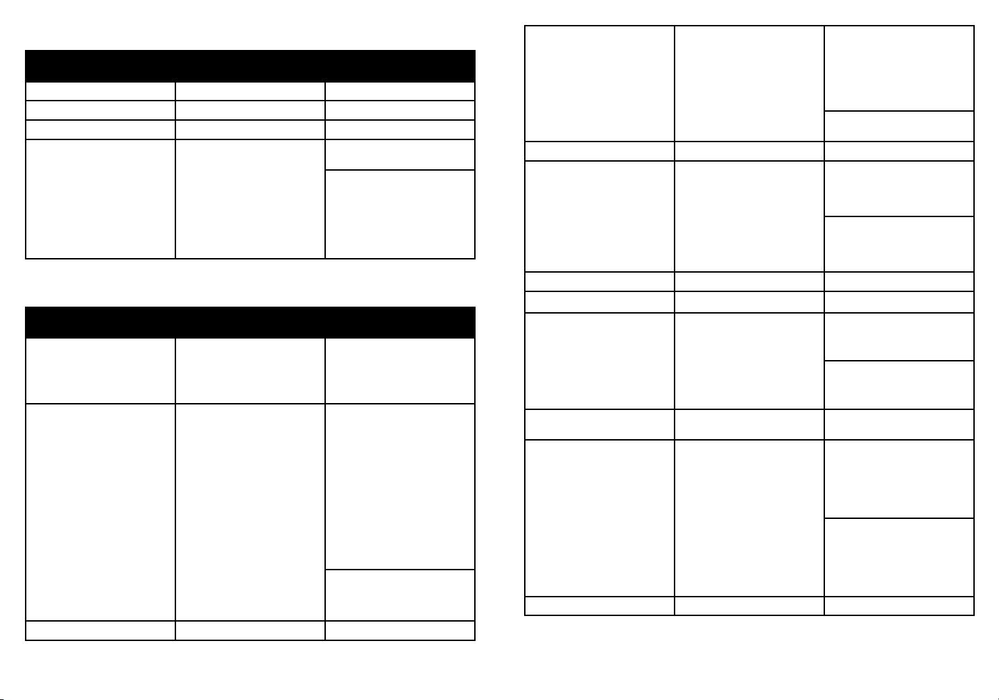
8. SYSTEM CONNECTION:
The following diagram illustrates the typical input and output connection of the splitter:
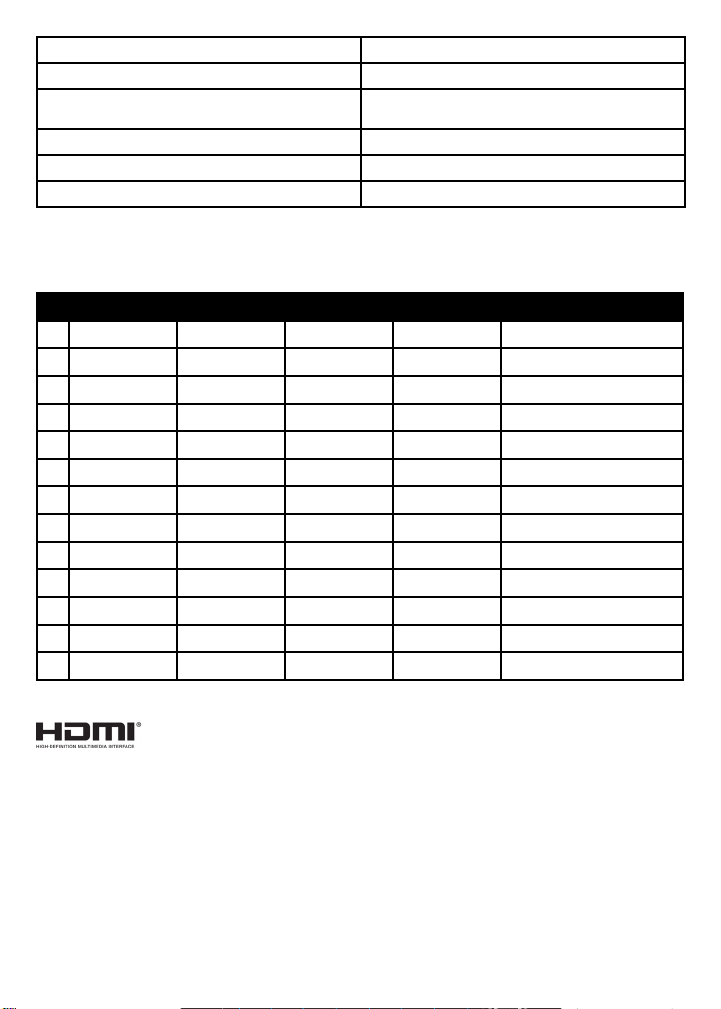
9. TECHNICAL SPECIFICATIONS:
Video Input
Input (1) HDMI
Input Connector (1) Female type-A HDMI
Input Video Resolution Up to 4K@60Hz 4:4:4 8bit, HDR10, Dolby Vision
Output (16) HDMI
Ouput Connector (16) Type-A female HDMI
Output Video Resolution Up to 4K@60Hz 4:4:4 8bit, HDR10, Dolby Vision,
supports 4K to 1080p down-scaling.
HDMI Output Supports up to 5V100mA power for AOC cable.
HDMI Standard V2.0
HDCP Version 2.2
HDMI Audio Signal LPCM 7.1 audio, Dolby Atmos®, Dolby® TrueHD,
Dolby Digital® Plus, DTS:X™, and DTS-HD® Master
Audio™ pass-through.
Analog Audio Output
Output (1) AUDIO
Output Connector (1) RCA (L+R)
Frequency Response 20Hz~20kHz, ±1dB
Max Output Level 2.0Vrms ± 0.5dB. 2V=16dB headroom above-10dBV
(316mV) nominal consumer line level signal
THD+N < 0.05%, 20Hz~20kHz bandwidth, 1kHz sine at
0dBFS level (or max level)
SNR > 80dB, 20Hz~20kHz bandwidth
Crosstalk Isolation < -80dB, 10kHz sine at 0dBFS level (or max level
before clipping)
L-R Deviation < 0.05dB, 1kHz sine at 0dBFS level (or max level
before clipping)
Output Load Capability 1Kohm and higher (supports 10x paralleled 10Kohm
loads)
Noise Level - 80dB
Control
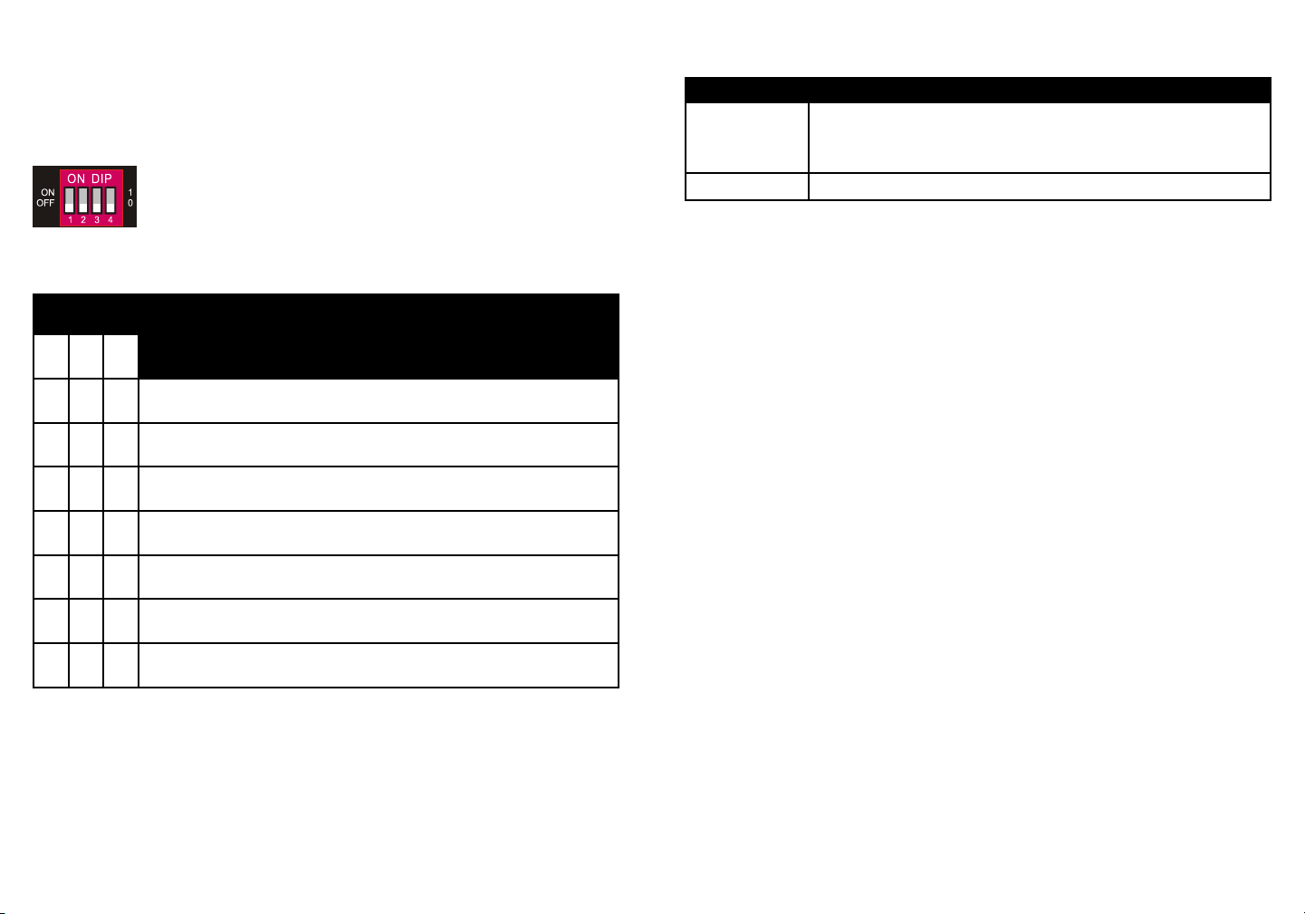
Control Port 1) EDID Switch, (1) FW, (1) RS232
Control Connector (1) 4-pin DIP switch, (1) Micro-USB, (1) Female DB9
General
Bandwidth 18Gbps
Operation Temperature -5 to +55℃(+23° to +131°F)
Amplifier
4K TV
4K
1080p TV
1080p
4K TV
4K
1080p TV
1080p
INPUT AUDIO OUT
RS232
DC 24V
13 14 15 16
1 52 63 7
4 8
910 11 12
OUTPUTS
HDMI:
RS232:
Audio:
Blue-Ray Central Control System

12
Storage Temperature -25 to +70℃(-13° to +158°F)
Relative Humidity 10% to 90%, Non-condensing
External Power Supply Input: AC 100~240V, 50/60Hz; Output: 24V DC
1.25A
Power Consumption 26W(Max)
Dimension (W*H*D) 268mm x 40mm x 125mm
Net Weight 1.14Kg
Video Resolution Down-scaling:
The splitter supports video resolution downscaling, the 4K input can be automatically
degraded to 1080p output for compatibility with 1080p display, shown in the below chart.
Input Output
# Resolution Refresh Color Space Downscale 1080p Specs
1 3840x2160 60Hz 4:4:4 Support 1080p@60Hz 4:4:4
2 3840x2160 50Hz 4:4:4 Support 1080p@50Hz 4:4:4
3 3840x2160 30Hz 4:4:4 Support 1080p@30Hz 4:4:4
4 3840x2160 25Hz 4:4:4 Support 1080p@25Hz 4:4:4
5 3840x2160 24Hz 4:4:4 Support 1080p@24Hz 4:4:4
6 3840x2160 23Hz 4:4:4 Support 1080p@23Hz 4:4:4
7 3840x2160 60Hz 4:2:0 Support 1080p@60Hz 4:4:4
8 3840x2160 50Hz 4:2:0 Support 1080p@50Hz 4:4:4
9 3840x2160 30Hz 4:2:0 Support 1080p@30Hz 4:4:4
10 3840x2160 25Hz 4:2:0 Support 1080p@25Hz 4:4:4
11 3840x2160 24Hz 4:2:0 Support 1080p@24Hz 4:4:4
12 3840x2160 23Hz 4:2:0 Support 1080p@23Hz 4:4:4
The terms HDMI and HDMI High-Definition Multimedia interface, and the HDMI Logo are trademarks or
registered trademarks of HDMI Licensing LLC in the United States and other countries.
Table of contents
Other KanexPro Cables And Connectors manuals