Kangaroo Golf Z-Series User manual

Owner’s Manual
Summer 2019KangarooGolf.com
N:\Kangaroo\Printing\Zseries\Owner’s Manual\Z-series-Owners-Manual-2019.pdf

Table of Contents
Assembly / Disassembly
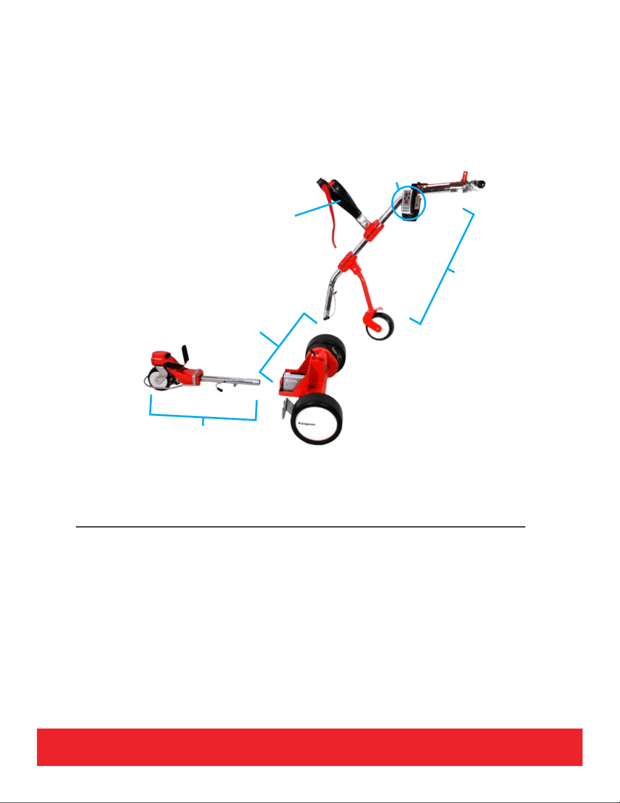
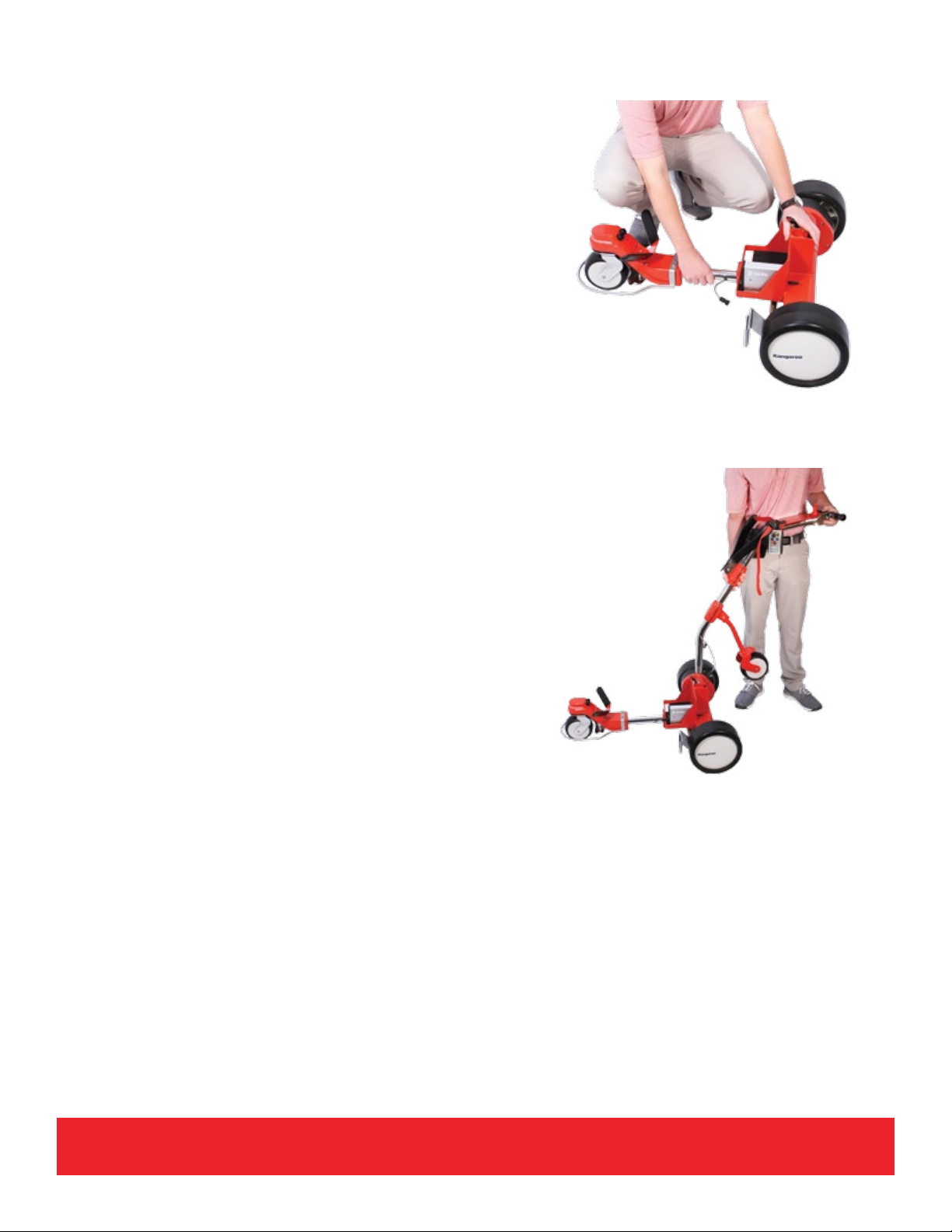
Z-series Assembly / Disassembly..…………..................…..........................................................................…..3
Draw Latches…………………………….........................................….................................................................4
Quick Start Guide...............................................................................................................................................5
Loading your Golf Bag.......................................................................................................................................8
Operation
Modes of Operation………………….......………………….............….....….........................................................9
Free-Wheeling (non-powered).………………………………....................…......................................................10
Power Controls and Manual Mode……....……………….…............................................................................11
Centering Adjustment......................................................................................................................................13
Remote Mode……………………………………..………………….....................................................................14
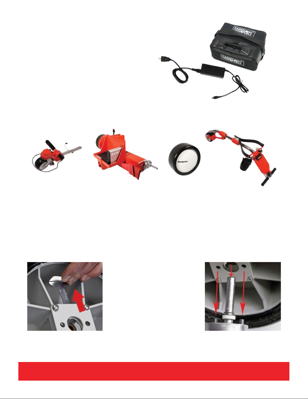
Battery and Charger………………………………..……………..........................................................................17
CaddieCommand and Z-box Care..................................................................................................................18
Ready-Set-GO..……………………………………………………........................................................................18
Maintenance
Routine Care and Maintenance…………………………………..…...................................................................19
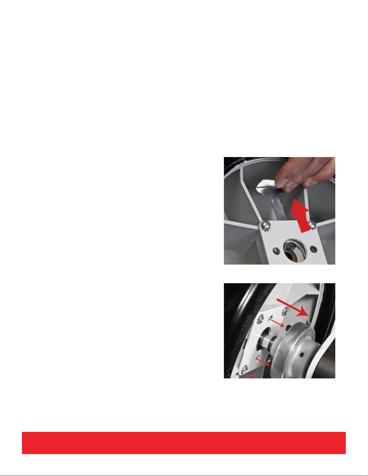
Annual O-ring Replacement……………..………..............................................................................................20
Warranty Information………………………………………....................…..........................................................21
FCC Compliance…………………………………………..............................................................…................. ..22
Timothy Bame
Customer Service
800-438-3011 ext. 2300
Email Timothy at
Contact Us

Z-series Assembly and Disassembly
Your Z-series motor caddie is designed to be disassembled into three sections.
The weight of each standard component of the Z-series is:
Component Weight (LBS)
Steering Structure 10.5
Chassis 26
Upper Caddie Structure incl. Extreme Slope Wheel 12
CaddieCommand Remote Guidance (Including Batteries) 0.75
Battery 5
Charger 1
Tool Kit .2
Handle
Assembly
CaddieCommand
Remote Guidance
Upper Bag
Support
Chassis
Steering
Structure
3

4
Draw latches
The three sections are secured to each other with draw latches as shown.
Note: To avoid possible breakage, always close draw
latches before placing chassis into your car.
If a connection is loose, turn the draw latch metal tension adjustment ring clockwise
to tighten. Don’t over tighten. If draw latch won’t lock into place, loosen it by turning
adjustment ring counter-clockwise. If adjustment ring is difcult to turn, use needle nose
pliers to grip the ring.
metal tension
adjustment ring
To open, pull bottom out
Lift slightly to open
Closed

Quick Start Guide
Step 1: Top-off battery
Attach battery to charger and plug charger
in. Ensure charger light is green to indicate
battery is fully charged.
Step 2: Lay out components
While the battery is being charged, you can
assemble your caddie. Start by laying out
the parts as they will be used.
Step 3: Attach drive wheels to chassis
3a. Remove protective covers from the main axle in the chassis.
3b. On the inside of drive wheels, locate and pull wheel tab, which releases the mechanism
locking wheel to the axle.
3c. Place each wheel on the axle, aligning drive pins on axle with holes in the wheel panel.
3d. Release wheel tab.
5
Pulling the wheel tab.
Inserting the wheel
onto the axle.

6
Step 4: Attach Steering Structure to chassis
4a. Open draw latch under battery tray.
4b. Steady chassis by using the hand-hold at bottom
of battery tray. Insert the steering structure into the
hole in front of battery tray.
4c. Secure draw latch. Draw latches are adjustable if
required.
Step 5: Attach Upper Caddie Structure to chassis
5a. Open draw latch on top of chassis.
5b. Insert handle tube into the hole. Note that
this end of the tube should be vertical when
inserted into chassis.
5c. Secure draw latch.
5e. Remove the three plastic tie-wrap bands from
handle.
Step 4b
Step 5b

Step 6: Attach Wire Plugs to Z-box
6a. Plug in wire from steering structure to receptacle on front of Z-box as shown. Align white
lines on plug and receptacle. Twist locking mechanism on plug to securely attach to
receptacle.
6b. In the same manner, attach wire plug from upper steering structure to receptacle on rear of
Z-box. NOTE: When removing wire plugs from z-box , be sure to twist locking mechanisms
and carefully pull wire plugs from receptacles. Too much force can
damage receptacles.
Step 7: Connect Power, Remote Guidance System Control
7a. Put fully charged battery onto battery tray and attach battery wire harness to chassis power
port.
7b. Attach “T-bar” on battery wire to battery terminals, lining up positive to positive (+) and
negative to negative (-).
7c. Unpack the CaddieCommand remote guidance and familiarize yourself with command
buttons and indicator lights.
7
Step 6a Step 6b
Step 7b

8
Loading your golf bag
Your bag rests on upper and lower bag supports. Pull down ex-adjust bag support (yoke)
until it comes to a stop. Load your bag. Secure with strap and buckle, adjusting the strap if
necessary for a tight t.
If the bag does not t comfortably and securely, there
are two adjustments that can be made.
1. The upper bag support can be slightly widened or
narrowed by pushing gently on yoke arms.
2. The position of yoke on the handle tube is
adjustable, if necessary, to t your bag. Using the
provided Allen wrenches, loosen clamp
and move to desired location. Retighten clamp.

9
Modes of Operation
There are three modes of operation for Z-series.
Free-wheeling: When moving caddie without power.
Manual Operation: Manual mode is handy in close quarters or when a lot of twists and
turns are necessary.
Remote Operation: Remote mode allows you to walk along with your caddie. You can send
it ahead or to the side.

10
Free-wheeling Mode (non-powered)
Free-wheeling allows the drive wheels on your Z-series to turn freely without engaging the
axle or drive train. If you need to pull or push your caddie without power, always put it in
Free-wheeling mode rst. This prevents strain on gears.
If the caddie is difcult to push or pull, you’re not in free-wheeling mode. For very short
distances, you can safely move the caddie wheelbarrow style by lifting the handles so that
only the front wheel is on the ground while in motion.
Putting wheels in Free-wheeling mode
Pull release tab on inside of the wheel toward the tire.
Slide wheel outward slightly on the axle. Release tab
to allow it to lock in the proper groove. When the hub
is locked onto the free-wheel groove, the wheel will not
slide off. Repeat this process for other wheel.
Returning Caddie to Axle Drive
For each wheel, pull release tab and slide the wheel
inward, aligning drive pins on the hub with holes in
wheel. Release tab to securely mount wheel on axle.

11
Power Controls and Manual Operation
Function Switch: 3-way toggle function switch
serves as power ON/OFF and determines mode of
operation between manual and remote.
OFF (neutral position): You should put your caddie
in OFF when you are away from it or waiting for a
period of time. This will preserve the longevity of
the battery and prevent mishaps.
Manual: “Manual” refers to hands-on steering and
operation of the caddie. However, it will proceed
at the speed selected even if your hands are not on the handles. We recommend manual
mode when in parking lots and tight areas or near water hazards and other carts.
Remote: Once function switch has been toggled to “Remote”, speed and direction is
controlled by keypad commands on the CaddieCommand remote.
speed
control
function
switch
scorecard
platform

12
Speed Control
The speed control is located between the
handle grips. When starting either manual
or remote mode, it is recommended that the
speed be set so that the white bar indicates
a typical walking speed.
When you turn power on, there will be a gradual acceleration to the set speed. To avoid
runaways we recommend starting at a low speed before turning on the power. If the speed
is set all the way down, the unit is still powered, but will not move.
Once you are under way, set the speed to suit your walking pace.
Auto Brake and Downhill Travel
Much like an automobile can be slowed by shifting to a lower gear, the caddie can be
slowed down by slowing the speed setting when it is accelerating downhill due to gravity.
If the slope is extremely steep, turning the function switch OFF as you go downhill will slow
the caddie down.
When stopping on a hill, turn the caddie
sideways. There is no “parking brake”.

13
Extreme Slope Wheel
When going uphill, the extreme slope wheel will
swing away from the upper caddie structure to
support the weight of the caddie and golf bag. It
isn’t neccessary for you to pull it out in advance.
Provides added stability, preventing backward
tipping.
Centering Adjustment
The track of your Z-series, when you’re not turning, is controlled with a knob on the front
cover of the Z-box. If you nd that your caddie is moving off center, you will need to make
an adjustment. To do this, make very small adjustments and test the track of your caddie
again. Turn it as you would a steering wheel in the direction that you want the front wheel
to move toward.

14
Remote Operation
There are three important components of remote control operation: CaddieCommand
remote guidance system (remote), Z-box, and steering structure. The remote and Z-box
communicate with each other to command and provide feedback.
A motor changes the front wheel’s direction in response to directional commands. GO,
STOP, and speed commands operate the main drive wheels in the same way as in manual
operation.
Kangaroo’s front wheel turning design, the Steering Structure, guarantees smooth and
predictable turning of the motorcaddie.
CaddieCommand is designed for easy one-handed operation. CaddieCommand is only
operational when the function switch is set at REMOTE. Pointing it at the caddie is not
necessary but will provide the best range for the signal. Trees, cars, and other objects
can negatively impact the range. There are pressure buttons for speed and direction
commands and three signal lights.
Remote control components use the 900-megahertz band, and have been tested and
approved by the FCC (USA) and IC (Canada) (See page 22 for additional information). Band
provides range and realiability benets beyond that offered by the competition. In addition
to many other control functions, the radio receiver and antenna are included in the Z-box.

15
Battery compartment is located on the bottom rear of case. It takes two high quality
standard AA batteries. These batteries should last approximately three months under
normal conditions. Replace them at rst sign of weakness as indicated by amber light on
the key pad.

16
GO – Caddie will proceed at the speed selected on the red speed control.
FAST – Caddie will go at the fastest speed available. To return to selected
speed, press GO.
LEFT– Caddie will turn left at an angle of 20° for as long as button is
depressed. It will stop turning and go straight ahead from that position
once button is released.
RIGHT - Caddie will turn right at an angle of 20° for as long as button is
depressed. It will stop turning and go straight ahead from that position
once button is released.
STOP – The caddie will stop. Note that this does not reposition the
Function Switch to “OFF”. If you will not be driving the caddie for a while,
such as stopping to take a shot, you should turn the Function Switch to
OFF.
Amber Lo Batt- This light will ash when batteries in your CaddieCommand are low and
should be replaced. To test your batteries, press any command button.
Red Stop Command Conrmation – This light will ash to indicate that a stop command
has been given.
Green GO Command Conrmation - This light will ash to indicate that a GO command
has been given.

17
Safety Shut-off (after 15 seconds)
There are two potential risks that are mitigated by the Safety Shut-off feature.
• You or your caddie have moved so that it is now out of range of the
CaddieCommand.
• You are distracted or otherwise not aware of where your caddie is going.
To prevent these situations from becoming accidents, the remote guidance system will
automatically stop the caddie if a command hasn’t been given in 15 seconds. While this
may seem like a short time, the vast majority of owners nd that they’re interacting with
their caddie frequently, changing direction, speed, starting and stopping.
Performance Specications for Remote Operation
It’s benecial to know the operating parameters for your Z-series:
• Maximum time between commands (safety shut-off) : 15 seconds
• Maximum range for Go/Stop/Speed commands: 100 yards
• Maximum range for directional commands: 100 yard
• Turning angle: 20°
• Turning radius on pavement: 16 feet
• Time lapse from straight ahead to full turn: 2 seconds
• Time lapse from turn to straight ahead: 2 seconds
Battery and Charger
Z-series is powered by a CaddyCell lithium Ferro phosphate battery. For battery and
charger instructions, click here.

18
Care of CaddieCommand and Z-box
Care should be taken around water. The enclosures are water resistant, but won’t
withstand being submerged or placed in a wet area for an extended period. Exposing
these units to water will void their Warranty. During the off season, store CaddieCommand
in a dry place and remove AA batteries to protect it from corrosion due to battery leakage.
Ready-Set-Go
In Manual
To proceed with your Z-series in manual mode:
1. Set speed to safe or preferred walking speed on speed control.
2. Set function switch to Manual. Caddie will start moving.
3. Adjust speed control if necessary.
4. Steer with handle bar. You may let go of the caddie, but do not let it get out of
reach!
To discontinue Manual mode:
1. Set function switch to OFF.
In Remote
To proceed with your Z-series in remote mode
1. Set speed to safe or preferred walking speed on speed control.
2. Set function switch to Remote.
3. Press GO button on CaddieCommand. Caddie will start moving.
4. If Amber Low Battery light comes on, replace the CaddieCommand’s two AA
batteries.
5. Adjust the speed using thumb-wheel speed control on the handle.
6. Use STOP, FAST, RIGHT and LEFT buttons as required.
7. Press any button every 15 seconds to continue in motion.
To discontinue remote mode:
1. Depress STOP button.
2. Set red function switch to OFF or manual.

19
Routine Care and Maintenance
Like any piece of mechanical equipment, your Z-series will benet from a small amount of
care and making sure that others who handle it know what to do.
Lubrication
In general, your Z-series will not need lubrication. This is assisted by keeping it clean of
dirt and debris. If you feel it’s necessary, use only a silicone or Teon based product. Oil
based products such as WD40 will attract dirt and make problem worse. Clean anything
you can access before applying lubrication.
Keep it Dry and Clean
It goes without saying that you should not drive your Kangaroo into a water hazard, even
though there have occasionally been stories of one surviving such treatment.
If you do get the CaddieCommand remote or the Z-box wet, treat it like you would your
mobile phone, dry off what you can and put it in a container with an absorbent material
such as uncooked rice.
Periodically clean out plugs and receptacles by blowing
out debris and dirt with electronic device canned air.
Looking Good
Your Z-series will always look its best with occasional
cleaning. Finished components can be cleaned with
soap or mild detergent and water, being especially
careful to keep electronic and electric components
and plugs dry. A good quality automative wax will make the task easier and keep stainless
and nished surfaces clean longer. Tires may become too slippery if cleaned with some
cleaners. DO NOT hose down or pressure wash your caddie!

20
Normal Wear and Tear
Handle grips, upper and lower bag protectors, yoke strap, draw latches and tires may wear
out with use. This is considered normal and not covered by warranty. Replacements are
available through Kangaroo Golf at nominal cost.
Annual O-ring Replacement
The only periodic maintenance that is expected on your Z-series is replacement of an
O-ring, which is attached to a motor in the steering structure.
Remote steering is accomplished by the movement of this specially designed neoprene
O-ring against the front wheel fender channel. It is important that the O-ring grip the
channel rmly. Be sure not to lubricate the O-ring or this channel. Off the shelf O-rings from
hardware stores may not be compatible.
Normal use will eventually cause O-ring wear or deterioration. The most obvious indication
of O-ring deterioration is sluggish or unresponsive steering. Kangaroo recommends
this part be replaced annually. The O-ring is a “wear item” and is not covered by factory
warranty.
For detailed O-ring replacement Instructions, click here.
Table of contents
Other Kangaroo Golf Golf Trolley manuals