Kangke SK-50 User manual

SK-50
ARF
ASSEMBLY MANUAL
Kangke Industrial USA, Inc. 65 East Jefryn Blvd. Deer Park NY 11729
http://www.kangkeusa.com E-mail: [email protected]
Tel: 1-877-203-2377 Fax: 1-631-274-3296

Congratulations!
Kangke Industrial USA, Inc. brings you one of the finest ARF fun-fly models available. Skilled
craftsmen combined with top grade materials and precision jigs have all come together to produce an
aircraft with outstanding flight qualities. If you follow the directions carefully the performance of this
aircraft will surely please you.
Specifications:
Length 49 in.
Wing Span 56 in.
Area 671 sq. in.
Weight 5.5-6.0 lbs.
Engine 40-52 2 Cycle
Kit Contents:
Fuselage 1
Wing panel 2
Ailerons 2
Cowling 1
Canopy 1
PACK 1
Stabilizer 1
Elevator 2
Fin 1
Rudder 1
PACK 2
Dihedral brace 1
Servo tray 1
PACK 3
Fuel tank 1
Wheels 2
Tail gear 1
Tail wheel 1
Control horn 5
Control wire 6
Control rod 2
Motor mount 1
Hardware pack 1
Pack 4
Manual 1
Decal kit 1
Wheel Pants 2
The following additional
items will also be needed to
build the SK-50
HOBBY ITEMS:
4 oz. 30 min. epoxy
Popsicle sticks
Hobby knife
Thin CA .5 oz
Med. CA 1 oz.
Radio 4-channel min.
5 servos
Fuel line 10-inches
Motor (Tiger Shark .40/52)
Muffler
Spinner (Super Kraft 2.25”)
HOUSEHOLD ITEMS:
Paper towels
Alcohol
Masking tape
Ruler
Felt tip pen
Screwdrivers
Pliers
Sewing thread
5/32 drill
1/8 drill
1/16 drill
Read each step of the instructions carefully. Be sure you understand what is required and what the
procedure is before you glue or cut anything. How well you assemble this model will have a direct effect
on its flight characteristics.
This manual is the sole property of Kangke Industrial USA, Inc. Reproducing any part without the
consent of Kangke Industrial USA, Inc. is a lawful violation.
Warranty: Kangke Industrial USA Inc. guarantees the kit to be free of defects in both material and workmanship at the date of
purchase. This warranty does not cover any parts damaged by use or modifications. In no case shall Kangke Industrial’s liability exceed the
purchase cost of this kit. Since Kangke Industrial has no control of final assembly and material used by user for final assembly, no liability
shall be assumed or accepted for any damage resulting from the use by user of final user-assembled products. This kit has been flight test for
normal use. If the plane will be used for extremely high stress flying, the modeler is responsible for reinforcing the high stress points.
Inspect this kit immediately after receiving it, report any missing and damaged parts within 7 business days otherwise the claim may be
denied.
2

WING ASSEMBLY
Remove the tape from the servo wire pull string at
the center of the wing. Work the string through the
exit hole in the wing bottom and secure.
Measure the dihedral brace, locate and mark its
center.
Trial fit the dihedral brace in its box in both wing
panels. The “V” shape of the brace points down to
produce positive dihedral. The brace should have
a snug fit, sand lightly if necessary.
The following steps must be done quickly before
the epoxy has time to set up. Read the procedure
and gather the materials before starting.
Mix a small amount of 30-minute epoxy. Spread
the epoxy in the dihedral box top, bottom, and
sides about 1 inch in on both wing panels. The
snug fit of the brace will push it down the box.
Apply epoxy to one half of the wing spar and slide
it into position. Spread the epoxy that oozes out
over the wing mating surface as well as the other
half of the wing spar. Slide the other wing panel in
place, wipe off the excess epoxy with a paper
towel moistened with alcohol.
Stretch masking tape across the joint in such a
way as to apply pressure to the joint. DO NOT
DISTURB THE WING UNTILL THE EPOXY HAS
FULLEY CURED.

FUSELAGE ASSEMBLY
Open the two elevator and the right side rudder
control rod slots. The slots can easily be found by
shining a flashlight down the inside of the
fuselage.
Locate and mark the center of the firewall on the
top of the fuselage.
Remove the elevators from the stabilizer. Center
the stabilizer in the fuselage. Insert a pin in the top
of the firewall at the center mark. Using a piece of
string go back and forth between the ends of the
stabilizer adjusting it till it is centered and square
to the fuselage. DO NOT GLUE
Use a felt tip pen to mark the outline of the
fuselage on both the top and bottom of the
stabilizer. Remove the stabilizer. Cut through the
covering about 1/8-inch inside the lines and
carefully remove the covering exposing the wood.
{Be careful not to cut into the wood, as this would
weaken the structure}
Slide the stabilizer back into the fuselage, leaving
3/8-inch of bare wood exposed. Coat the wood top
and bottom with epoxy, slide the stabilizer
through the fuselage exposing the wood on the
other side, and coat the wood with epoxy. Center
the stabilizer and use the string as before to verify
its alignment. Wipe the excess epoxy with a paper
4

towel moistened with alcohol. Allow to cure
before proceeding.
Remove the rudder from the fin. Coat the inside of
the fin slot, as well as the top of the stabilizer in
the slot with epoxy.
Push the fin in the slot until it bottoms against the
fuselage. Wipe off excess epoxy with a paper
towel moistened with alcohol.
Test fit the servos in the mounting tray, do not
mount them at this time.
Fit the servo-mounting tray to the inside of the
fuselage, sand if necessary for a snug fit between
the fuselage sides as well as the fuselage
bulkheads. Be sure the single servo hole is to the
front.
Sand the last inch of the throttle wire outer casing
just enough to roughen the surface. Coat the
surface of the casing with epoxy and slide it
through its hole in the firewall, as well as the fuel
tank opening inside the fuselage leaving 3/8-inch
exposed.
Install the motor mount beams using the supplied
2.5mm screws.
5

Trim and sand the mating edge of the cowl for
best fit. Tape the cowl securely to the fuselage.
Using a 1/16-inch drill, make two holes on each
side 1/2-inch in from the corners and 1/8-inch
forward of the rear edge.
Before removing the cowl use a ruler to measure
the distance from the firewall to the front of the
cowl. Record this number for use later.
Remove the cowl.
Using a 1/8-inch drill enlarge the holes in the cowl
only.
Temporarily install the spinner on the front of
your motor. Add 1/4-inch to the measurement
taken before, this is the distance to the back of the
spinner. Set the motor on the mount making sure
the distance to the firewall is correct, and the
motor is centered and straight between the rails.
When satisfied mark the motor mounting
locations, remove the motor and drill the mounting
holes using a 1/8-inch drill.
FUEL TANK
Pass the two metal tubes through the silicone
stopper. Place the large endplate on the outside
and the small endplate on the inside. Press the
screw through the outer plate and through the
silicone stopper, screw it into the inner plate do
not tighten. Slide the metal tubes so 1/2-inch
extends past the outer side of the silicone stopper.
Gently bend the long tube up to point into the
“bubble” at the top of the tank. Push the flop
weight into one end of the silicone tube. Cut the
tube so that when the other end is pushed on the
short metal tube the flop weight will be
approximately 3/8-inch from the back of the tank.
Slide the assembly into the tank, making sure to
6

get the vent tube in or near the “bubble”. Tighten
the screw until the stopper is tight in the opening.
It is best to label the vent and carb lines with a felt
tip marker on the outer plate to avoid confusion
later.
Place a 1/4-inch bead of RTV type silicone around
the tank stopper. Carefully slide the tank into
position through the fuselage. Press it gently
against the back of the firewall
Apply a small amount off RTV silicone around the
tank at the fuselage bulkhead. Do not make one
continuous bead, as the silicone is used as a
vibration absorber. Several small spots will work
better and be lighter.
LANDING GEAR
Install the tail wheel bracket using the three
supplied screws. Make sure the control arm is on
the centerline of the rear of the fuselage. A small
notch will need to be cut to allow space for the
support bearing.
Slide on the tail wheel. Press the retaining tube on
the axle and secure with one small drop of thin
CA. {Be sure not to get any CA on the wheel}
Install the main gear with the four supplied screws
7

and washers. Be sure when the gear is installed the
straight edge is to the front.
Drill one of the axle holes in each wheel pant {be
sure to make a right and left side}. Slide a wheel
collar on the axle followed by the wheel and a
second collar. Tighten the lock screw in the
outside collar. Place a washer on the threaded
portion of the axle and install the assembly in the
wheel pant. {The wheel pant is made from a very
flexible material and will not break during this
step}
Slide the axle through the gear, install a washer
followed by the supplied lock nut. Hold the axle
with pliers, align the wheel pant and tighten the
lock nut.
CONTROL SURFACES
Set the fuselage on its wheels. Align the top of the
rudder with the top of the fin. Mark the leading
edge of the rudder at the tail wheel steering arm.
At the mark drill a 1/16-inch hole straight into the
rudder 3/4-inch deep.
Mix a small amount of epoxy, using a toothpick
work the epoxy into the hole. Slide the tail wheel
steering arm, rudder and hinges into place. Apply
one drop of thin CA to each side of the hinges.
8

The CA will “wick” into the wood and secure the
hinge, only one drop is necessary.
Use the same procedure for all the remaining
control surfaces. Line up the edges carefully and
apply one drop of thin CA to each side of the
hinges.
SERVOS / CONTROLS
Install the servos in the servo tray following the
radio manufactures instructions. Cut the throttle
control casing 1/2-inch behind the fuel tank.
Install two 6-inch pieces of fuel line on the tank
carburetor and vent tubes. Install the motor using
the four supplied screws washers and lock nuts.
Make a “Z” bend at one end of the throttle control
wire. Install the “Z” bend in the carburetor. Slide
the other end of the throttle
control wire through the outer casing and place the
carburetor on the motor. Do not tighten. Bend the
wire slightly till throttle operation is smooth and
does not bind.
Temporarily hook up the receiver and battery,
power everything up and center all the servos. Pull
the throttle trim to the off position and the throttle
stick to idle. With the carburetor fully closed mark
the location of the servo arm hole on the control
wire.
9

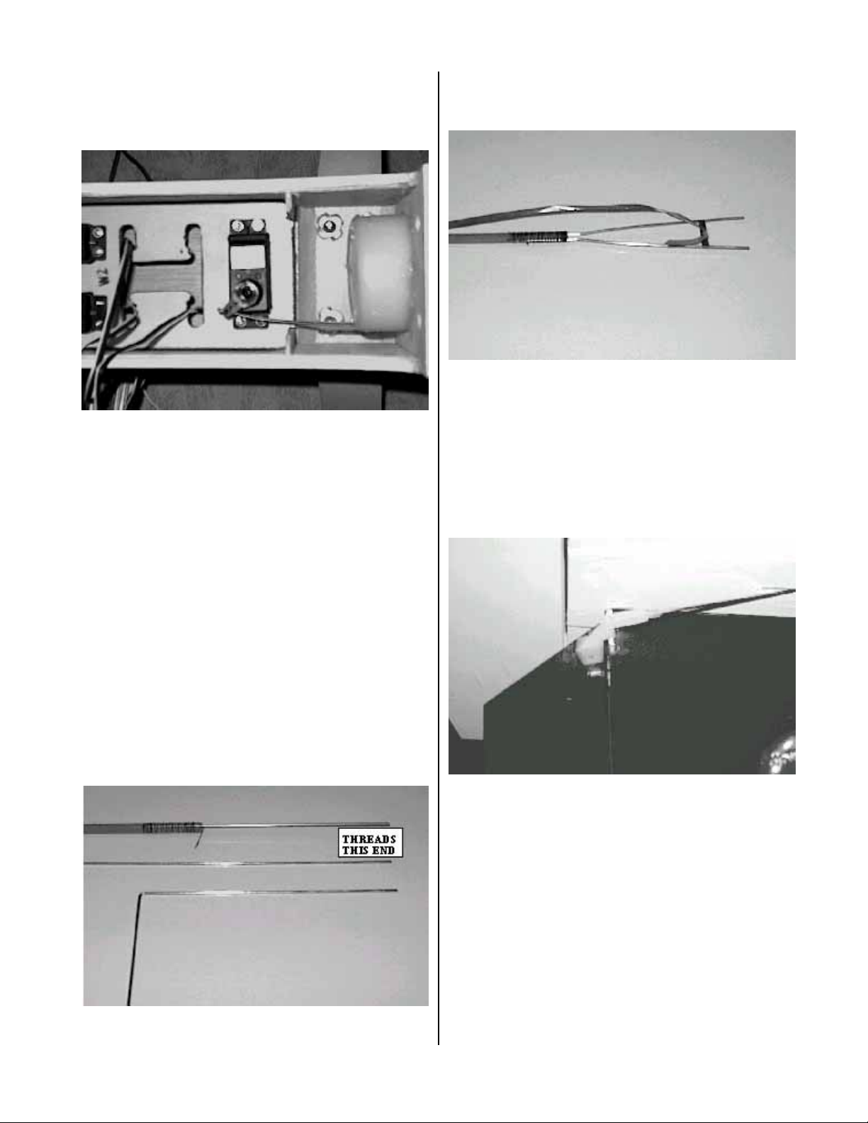
Make a “Z” bend in the control wire and install
the servo arm. Adjust as necessary for proper
operation. A slight bend in the control wire may be
necessary for smooth operation.
Locate the two control rods. The one for the
elevator has two holes in one end, one hole in the
other. The one for the rudder has one hole in each
end. Make a 90-degree bend in three of the control
wires 6 ½-inches from the threaded end. Cut the
wires just past the bend leaving 1/8-inch. Press
two of these wires into one end of the elevator
control rod squeeze gently with pliers then wrap
tightly with thread. Soak the thread with CA.
Repeat this process in one end of the rudder
control rod. Bend one more wire 6 ¼-inches and
cut in the same manner as before. Install this wire
in the other end of the elevator control rod. For the
other end of the rudder control rod make the wire
10 inches. The two wires on the elevator control
rod now need to be spread apart. Make two equal
bends, one in each wire 3/8-inch from the end of
the wood rod. Bend the wire until the threaded
ends are 2 ¾-inches apart.
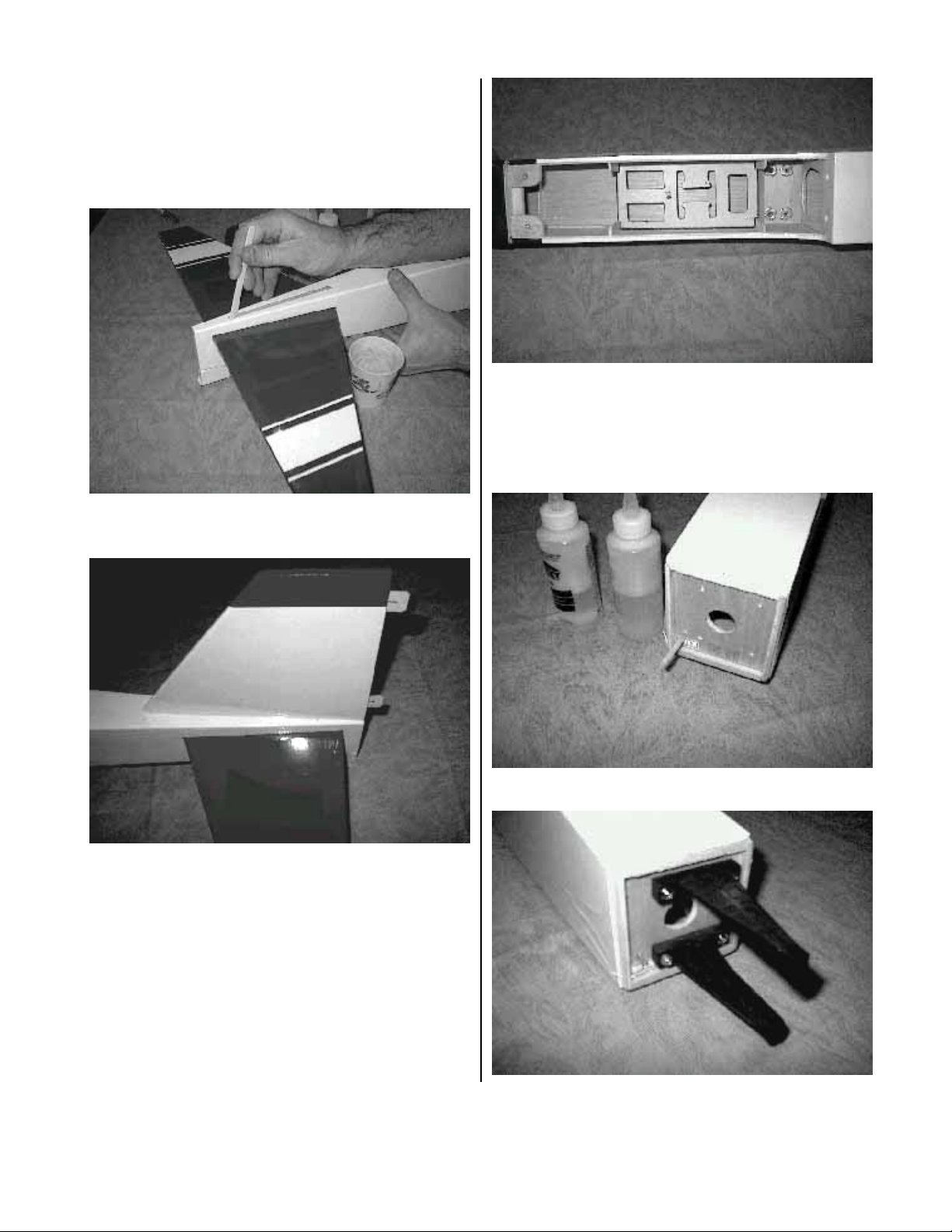
To insert the control rod into the fuselage, tie a
string around the fork and pull the ends together as
shown. Slide the control rod into the fuselage, line
the wires up with the fuselage slots and pull the
string to release the wires through the slots.
Screw a clevis on each wire of the elevator till
about 1/8-inch of thread remains exposed. Place a
control horn in the clevis and with the control
surface straight locate the control horn so the
adjustment holes are inline with the leading edge
of the control surface. Install the control horn in
this location using the provided screws and
backing plates. Repeat this procedure for the
rudder
Screw a clevis on the servo end of the elevator
control rod. With the servos centered and the
control surfaces straight adjust the clevis and
install on the servo arm. Mark the rudder wire and
install in the same manner using a “Z” bend.
10

Begin the wing servo installation by checking the
length of the servo wire; add an extension if
necessary. Be sure to tape the connectors for the
extension to prevent them from unplugging in the
wing. Using the servo wire pull string, work the
wire through the wing. Mount the servo following
the manufacture instructions.
Center the servo and install a control arm. Mount
a
control horn on the aileron so the control wire is
parallel to the center seam of the wing. Mark the
wire and install with a “Z” bend as before. Repeat
the process for the other wing servo.
FINAL ASSEMBLY
Tighten the carburetor and install the cowl,
propeller and spinner.
Hook up the fuel and vent lines.
Install the receiver and switch following the
manufacture instructions. Hook up the wing servo
leads and install the wing.
Trim and install the canopy. The canopy may be
held on with the provided screws or as an
alternative canopy adhesive may be used.
BALANCE
The center of gravity must be located from 2.3/4
to 3.1/4-inches behind the leading edge of the
wing. Moving it to the forward side of the range
will increase the stability of the aircraft, moving it
11

aft will increase control response. We recommend
the forward position for initial flight tests.
CONTROL THROWS
Double check all controls move in the proper
direction
With your radio on, center all trims and adjust the
clevises so all control surfaces are straight.
Measure the control surface movement at the
widest part of each surface. Use the servo horns
and bell crank holes to adjust the control throw.
For your first flights the control throws should be
set to the following:
Elevator 1/2-inch up / down
Rudder 1 ½- inch right / left
Aileron 1/4-inch up / down
MOTOR SET UP
Be sure the motor is properly broken in using the
manufacture instructions. Set the throttle throw to
shut the motor off when the trim is pulled down
and idles reliably with the trim up.
After the motor is set, run one tank of gas at full
throttle, measure how much time it takes to run the
tank dry.
CONGRADULATIONS you are now ready for test
flights.
Before leaving for the field be sure your batteries
are fully charged and you have all the required
support equipment {fuel, starter, glow driver,
ect.}.Although the SK-50 will fly well in wind,
wait for a nice day.
At the field have a helper hold the airplane,
following the radio manufactures instructions
perform a range check of the radio. Do this with
the motor off, start the motor and do it again.
Perform this test EVERY TIME YOU GO TO FLY!
TRIMING BASIC FLIGHT
The SK-50 is NOT a trainer. A true aerobatic
aircraft, it goes only where you point it and will
not recover to level flight without control input. If
you do not have high performance experience seek
the help of someone who does.
Line up on the center of the runway and slowly
open the throttle, using the rudder to maintain
directional control. Once the tail is up apply a
little up elevator and allow the plane to gently lift
off the runway. Keep the climb angle and turns
shallow until you reach a safe altitude. Reduce the
throttle to about 60% power. With the airplane
flying away from you adjust the radio aileron trim
tab till the wing stays level. Turn and line up the
plane with the runway. Adjust the elevator trim till
the plane maintains level flight. Once again with
the airplane flying away from you adjust the
rudder trim till the fuselage tracks straight {it may
be necessary to correct the aileron trim after this
procedure}. Continue to fly and trim until the
aircraft is tracking well, land before the fuel runs
out. Carry a little power on final approach until
over the end of the runway, then cut power to idle,
hold the plane just off the runway till the airspeed
bleeds off and the plane settles on. If the landing is
too long add power go around and try again, don’t
try to force it to the ground.
Now its time to zero out the trims. To do this
measure the control location, center the trim tab
on the radio and adjust the servo horn for large
changes, the control clevis for small changes. For
example if after the flight the rudder is 3/16 inch
to the right, center the radio trim and adjust the
clevis till the rudder once again measures 3/16
right. By doing this whenever you fly, setting the
radio trims at center will result in a well-trimmed
plane. Increase the control travel, as you become
more familiar with the flight characteristics until
loops take about 50 feet and knife edge can be
maintained with 80% stick deflection. Final roll
rate should be 300-360 degrees per second.
If you have followed the procedures in this
Manuel you will now be rewarded with one of the
finest flying sport models available. All primary
aerobatic maneuvers are at your fingertips and
the aircraft will perform them with ease.
12
Table of contents
Other Kangke Toy manuals
Popular Toy manuals by other brands

Hangar 9
Hangar 9 Sundowner 36 ARF Assembly manual

Mattel
Mattel Disney Pixar Toy Story Buzz Lightyear Space Ranger... instructions

Enabling Devices
Enabling Devices Rockin' Robbie user guide

LeapFrog
LeapFrog My Discovery House Parent guide & instructions

Eduard
Eduard Zoom Il-2m3 Stormovik quick start guide

Topmodel
Topmodel Scale Series manual

Eduard
Eduard Wellington GR Mk.VIII landing flaps Assembly instructions

TRANSFORMERS
TRANSFORMERS CYBERVERSE POWER OF THE SPARK SCRAPLET instructions

marklin
marklin Langenschwalbacher-Wagen instruction manual

marklin
marklin ICE 2 instruction manual

LeapFrog
LeapFrog Click Start Disney Pixar Finding Nemo sea of... Parent guide & instructions

Trix
Trix BR 132 manual