Kanmor Mixing Control 362e User manual

- Data Brochure
Mixing Control 362e
D 362e
06/03
1 of 32 © 2003 D 362e - 06/03
The Mixing Control 362e is a microprocessor based control designed to pro ide a reset mixed supply water temperature to
a heating system based on outdoor air temperature. Multiple zone temperature control can be achie ed by using either a
con entional thermostat system or by using kanmor Zone Controls attached to the 362e. For single zone heating applications, a
single Room Temperature Unit (RTU) can be connected directly to the 362e for zone temperature control.
The 362e incorporates a large Liquid Crystal Display (LCD) in order to pro ide system status and operating information. The
same LCD is used when setting up and installing the control. Standard features include boiler return protection, intelligent boiler
operation, Warm Weather Shut Down (WWSD), and pump exercising. As well, with the addition of a new Monitor feature, it is now
possible to track pump and boiler running hours, boiler cycles and high and low sensor temperatures.
The 362e uses a floating action output signal to control the position of a mixing al e.
Output
Mixing Val e &
Actuating Motor
Output
Boiler
Output
Mixing
System
Pump
M
Input
230 V (ac)
Power
Supply
Input
Outdoor
Sensor
Included
Input
Uni ersal Sensor
Included
Input
Uni ersal Sensor
Included
Input
Mix
Demand
signal
Input
kanmor
timer
Input
Room
Temperature
Unit (RTU)
Input
Remote
Display
Module (RDM)
OR
H11XXA
NLPmp tN2 Sw
Mix tN1/ Com 10K UnO Com Mix Boil
Out
1 2
Mix
Pwr Opn Cls
1034 5 6 7 8 9 11 12 13 14 1615 17 18
Mixing Control 362e
Floating Action
Do not apply power
Signal wiring must be rated at least 300 V.
Power
Mix
Demand Boiler
Menu Item
Mix Demand
WWSD
Minimum
Maximum
Test
off not testin
red testin
red testin paused
For maximum heat,
press and hold Test
button for 3 seconds
Setback
None
INSTALLATION CATEGORY II
Made in Canada
Power: 230 V ±10% 50/60 Hz 2300 VA
Relays: 230 V (ac) 10 A 1/3 hp, pilot duty 240 VA
Demand: 20 to 260 V (ac) 2 VA
Input
kanmor Slab Sensor, or
Indoor Sensor or Zone Control
OR OR

© 2003 D 362e - 06/03 2 of 32
How To U e The Data Brochure
U er Interface
Table of Content
Control Setting ..............................................Pg 17
View Menu ..............................................Pg 17
Adjust Menu ...........................................Pg 18
Schedule Menu ......................................Pg 20
Miscellaneous Menu .............................Pg 20
RTU Menu ...............................................Pg 20
Te ting and Trouble hooting ........................Pg 23
Monitor Menu .........................................Pg 25
Error Messages......................................Pg 26
Technical Data ................................................Pg 32
Limited Warranty ............................................Pg 32
U er Interface..................................................Pg 2
De cription of Di play Element ..................Pg 3
Sequence of Operation..................................Pg 4
Section A: General Operation..............Pg 4
Section B: Mixing Reset .......................Pg 5
Section : Boiler Operation .................Pg 9
In tallation.......................................................Pg 11
Electrical onnections..........................Pg 12
Testing the Wiring..................................Pg 14
DIP Switch Setting ........................................Pg 16
Acce Level .................................................Pg 16
This brochure is organized into four main sections. They are: 1) Sequence of Operation, 2) Installation, 3) Control Settings, and
4) Troubleshooting. The Sequence of Operation section has three sub sections. We recommend reading Section A: General
Operation, as this contains important information on the o erall operation of the control. Then refer to the sub sections that apply
to your installation.
The Control Settings section of this brochure illustrates the menu screens that are built into the control. These menu settings are
referenced to the specifi c section in the Sequence of Operation.
The 362e uses a Liquid Crystal Display (LCD) as the method of supplying information. You use the LCD in order to setup and
monitor the operation of your system. The 362e uses four push buttons (Menu, Item, ▲, ▼) for selecting and adjusting settings.
As you program your control, record your settings in the actual settings column of the Adjust Menu. The table is found in the
second half of this brochure.
Menu
All of the items displayed by the control are organized into arious
menus. These menus are listed on the left hand side of the display
(Menu Field). To select a menu, use the Menu button. By pressing
and releasing the Menu button, the display will ad ance to the
next a ailable menu. Once a menu is selected, there will be a
group of items that can be iewed within that menu.
Item
The abbre iated name of the selected item will be displayed in the
item field of the display. To iew the next a ailable item, press and
release the Item button. Once you ha e reached the last a ailable
item in a menu, pressing and releasing the Item button will return
the display to the first item in the selected menu.
Adjust
To make an adjustment to a setting in the control, begin by
selecting the appropriate menu using the Menu button. Then
select the desired item using the Item button. Finally, use the
▲ and / or ▼ button to make the adjustment.
Additional information can be gained by obser ing the Status field of the LCD. The status field will indicate which of the control’s
outputs are currently acti e. Most symbols in the status field are only isible when the View Menu is selected.
Menu Item
Menu Item
Menu Item

3 of 32 © 2003 D 362e - 06/03
Di play
Symbol De cription
The following defined terms and symbols are used throughout this manual to bring attention to the presence of hazards of arious
risk le els, or to important information concerning the life of the product.
- Warning Symbol: Indicates presence of hazards which can cause se ere personal injury, death or
substantial property damage if ignored.
- Double insulated
- Local le el, appliances
INSTALLATION
CATEGORY II
Definition
Pump
Displays when the mixing pump is turned on.
Burner
Displays when boiler relay is turned on.
Boo t
Displays when the control is in boost after
setback.
Occupied Schedule
Displays when the control is in occupied
mode.
UnOccupied Schedule
Displays when the control is in unoccupied
mode.
Lock / Unlock
Displays whether the access le els are
locked or unlocked.
Warning
Displays when an error exists or when a limit
has been reached.
Pointer
Displays the control operation as indicated
by the text.
°F, °C, min, hr, ec
Units of measurement.
Override
Displays when the control is in o erride
mode.
Open / Clo e
Displays when the actuator is opening or
closing the mixing al e.
UnOcc
Occ
Item Field
Displays an abbre iated
name of the selected item
Menu Field
Displays the
current menu
Statu Field
Displays the current
status of the control
inputs, outputs and
operation
Number Field
Displays the current alue
of the selected item
Button
Selects Menus,
Items and
adjusts settings
}
Mix Demand
WWSD
Minimum
Maximum

© 2003 D 362e - 06/03 4 of 32
Section A
General
Operation
Page 4
Section B
Mixing
Reset
Page 5 - 8
Section C
Boiler
Operation
Page 9 - 10
Sequence of Operation
Section A: General Operation
POWERING UP THE CONTROL
When the Mixing Control 362e is powered up, the control displays the control type number in the LCD for 2 seconds. Next, the
software ersion is displayed for 2 seconds. Finally, the control enters into the normal operating mode and the LCD defaults to
displaying the current outdoor air temperature.
CHARACTERIZED HEATING CURVE
The 362e uses a Characterized eating Curve to calculate the
supply water temperature based on the outdoor air temperature.
The Characterized eating Curve method of controlling the supply
water temperature takes into account the type of terminal unit that
the system is using. Since different types of terminal units transfer
heat to a space using different proportions of radiation, con ection
and conduction, the supply water temperature must be controlled
differently. Once the control is told what type of terminal unit is used,
the control aries the supply water temperature according to the
type of terminal unit. This impro es the control of the air temperature
in the building.
EXERCISING (EXERCISE)
The 362e has a built-in pump and al e exercising function. The exercising period is adjustable and comes factory set at 70
hours. If a pump or al e output on the control has not been operated at least once during e ery exercising period, the control
turns on the output for 10 seconds. This minimizes the possibility of a pump or al e seizing during a long period of inacti ity.
The 362e ensures that the mixing al e operates o er its entire range at least once each exercising period.
Note: The exercising function does not work if power to the control, al es or pumps is disconnected.
FLOATING ACTION
A floating action actuator motor is connected to the 362e on the Pwr Mix, Opn, and Cls
terminals (8, 9 and 10). The 362e pulses the actuator motor open or closed to maintain
the correct supply water temperature at the mix sensor when there is a Mix Demand.
The mixing al e that the actuator is connected to can be either a 2-way, 3-way or 4-
way al e. A isual indication as to whether the control is currently opening or closing
the mixing al e is displayed in the LCD with the words Open and Clo e. Also, a isual
indication of the current position of the al e is displayed in the LCD in the form of a
segmented bar graph.
MIX
or
BOIL
INDR
MIX
or
BOIL
INDR
MIX or BOIL DSGNMIX or BOIL DSGN
OUT DSGNOUT DSGN
Decreasing Outdoor Temperature
Increasing Supply Water Temperature

5 of 32 © 2003 D 362e - 06/03
Section B1
General
Mixing Operation
Section B2
Alternate Mixing
Demand
Section B: Mixing Re et
Section B1: General Mixing Operation
MIXING DEMAND
A mixing demand is generated by applying a oltage between 24 and 230 V (ac)
across the Mix Demand terminals (1 and 2). Once oltage is applied, the Mix Demand
pointer is displayed in the LCD. If the control is not in WWSD, the control closed the
Mix Pmp contact. The Mixing Pump segment is displayed in the LCD. The control
calculates a MIX TRG supply temperature based on the outdoor air temperature and
settings. If required, the control operates the boiler in order to pro ide heat to the
mixing de ice.
OUTDOOR DESIGN (OUT DSGN)
The OUT DSGN is the outdoor air temperature that is typically the coldest temperature of the year where the building is located.
This temperature is used when doing heat loss calculations for the building.
MIX DESIGN (MIX DSGN)
The MIX DSGN temperature is the supply water temperature required to heat the mixing zones when the outdoor air is as cold
as the Outdoor Design temperature.
MIXING MAXIMUM (MIX MAX)
The MIX MAX sets the highest water temperature that the control is allowed to calculate as the MIX TRG temperature. If the
control does target the MIX MAX setting, and the MIX SUP temperature is within 5°F (3°C) of the MIX MAX, the Maximum
pointer is displayed in the LCD while either the MIX TRG temperature or the MIX SUP temperature is being iewed.
WARM WEATHER SHUT DOWN (WWSD) Occ & UnOcc
When the outdoor air temperature rises abo e the WWSD setting, the control turns on the WWSD pointer in the display. When
the control is in Warm Weather Shut Down, the Mix Demand pointer is displayed if there is a demand. Howe er, the control
does not operate the heating system to satisfy this demand.
MIXING INDOOR (MIX INDR)
The MIX INDR is the room temperature used in the original heat loss
calculations for the building. This setting establishes the beginning
of the Characterized Heating Cur e for the mixing zones.
MIXING MINIMUM (MIX MIN)
The MIX MIN is the lowest temperature that the control is allowed
to use as a MIX TRG temperature. During mild conditions, if the
control calculates a MIX TRG temperature that is below the MIX
MIN setting, the MIX TRG temperature is adjusted to match the MIX
MIN setting. During this condition, the Minimum pointer turns on
in the LCD when either the MIX TRG temperature or the MIX SUP
temperature is being iewed.
If either an Indoor Sensor or a Room Temperature Unit (RTU) is used
and the control is operating at the MIX MIN temperature, the Mixing
Pump is cycled using Pulse Width Modulation (PWM) with a 15
minute cycle length. By cycling the Mixing Pump and controlling the
fl ow of supply water, the control pro ides an a erage supply water
temperature to the mixing system. This a erage temperature is equal
to the original MIX TRG. This minimizes o erheating of the zone
while the control is operating at the MIX MIN temperature.
ROOM OCC & UNOCC (ROOM)
The ROOM setting is the desired room temperature for the mixing zones and it pro ides a parallel shift of the Characterized
Heating Cur e. The room temperature desired by the occupants is often different from the design indoor temperature (MIX
INDR). If the room temperature is not correct, adjusting the ROOM setting increases or decreases the amount of heat a ailable
to the building. If the Setback / None DIP switch is set to Setback, a ROOM setting must be made for both the Occupied and
UnOccupied modes.
1
2
24 to 230 V (ac)
Mix
Demand
N
L
MIX MAX
MIX MIN
MIX DSGN
OUT DSGN
MIX ROOM Occ
MIX ROOM UnOcc
Mixing Characterized
Heating Cur e
Mixing Characterized
Heating Cur e
MIX INDR WWSD Occ
WWSD UnOcc
190
(88)
170
(77)
150
(66)
130
(54)
110
(43)
90
(32)
70
(21)
50˚F
(10˚C)
Supply Water Temperature
-20
(-29)
0
(-18)
20
(-7)
40
(5)
60
(16)
80
(27)
Outdoor Air Temperature

© 2003 D 362e - 06/03 6 of 32
MIXING TARGET TEMPERATURE (MIX TRG)
The MIX TRG temperature is determined from the Characterized eating Curve settings and the outdoor air temperature. The
control displays the temperature that it is currently trying to maintain as the mixing supply temperature. If the control does not
presently ha e a requirement for heat, it displays “– – –” in the LCD.
TERMINAL UNITS (TERMINAL)
The control requires the selection of a terminal unit. The terminal unit determines the shape of the Characterized eating Curve
according to how the terminal unit deli ers heat into the building space. The control pro ides for selection between six different
terminal unit types: two types of underfloor heat, fancoil, fin-tube con ector, radiator and baseboard.
Underfloor Heating (Screeded) (U/F1)
U/F1 is a hea y, or high mass, hydronic radiant floor system. This type of a hydronic
radiant floor is embedded in either a thick concrete or gypsum pour. This heating
system has a large thermal mass and is slow acting.
Underfloor Heating (Plated) (U/F2)
U/F2 is a light, or low mass, hydronic radiant floor system. Most commonly, this
type of radiant heating system is either attached to the bottom of a wood sub floor,
suspended in the joist space, or sandwiched between the subfloor and the surface.
This type of radiant system has a relati ely low thermal mass and responds faster
than a high mass system.
Fancoil (UNIT)
A fancoil terminal unit or air handling unit (AHU) consists of an hydronic heating coil
and either a fan or blower. Air is forced across the coil at a constant elocity by the
fan or blower and is then deli ered into the building space.
Fin-tube onvector (FIN)
A con ector terminal unit is made up of a heating element with fins on it. This type
of terminal unit relies on the natural con ection of air across the heating element to
deli er heated air into the space. The amount of natural con ection to the space is
dependant on the supply water temperature to the heating element and the room
air temperature.
Radiator (RAD)
A radiator terminal unit has a large heated surface that is exposed to the
room. A radiator pro ides heat to the room through radiant heat transfer and
natural con ection.
Baseboard (BASE)
A baseboard terminal unit is similar to a radiator, but has a low profile and is
installed at the base of the wall. The proportion of heat transferred by radiation from
a baseboard is greater than that from a fin-tube con ector.
MIXING PUMP OPERATION (MIX PMP)
The Mixing Pump contact (Mix Pmp, terminal 5) closes whene er there is a Mixing Demand and the control is not in WWSD.
During WWSD, the mixing pump is operated based on the EXERCISE setting in the Adjust Menu.
PURGE (PURGE)
After the Mixing Demand has been satisfied, the control can continue to operate the Mixing Pump for a period of time. The
length of time that the Mixing Pump continues to run is an adjustable time setting. This setting allows any excess heat to be
purged out to the heating system. The Mixing Pump continues to run until the Purging time has elapsed or the mixing supply
temperature drops below the MIX MIN setting. This setting should not be used if the mixing system is zoned using either zone
pumps or fast acting zone al es.
SETBACK (UnOccupied)
To pro ide greater energy sa ings, the control has a setback capability. With setback, the supply water temperature in the system
is reduced when the building is not used (HOL) or when the building is UnOccupied. By reducing the supply water temperature,
air temperature in the space may be reduced e en when thermostat(s) are not turned down. This feature is enabled by setting
the Setback / None DIP switch to the Setback position, and pro iding either an external signal or an internal o erride.
Note: HOL does not require the DIP switch = Setback
U/F1
U/F2
UNIT
FIN
RAD
BASE

7 of 32 © 2003 D 362e - 06/03
In addition to using con entional thermostats to pro ide a mixing demand as described in Section B1, the control can use a
number of other methods to pro ide a mixing demand.
10K INDOOR SENSOR (10K = INDR)
Set the 10K item to INDR to add an indoor sensor for temperature
control of a single zone mixing system. The indoor sensor is
connected to the Com and 10K terminals (12 and 13). In addition,
power must be applied to the Mix Demand terminals (1 and 2)
as described in section B1. With the indoor sensor connected,
the control is able to sense the actual room temperature. With
this information, the control pro ides a more constant water flow
through the mixing system. At the same time, indoor temperature
feedback fine tunes the supply water temperature in the mixing
system to pre ent o er heating or under heating. To adjust the
room temperature for the mixing zone, use the ROOM Occupied or
UnOccupied setting in the Adjust Menu at the control.
External UnOccupied
An external signal can place the control into an UnOccupied mode. Any time the
UnO Sw (14) and the Com (15) terminals are shorted together, the control operates
in the UnOccupied mode. When in the UnOccupied mode, the UnOcc segment is
displayed in the LCD. The control adjusts the supply water temperature based on
the UnOcc settings made in the control.
Internal Overrides
The control has a number of setback o errides that are selected through the Schd
Menu. These setback o errides ha e priority o er any external setback signal. Any
time an o erride is in effect, the Ovr segment is displayed in the LCD.
Temporary (TEMP)
If a temporary o erride is selected, the control operates in the selected
o erride mode for 3 hours. Once completed, the control re erts to the pre ious
operation.
Permanent (PERM)
If a permanent o erride is selected, the control operates in the selected o erride
mode until a new o erride is selected.
Holiday (HOL)
If the HOL o erride is selected, the control operates with a fixed WWSD of 62°F
(17°C) and a fixed room temperature of 62°F (17°C).
BOOSTING (BOOST)
When the control changes from the UnOccupied to the Occupied
mode, it enters into a Boosting mode. In this mode, the supply water
temperatures to the system are raised abo e their normal alues
for a period of time to pro ide a faster reco ery from the building’s
setback temperature. The maximum length of the boost is selected
in the user interface.
Typical settings for the Boost function ary between 30 minutes and two hours for a building that has a fast responding heating
system. For a building that has a slow responding heating system, a setting between four hours and eight hours is typical.
After a Boost time is selected, the setback timer must be adjusted to come out of setback some time in ad ance of the desired
Occupied time. This time in ad ance is normally the same as the BOOST setting. If the building is not up to temperature at the
correct time, the BOOST setting should be lengthened and the setback timer should be adjusted accordingly. If the building is
up to temperature before the required time, the BOOST setting should be shortened and the setback timer should be adjusted
accordingly. If the system is operating near its design conditions or if the supply water temperatures are being limited by settings
made in the control, the time required to bring the building up to temperature may be longer than expected.
SOFT START (SOF STRT)
The SOF STRT function allows the control to slowly ramp the water temperature up to the required supply temperature. By
allowing the temperature in the system to be adjusted slowly, the control reduces any thermal expansion noises and stresses
that may be caused by a quick change in supply water temperature.
14
Uno
Sw
15
Com
Timer Switch
Time
Self Adjusting
Water Temperature
Mix TRG (Occupied)
Boo t
Mix TRG (UnOccupied)
Boost setting - 20 minutes to 8 hours
Water Temperature
Indoor
Sensor
kanmor
362e Control
Section B2: Alternate Mixing Demand

© 2003 D 362e - 06/03 8 of 32
10K ZONE CONTROL (10K = ZoIn)
Set the 10K item to ZoIn to add indoor temperature feedback control
of multiple mixing zones. Control of mixing zones is pro ided by
connecting a kanmor zone control to the control. The zone control
pro ides its own internal mixing demand to the control. In this case,
there is no need to pro ide an external Mix Demand as described
earlier in Section B1. The zone control is capable of automatically
adjusting the MIX TRG temperature to impro e building occupant
comfort and system performance.
10K FLOOR SENSOR (10K = Flor)
Set the 10K item to FLOR to add a floor (slab) sensor for temperature
control of a single zone mixing system. The control can use a floor
(slab) sensor to control the actual slab temperature. A floor (slab)
sensor is placed in the floor (slab) and connected to the Com and
the 10K terminals (12 and 13). Power must be applied to the Mix
Demand terminals (1 and 2) as described in Section B1. With the
floor (slab) sensor connected, the control will limit the mixing supply
temperature in order to maintain the floor (slab) sensor between the
FLOR MIN and FLOR MAX settings.
Floor Minimum (FLOR MIN)
The FLOR MIN sets the minimum allowed core temperature of the floor (slab) as long as the control is not in a WWSD.
Caution should be used when adjusting the FLOR MIN setting as this may lead to o erheating of the zone during mild
conditions. If the HOL setting is selected in the Schedule menu, the control ignores the FLOR MIN setting.
Floor Maximum (FLOR MAX)
The FLOR MAX sets the maximum allowed core temperature of the slab. If the slab is to be maintained at a fixed core
temperature, set FLOR MAX and FLOR MIN items to the same setting.
ROOM TEMPERATURE UNIT (RTU) 062e, 063e
If the mixing system consists of a single zone, temperature control of
that zone can be pro ided by using an RTU. The RTU is connected
to the tN1/tN2 and Com terminals (11 and 12). In addition, power
must be applied to the Mix Demand terminals (1 and 2) as described
in Section B1. With the RTU connected, the control measures
the actual room temperature. With this information, the control
pro ides a constant water flow through the mixing system. At the
same time, indoor temperature feedback fine tunes the supply
water temperature in the mixing system to pre ent o er heating or
under heating. The RTU allows the user to adjust the desired room
temperature at the RTU. Remote sensor capability is also a ailable
through an RTU as described in the RTU Data Brochure.
kanmor
Zone Control
kanmor
362e Control
Slab Sensor
079e
kanmor
362e Control
RTU kanmor
362e Control

9 of 32 © 2003 D 362e - 06/03
Section C1
Boiler Supply
Sensor
Section C2
Boiler Return
Sensor
Section C: Boiler Operation
Section C1: Boiler Supply Sen or
Section C3
No Boiler
Sensor
BOILER SENSOR ON THE SUPPLY (Boil SENS = SUP)
The boiler sensor can be located on the boiler supply if the 362e is the only control that
is operating the boiler. When in the supply mode, the control determines the required
operating temperature for the boiler supply and cycles the Boiler contact in order
to maintain the correct boiler supply water temperature. If this mode of operation is
selected, the boiler pump should either operate continuously or be operated in parallel
with the Mixing Pump contact (Mix Pmp). The boiler pump should not be operated by
the operating aquastat as this may lead to improper cycling of the boiler because of
inconsistent flow past the boiler supply sensor. This mode of operation only works if
the Boil SENS item is set to SUP.
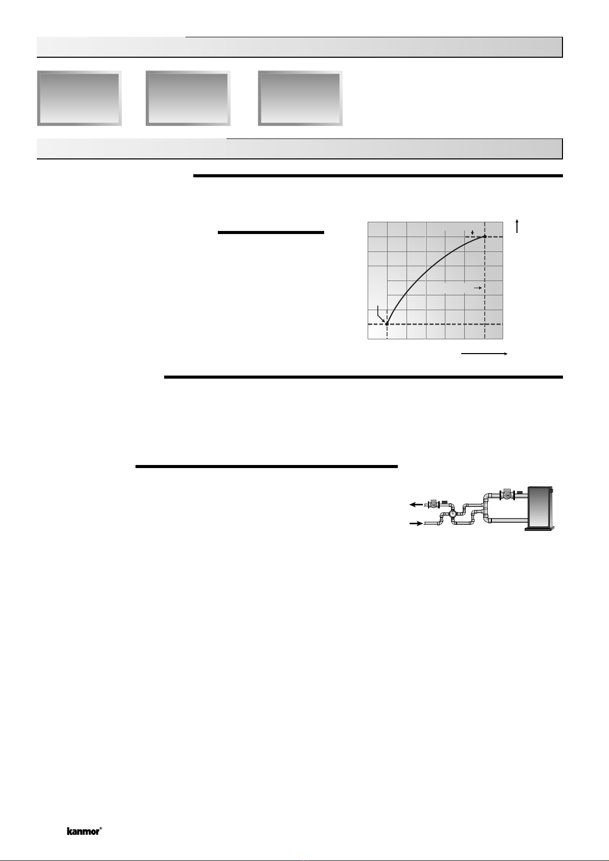
BOILER TARGET TEMPERATURE (Boil TRG)
The Boiler Target temperature is determined by the operation of the mixing de ice. The control uses a method called Boiler
Load Reset in order to determine the required boiler supply water temperature. The control operates the boiler at a supply
temperature that is sufficient to satisfy the requirements of the mixing de ice. If the boiler supply water temperature is not
sufficient, the control increases the boiler target temperature. If the boiler supply water temperature is more than sufficient, the
control decreases the boiler target temperature. If the control does not ha e a requirement for heat from the boiler, it does not
show a boiler target temperature. Instead, “– – –” is displayed in the LCD.
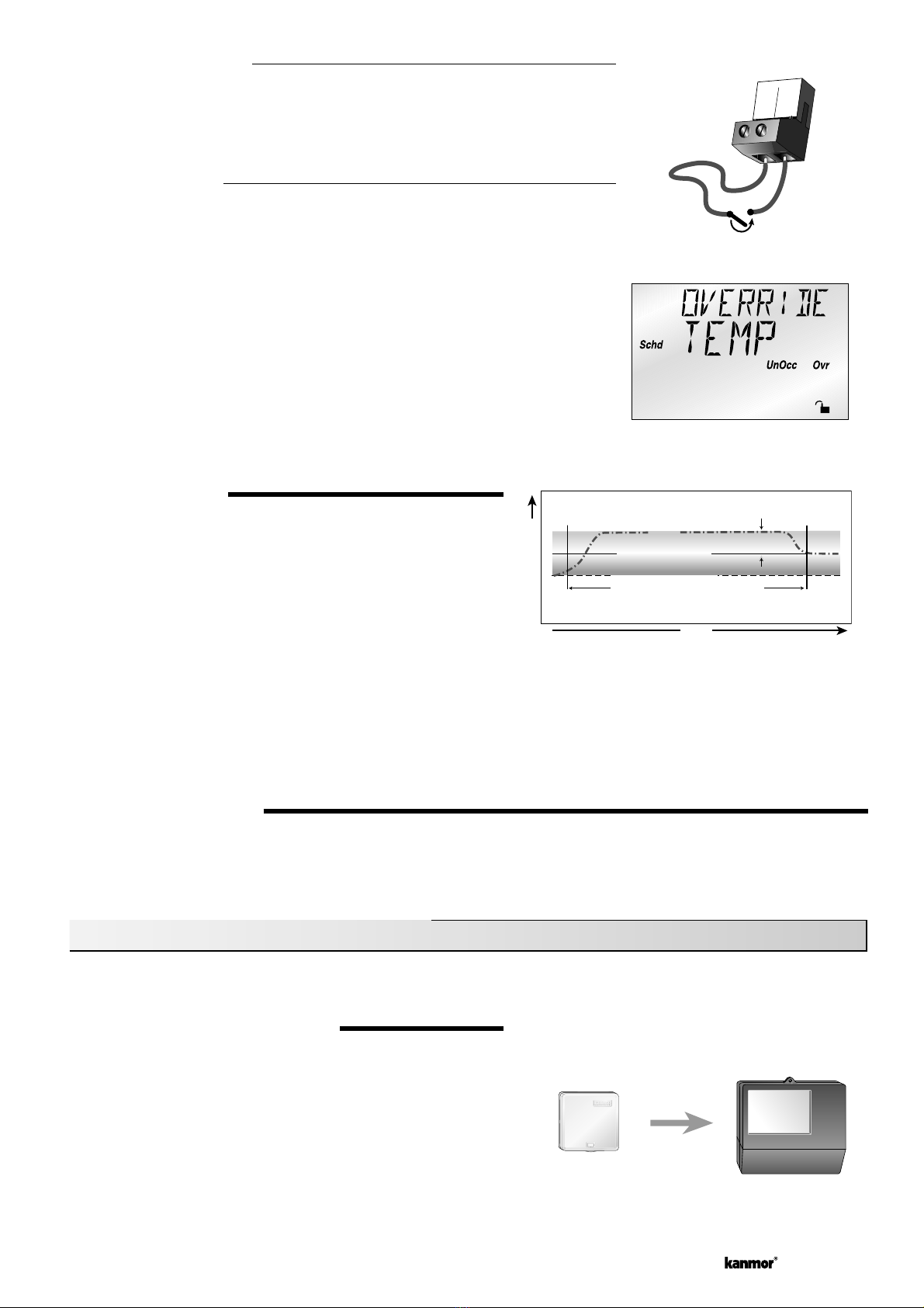
BOILER DIFFERENTIAL (Boil DIFF)
An on / off heat source such as a boiler must be operated with a differential to pre ent short cycling. This differential is centered
around the Boil TRG temperature. If the boiler supply temperature drops ½ of the differential below the Boil TRG temperature,
the control closes the boiler contact to fire the boiler. If the boiler supply temperature rises ½ of the differential abo e the
Boil TRG temperature, the control opens the boiler contact to turn off the boiler. With the control, either a fixed or automatic
differential setting is selected. If the AUTO differential is selected, the control automatically adjusts the boiler differential setting
under the current load conditions to a oid short cycling.
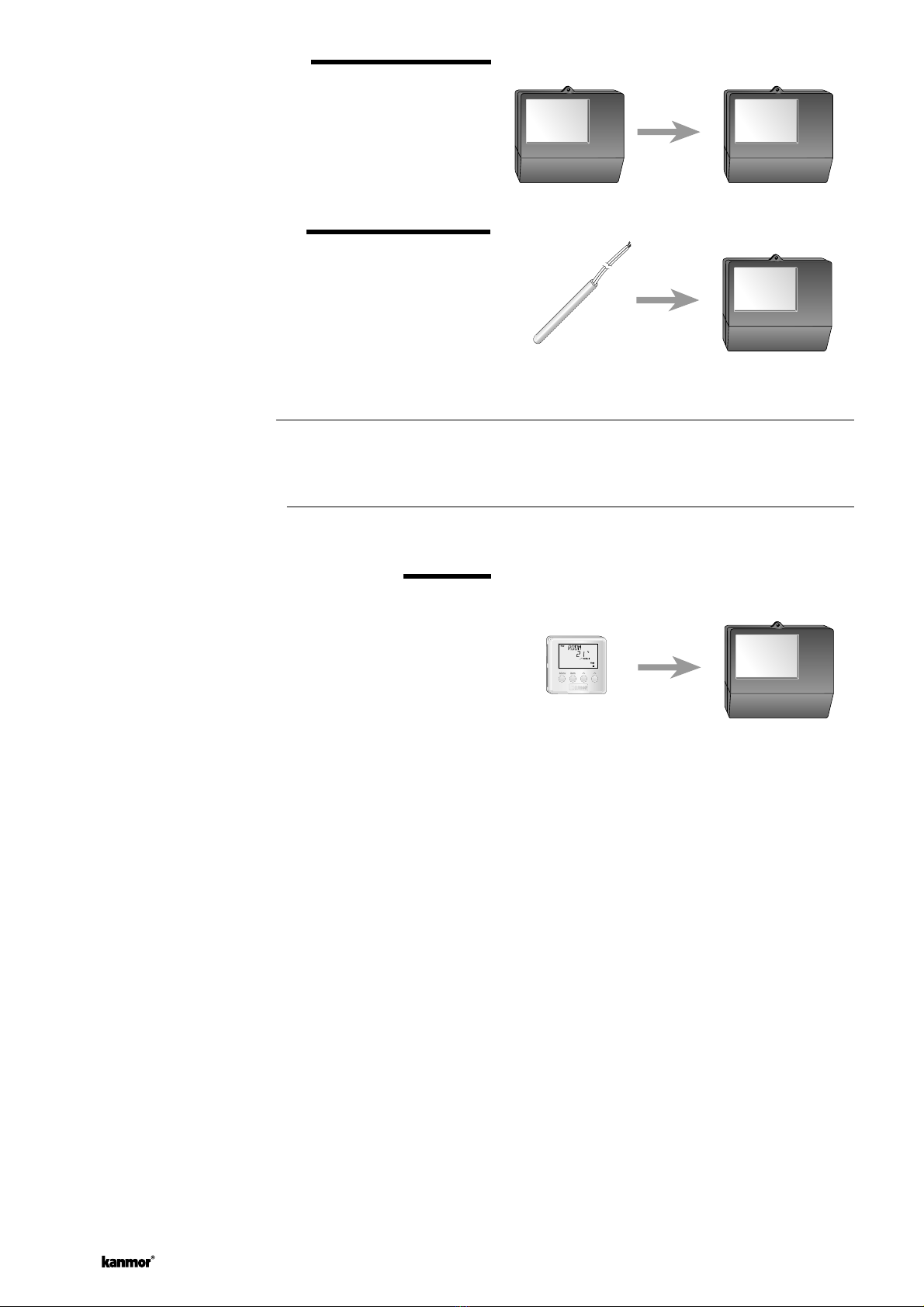
BOILER MINIMUM (Boil MIN)
The Boil MIN is the lowest water temperature that the control is
allowed to use as a Boil TRG temperature. During mild conditions, if
the control calculates a Boil TRG temperature that is below the Boil
MIN setting, the Boil TRG temperature is adjusted to at least the
Boil MIN setting. During this condition, if the boiler is operating, the
Minimum pointer turns on in the LCD while the Boil TRG or the Boil
SUP temperature is iewed. If the installed boiler is designed for
condensing operation, set the Boil MIN adjustment to OFF.
BOILER MAXIMUM (Boil MAX)
The Boil MAX is the highest water temperature that the control
is allowed to use as a Boil TRG temperature. If the control does
target Boil MAX, and the Boil SUP temperature is near the Boil MAX
temperature, the Maximum pointer turns on in the LCD while the
Boil TRG or the Boil SUP temperature is iewed. At no time does the
control operate the boiler abo e 248°F (120°C).
BOILER PROTECTION (Boil MIN)
The control is capable of pro iding boiler protection from cold mixing system return water temperatures. If the boiler sensor
temperature is cooler than the Boil MIN setting while the boiler is firing, the control reduces the output from the mixing de ice.
This limits the amount of cool return water to the boiler and allows the boiler temperature to reco er. This feature can only be
used if the Boil SENS item is not set to NONE.
BOILER OPERATION
When the control determines that boiler operation is required, the Boiler contact terminals (6 and 7) close. While the boiler
contact is closed, the burner segment in the LCD is displayed.

© 2003 D 362e - 06/03 10 of 32
BOILER FIRE DELAY (Boil DLY)
The Boil DLY is the delay time that may happen between the time that the control closes the boiler contact and the burner fires.
This delay is usually the result of a burner pre-purge or other forms of time delay built into the burner’s safety circuits.
BOILER MASS (Boil MASS)
The Boil MASS setting allows the control to adjust to different types of heat sources depending on their thermal mass.
Light (LITE)
The LITE setting is selected if the boiler that is being used has a low thermal mass. This means that the boiler has a ery
small water content and has ery little metal in the heat exchanger. A boiler that has a low thermal mass comes up to
temperature quite rapidly. This is typical of many copper fin-tube boilers.
Medium (MED)
The MED setting is selected if the boiler that is being used has a medium thermal mass. This means that the boiler either
has a large water content and a low metal content or a low water content and a high metal content. This is typical of many
modern residential cast iron boilers.
Heavy (HEVY)
The HEVY setting is selected if the boiler that is being used has a high thermal mass. This means that the boiler has both
a large water content and a large metal content. A boiler that has a high thermal mass is relati ely slow in coming up to
temperature. This is typical of many commercial cast iron and steel tube boilers.
Section C2: Boiler Return Sen or
BOILER SENSOR ON THE RETURN (Boil SENS = RET)
The boiler sensor should be located on the boiler return if the 362e is one of many
controls that can call for boiler operation. When in the return mode, the control
pro ides a boiler enable. The control no longer tries to control the boiler supply water
temperature directly but allows the boiler to operate at its operating aquastat setting. If
this mode of operation is selected, the boiler pump should either operate continuously
or be operated in parallel with the Mixing Pump. The boiler pump should not be
operated by the boiler’s aquastat as this may lead to improper cycling of the boiler
because of inconsistent flow past the boiler return sensor.
When the mixing de ice begins to ramp up, the boiler contact on the control closes. The boiler contact remains closed until the
mixing de ice no longer requires heat. With the sensor on the boiler return, the control is still capable of pro iding boiler return
protection as described in section A.
Section C3: No Boiler Sen or
NO BOILER SENSOR (Boil SENS = NONE)
The control is capable of operating without a boiler sensor if desired. Without a boiler
sensor, the control is unable to pro ide boiler return protection. The boiler contact
still functions without the boiler sensor. When the mixing de ice begins to ramp up,
the boiler contact on the control closes. The boiler contact remains closed until the
mixing de ice no longer requires heat. This type of application is typical if the control
is drawing heat from a heat source that already incorporates some form of boiler
return protection.

11 of 32 © 2003 D 362e - 06/03
AUTION
Improper installation and operation of this control could result in damage to the equipment and possibly e en personal injury.
It is your responsibility to ensure that this control is safely installed to all applicable codes and standards. This electronic
control is not intended for use as a primary limit control. Other controls that are intended and certified as safety limits must
be placed into the control circuit. Do not open the control. Refer to qualified personnel for ser icing. Opening oids warranty
and can result in damage to the equipment and possibly e en personal injury.
STEP ONE GETTING READY
Check the contents of this package. If any of the contents listed are missing or damaged, please contact your wholesaler or
kanmor sales representati e for assistance.
Type 362e includes: One Mixing Control 362e, One Outdoor Sensor 070e, Two Uni ersal Sensors 071e
Data Brochures D 362e, D 070e, User Brochure U 362e, Essay E 007e.
Note: Carefully read the details of the Sequence of Operation to ensure that you ha e chosen the proper control for your application.
STEP TWO MOUNTING THE BASE
In tallation
Lift the front co er up and
away from the control.
Loosen the screws at the
front of the wiring co er.
The wiring co er pulls
straight out from the
wiring chamber.
Remo e the safety di iders
from the wiring chamber by
pulling them straight out of
their groo es.
Press the control release
clip on the base inside the
wiring chamber and slide
the control upwards.
The control lifts up and away
from the base.
The base is ready for
mounting. There are 10
conduit knock-outs at
the back and bottom of
the wiring chamber.
Press down at the fingertip
grips on top of the front co er
and pull out and down.
Control release clip
Control
release
clip
13 Mounting holes
The control can be mounted
on a standard DIN rail. This
will be a popular option for
those who prefer to mount
the control inside a larger
electrical panel.
The wiring can enter the
bottom or the back of the
enclosure. Knock-outs pro-
ided in the base allow the
wiring to be run in conduit
up to the enclosure. The
base also has holes that line
up with the mounting holes
of most common electrical
boxes.

© 2003 D 362e - 06/03 12 of 32
STEP THREE ROUGH-IN WIRING
All electrical wiring terminates in the control base wiring chamber. The base has standard 7/8” (22 mm) knockouts which accept
common wiring hardware and conduit fittings. Before remo ing the knockouts, check the wiring diagram and select those
sections of the chamber with common oltages. Do not allow the wiring to cross between sections as the wires will interfere
with safety di iders which should be installed at a later time.
Power mu t not be applied to any of the wire during the rough-in wiring tage.
• Multi-strand 16 AWG wire is recommended for all 230 V (ac) wiring due to its superior fl exibility and ease of installation
into the terminals.
• All wires are to be stripped to a length of 3/8” (9 mm) to ensure proper connection to the control.
• Install the Outdoor Sensor 070e, Boiler Sensor 071e, and Mixing Sensor 071e according to the instructions in Data
Brochure D 070e and run the wiring back to the control.
• If a Room Temperature Unit (RTU) 062e or 063e is used, install the RTU according to the installation instructions in Data
Brochure D 062e and run the wiring back to the control.
• If a Slab Sensor 079e is used, install the Slab Sensor according to the installation instructions in Data Brochure D 070e
and run the wiring back to the control or RTU.
• If a Remote Display Module (RDM) 040e is used, install the RDM according to the installation instructions in Data
Brochure D 040e and run the wiring back to the control.
• If a kanmor Zone Control is used, run the wires from the Zone Control to the 362e. Refer to the instructions supplied
with the Zone Control.
• Run wire from other system components (pumps, boiler, actuator motors, etc.) to the control.
• Run wires from the 230 V (ac) power to the control. Use a clean power source with a minimum 15 A circuit to ensure
proper operation.
STEP FOUR ELECTRICAL CONNECTIONS TO THE CONTROL
The installer should test to confirm that no oltage is present at any of the wires. Push the control into the base and slide it down
until it snaps firmly into place.
Powered Input onnections
230 V (ac) Power
Connect the 230 V (ac) power supply to the Power N and Power L terminals
(3 and 4). This connection pro ides power to the microprocessor and display of
the control. As well, this connection pro ides power to the Mix Pmp terminal (5)
from the Power L terminal (4).
Mixing Demand
To generate a Mixing Demand, a oltage between 24 V (ac) and 230 V (ac) must
be applied across the Mix Demand terminals (1 and 2).
Output onnections
Mixing Pump Contact (Mix Pmp)
The Mix Pmp output terminal (5) on the control is a powered output. When the
relay in the control closes, 230 V (ac) is pro ided to the Mix Pmp terminal (5) from
the Power L terminal (4). To operate the mixing pump, connect one side of the
mixing pump circuit to terminal 5 and the second side of the pump circuit to the
neutral (N) side of the 230 V (ac) power supply.
Boiler Contact
The boiler terminals (6 and 7) are an isolated output in the control. There is no
power a ailable on these terminals from the control. These terminals are to be
used as a switch to either make or break the boiler circuit. When the control
requires the boiler to fire, it closes the contact between terminals 6 and 7.
3
Power
4
230 V (ac)
NL
1
Mix
Demand
2
24 to 230 V (ac)
5
Mix
Pmp
NL
3
Power
230 V (ac)
N
L
4
6
Boiler
7

13 of 32 © 2003 D 362e - 06/03
Mixing Valve Actuator
Connect one side of the power supply for the actuator to the Pwr
Mix terminal (8) on the 362e. The output relay Opn (9) is then
connected to the open terminal of the actuating motor and the
output relay Cls (10) is connected to the close terminal of the
actuating motor. Connect the second side of the power supply
for the actuator to the common terminal of the actuating motor.
Sensor and Unpowered Input onnections
Do not apply power to these terminals as this will damage the
control.
Outdoor Sen or
Connect the two wires from the Outdoor Sensor 070e to the
Com and Out terminals (15 and 18). The Outdoor Sensor is
used by the control to measure the outdoor air temperature.
Boiler Sen or
Connect the two wires from the Boiler Sensor 071e to the Com
and Boil terminals (15 and 17). The Boiler Sensor is used by the
control to measure the water temperature of the boiler.
Mixing Sen or
Connect the two wires from the Mixing Sensor 071e to the
Com and Mix terminals (15 and 16). The Mixing Sensor is used
by the control to measure the supply water temperature after
the mixing de ice. Normally the sensor is attached to the pipe
downstream of the mixing pump.
10K Sen or
Either an Indoor Sensor, Floor (slab) Sensor, or Zone Control
can be connected to the 10K input. If a sensor is used, connect
the two wires from the sensor to the Com and 10K terminals
(12 and 13).
Zone Control Input
If an external kanmor Zone Control is used, connect the wire
from the Com Sen terminal on the Zone Control to the Com
terminal (12) on the 362e. Connect the Zo Out terminal on the
Zone Control to the 10K terminal (13) on the 362e.
Note: The wires from the Zone Control are polarity sensiti e.
The communication does not operate correctly if the wires are
re ersed.
tN1/tN2 Device
A Room Temperature Unit (RTU) 062e or 063e, or a Remote
Display Module (RDM) 040e can be connected to the tN1/tN2
input. Connect the Com terminal from the appropriate de ice
to the Com terminal (12) on the control. Connect the tN1 or tN2
terminal from the appropriate de ice to the tN1/tN2 terminal (11)
on the control.
Note: The wires from the RTU and the RDM are polarity
sensiti e. The tN1/tN2 de ice does not operate correctly if the
wires are re ersed.
8
Pwr
Mix
9
Opn
10
Cls
24 to 230 V (ac)
L
N
16
Mix
17
Boil
18
Out
15
Com
16
Mix
17
Boil
18
Out
15
Com
Boiler
Sensor
or
15
Com
16
Mix
Mixing
Sensor
13
10K
12
Com
Com
Zo
Out
12 13
Com 10K
Zone Control362e
11
tN1/
tN2
12
Com
13
10K

© 2003 D 362e - 06/03 14 of 32
UnOccupied Switch
If an external timer or switch is used, connect the two wires from the external
switch to the Com and UnO Sw terminals (12 and 14). When these two terminals
are shorted together, the control registers an UnOccupied signal.
Note: The setback o erride in the schedule menu of the control o errides any
external signal that is present on the UnOccupied Switch terminals.
STEP FIVE TESTING THE WIRING
Each terminal block must be unplugged from its header on the control before power is applied for testing. To remo e the
terminal block, pull straight down from the control.
The following tests are to be performed using standard testing practices and procedures and should only be carried out by
properly trained and experienced persons.
A good quality electrical test meter, capable of reading from at least 0 - 300 V (ac) and at least 0 - 2,000,000 Ohms, is essential
to properly test the wiring and sensors.
Test The Sensors
In order to test the sensors, the actual temperature at each sensor
location must be measured. A good quality digital thermometer
with a surface temperature probe is recommended for ease of
use and accuracy. Where a digital thermometer is not a ailable,
a spare sensor can be strapped alongside the one to be tested
and the readings compared. Test the sensors according to the
instructions in Data Brochure D 070e.
Test The Power Supply
Make sure exposed wires and bare terminals are not in contact
with other wires or grounded surfaces. Turn on the power and
measure the oltage between the N and L terminals (3 and 4)
using an AC oltmeter, the reading should be between 207 and
253V (ac).
Test The Powered Inputs
Mixing Demand
If a mixing demand is used, measure the oltage between the
Mix Demand terminals (1 and 2). When the mixing demand
de ice calls for heat, you should measure between 20 and
260 V (ac) at the terminals. When the mixing demand de ice is
off, you should measure less than 5 V (ac).
Testing The Outputs
Mixing Pump (Mix Pmp)
If a mixing pump is connected to the terminal (5), make sure
that power to the terminal block is off and install a jumper
between the Power L and the Mix Pmp terminals (4 and 5).
When power is applied to the Power N and Power L terminals (3
and 4), the mixing pump should start. If the pump does not turn
on, check the wiring between the terminal block and pump and
refer to any installation or troubleshooting information supplied
with the pump. If the pump operates properly, disconnect the
power and remo e the jumper.
13
10K
14
UnO
Sw
12
Com
Timer Switch
16 17 18
Mix Boil Out
15
Com
4
L
Power
3
N
V
207 to 253 V (ac)
2
Mix
Demand
1
V
20 to 260 V (ac)
L
Power
5
Mix
Pmp
3
N
230 V (ac)
L
N
4

15 of 32 © 2003 D 362e - 06/03
Boiler
If the boiler is connected to the Boiler terminals (6 and 7), make sure power to the boiler circuit is off and install a jumper
between the terminals. When the boiler circuit is powered up, the boiler should fire. If the boiler does not turn on, refer to
any installation or troubleshooting information supplied with the boiler. (The boiler may ha e a flow switch that pre ents
firing until the boiler pump is running.) If the boiler operates properly, disconnect the power and remo e the jumper.
Mixing Valve Actuator
If a floating action actuating motor circuit is connected to the Pwr Mix, Opn, and Cls terminals (8, 9, and 10), make sure
power to the motor circuit is off and install a jumper between the Pwr Mix and Opn terminals (8 and 9). When the circuit is
powered up, the actuator should mo e in the opening direction. If it does not, check the wiring between the terminals and
the actuating motor. Refer to any installation or troubleshooting information supplied with the motor. If the motor closes
instead of opening, the wiring of the actuating motor must be re ersed. If the al e opens correctly, turn off the power to
the circuit and remo e the jumper. Install a jumper between the Pwr Mix and Cls terminals (8 and 10). When the circuit
is powered up, the al e should mo e in the closing direction. If it does not, check the wiring between the terminals and
the actuating motor. Refer to any installation or troubleshooting information supplied with the motor. If the motor closes
correctly, turn off the power to the circuit and remo e the jumper.
onnecting The ontrol
Make ure all power to the device and terminal block i off and remove any
remaining jumper from the terminal .
Reconnect the terminal blocks to the control by carefully aligning them with their
respecti e headers on the control and then pushing the terminal blocks into the
headers. The terminal blocks should snap fi rmly into place.
Install the supplied safety di iders between the unpowered sensor inputs and the
powered wiring chambers.
Apply power to the control. The operation of the control on power up is described in
the Sequence of Operation section of this brochure.
8
79
610
Pwr
Mix
Opn Cls
Boiler
Cleaning
The Control’s exterior can be cleaned using a damp cloth. Moisten cloth with water and wring out prior to wiping control. Do not
use sol ents or cleaning solutions.

© 2003 D 362e - 06/03 16 of 32
DIP Switch Setting
The DIP Switch settings on the control are ery important and should be set to the
appropriate settings prior to making any adjustments to the control through the User
Interface. The DIP switch settings change the items that are a ailable to be iewed
and / or adjusted in the User Interface.
If the setback / None DIP switch is changed while the control is powered up, the control
responds to the change in setting by returning the display to the View Menu.
LOCK / UNLOCK (FACTORY SETTING IS UNLOCK)
The Lock / Unlock DIP switch is used to lock and unlock the access le el of the control and tN1/tN2 de ice. To determine if the
control is currently locked or unlocked, a small segment representing a padlock is iewed in the bottom right hand corner of the
display. When the padlock is closed, the access le el cannot be changed.
To change the access le el, set the DIP switch to the Unlocked, or down position. The current access le el of the control or
tN1/tN2 de ice is iewed in its Miscellaneous (Misc) Menu. While iewing the access le el, use the ▲ and ▼ keys to select
between the Limited (LTD), User (USER), Installer (INST), or Ad anced (ADV) access le els.
To lock the access le el, select the appropriate access le el in the Miscellaneous (Misc) Menu and mo e the DIP switch from
the unlocked position to the locked position. As long as the DIP switch is in the locked position, the access le el of the control or
tN1/tN2 de ice can no longer be iewed or adjusted in its Miscellaneous (Misc) Menu.
SETBACK / NONE (FACTORY SETTING IS NONE)
The Setback / None DIP switch enables and disables the setback functions of the control. When the DIP switch is set to the None or
down position, the control ignores any external setback signal, and its user interface does not display the UnOccupied adjustments.
When the DIP switch is set to the Setback position, the setback features in the control are enabled. The control responds to an
external setback signal generated on the UnO Sw terminal.
Setbac
k
None
Acce Level
The kanmor Mixing Control 362e comes with four Access Le el set-
tings. These Access Le els restrict the number of Menus, Items,
and Adjustments that can be accessed by the user. The four ac-
cess le els are Limited (LTD), User (USER), Installer (INST) and
Ad anced (ADV).
The access le el of the control is found in the Miscellaneous (Misc)
Menu when the Lock / Unlock DIP switch is set to the Unlocked
position. In the Ad anced access le el, all of the control settings
are a ailable to the user. In the User access le el, only a few of the
menus and items are a ailable. The Limited access le el is the most
restricted of them all. The control’s factory setting is Installer (INST).
This access le el is suffi cient for the normal set up of the control.
Once the control is set up, the appropriate access le el should be
selected for the people that deal with the control on a regular basis.

17 of 32 © 2003 D 362e - 06/03
View Menu (1 of 1)
-67 to 149°F
(-55 to 65°C)
Item Field
Acce
Level De cription Range
Section
LTD
USER
INST
ADV
B2
B2
B2
B2
B1
B1
C1
C1
C2
Current outdoor air temperature as measured by the
outdoor sensor. This is the default display for the control.
Target room air temperature “– – –” denotes no heat is
required.
10K = INDR
Measured room air temperature at the indoor sensor.
10K = INDR
This is the signal that is being recei ed from a kanmor
Zone Control.
10K = ZoIn
Current floor (slab) sensor temperature.
10K = FLOR
MIX MIN = OFF
Target mixed supply is the temperature the control is
currently trying to maintain at the mixing sensor.
Current mixed supply water temperature as measured by
the mixing sensor.
Target boiler supply is the temperature the control is
currently trying to maintain at the boiler sensor + / - ½ of
the differential.
BOIL SENS = SUP
Current boiler supply water temperature as measured by
the boiler sensor.
BOIL SENS = SUP
Current boiler return water temperature as measured by
the boiler sensor.
BOIL SENS = RET
– – –, 35 to 100°F
(– – –, 2 to 38°C)
-58 to 167°F
(-50 to 75°C)
– – –, 35 to 110°F
(– – –, 2 to 43°C)
-58 to 167°F
(-50 to 75°C)
– – –, -25 to 248°F
(– – –, -32 to 120°C)
-31 to 266°F
(-35 to 130°C)
-31 to 266°F
(-35 to 130°C)
– – –, -31 to 266°F
(– – –, -35 to 130°C)
-31 to 266°F
(-35 to 130°C)
Note: = The Item is set to, ≠ The Item is not set to

© 2003 D 362e - 06/03 18 of 32
Adju t Menu (1 of 2)
B1
UnOc
c
B2
B2
B1
B1
B1
B1
B1
B1
The desired room air temperature during an
UnOccupied period.
Dip witch = Setback
No RTU connected
The de ice that is to be connected to the 10K
input terminal.
No RTU connected
The minimum temperature at the floor (slab)
sensor as long as the control is not in WWSD.
10K = FLOR
MIX MIN = OFF
No RTU connected
The maximum temperature at the floor (slab)
sensor.
10K = FLOR
MIX MIN = OFF
No RTU connected
The design indoor air temperature used in the
heat loss calculations for the heating system.
The design supply water temperature used in the
heat loss calculations for the heating system.
The design outdoor air temperature used in the
heat loss calculations for the heating system.
The minimum supply water temperature for the
mixing system.
NONE, INDR,
ZoIn, FLOR, (only)
if MIX MIN = OF
F
Default = NONE
OFF, 35 to 120°F
(OFF, 2 to 49°C)
Default = 70°F
(21°C)
40 to 150°F
(4 to 66°C)
Default = 90°F
(32°C)
OFF, 0:20 to 8:00 Hr
Default = OFF
U/F1 (Screeded),
U/F2 (Plated), UNIT,
FIN, RAD(iator),
BASE(board)
Default = U/F1
70 to 220°F
(21 to 104°C)
Default = 120°F
(49°C)
The amount of morning boost.
Dip witch = Setback
No RTU connected
10K ≠ ZoIn
The type of terminal units that are being used in
the heating system.
35 to 100°F
(2 to 38°C)
Default = 70°F
(21°C)
B2
Oc
c
The desired room air temperature during an
Occupied period.
Note: There is only a ±3°F (±1°C) adjustment in
the LTD access le el.
No RTU connected
-60 to 32°F
(-51 to 0°C)
Default = 10°F
(-12°C)
B1
35 to 100°F
(2 to 38°C)
Default = 70°F
(21°C)
35 to 100°F
(2 to 38°C)
Default = 65°F
(18°C)
OFF, 35 to 150°F
(OFF, 2 to 66°C)
Default = OFF)
The maximum supply water temperature for the
mixing system.
B1
80 to 212°F
(27 to 99°C)
Default = 140°F
(60°C)
Item Field
Acce
Level De cription Range
Section
LTD
USER
INST
ADV
Actual
Setting
Note: = The Item is set to, ≠ The Item is not set to

19 of 32 © 2003 D 362e - 06/03
Item Field
Acce
Level De cription Range
Section
LTD
USER
INST
ADV
C1
C1 The differential that the control is to use when it is
operating the boiler.
Boil SENS = SUP
The location of the boiler sensor. This affects
operation of the boiler contact.
LITE, MED,
HEVY
Default = MED
The thermal mass characteristics of the boiler
that is being used.
Boil SENS = SUP
SUP (Supply)
RET (Return)
NONE
Default = SUP
The time that the actuating motor requires to
operate from fully closed to fully open. 30 to 230 sec
Default = 150 sec
Adju t Menu (2 of 2)
AUTO, 2 to 42°F
(AUTO, 1 to 23°C)
Default = AUTO
C2
C1
C3
C1 The maximum temperature allowed for the boiler
target temperature.
Boil SENS = SUP
120 to 225°F, OFF
(49 to 107°C, OFF)
Default = 210°F
(99°C)
The minimum temperature allowed for the boiler
target temperature.
Boil SENS ≠ NONE
OFF, 80 to 180°F
(OFF, 27 to 82°C)
Default = 140°F
(60°C)
C1
The time delay the control can expect between the
time the boiler contact closes and the burner fires.
Boil SENS = SUP
C1 0:00 to 3:00 min
(1 sec. increments)
Default = 0:10 min
Oc
c
35 to 100°F, OFF
(2 to 38°C, OFF)
Default = 70°F
(21°C)
The system’s warm weather shut down during the
Occupied period.
B1
UnOc
c
The system’s warm weather shut down during the
UnOccupied period.
Dip witch = Setback
B1
35 to 100°F, OFF
(2 to 38°C, OFF)
Default = 60°F
(16°C)
B1 The maximum length of time that the boiler pump
will continue to operate after the mixing demand
has been remo ed.
OFF,
0:10 to 40:00 min
Default = 0:20
min
Enables or disables the Soft Start feature in the
control. NONE, MIX
Default = NONE
B1
AThe frequency with which the control will
exercise the pumps and ales that are
operated by the control.
30 to 240 hr,
OFF
Default = 70 hr
Actual
Setting
Note: = The Item is set to, ≠ The Item is not set to

© 2003 D 362e - 06/03 20 of 32
Item Field
Acce
Level De cription Range
Section
LTD
USER
INST
ADV
The type of setback o erride that is in effect for the
heating system.
DIP witch = Setback
HOL i available even if DIP ≠ Setback
NONE, TMPY Occ
Ovr, PERM Occ Ovr,
TEMP UnOcc Ovr,
PERM UnOcc Ovr,
HOL Ovr
Default = NONE
Schd (Schedule) Menu (1 of 1)
B1
°F, °C
Default = °C
Item Field De cription Range
Acce
Level
LTD
USER
INST
ADV
The units of measure that all of the temperatures are to be
displayed in by the control.
Mi c (Miscellaneous) Menu (1 of 1)
The operating mode for the back lighting on the LCD as well
as the time of keypad inacti ity until the control automatically
returns to the default display.
BACKLITE = OFF (return after 10 econd )
BACKLITE = 30 ec (return after 30 econd )
BACKLITE = ON (return after 90 econd )
OFF, 30 sec, ON
Default = ON
The access le el that is to be used by the control.
DIP witch = Unlock
ADV, INST, USER,
LTD
Default = INST
Room Temperature Unit (RTUs) 062e and 063e
A single RTU may be connected to the Mixing Control 362e in order to pro ide the control with
indoor temperature feedback for the mixing side of the heating system. When using an RTU, se eral
items related to the mixing side of the heating system are no longer a ailable in the control’s User
Interface. These items are a ailable only in the RTU’s User Interface. Also, the number of items that
are a ailable on the RTU depends on the type of RTU that is connected to the control.
– – –, 14 to 167°F
(– – –, -10 to 75°C)
B2
Item Field
Acce
Level De cription Range
Section
LTD
USER
INST
ADV
RTU 062e
RTU 063e
Current room air temperature.
RTU SENS = AIR
RTU View Menu (1 of 2)
B2 Target room air temperature.
RTU SENS = AIR – – –, 35 to 100°F
(– – –, 2 to 38°C)
Note: = The Item is set to, ≠ The Item is not set to
Table of contents
Popular Control Unit manuals by other brands

Pickering
Pickering 40-519A user manual

Sony
Sony HXCU-FB80 4K/HD operating instructions

Rockford Fosgate
Rockford Fosgate iPod Interface Module Installation & operation

New Focus
New Focus 6209 user guide

schmersal
schmersal SRB 401LC operating instructions

CRE Technology
CRE Technology UNIGEN Plus Technical documentation