KARL DEUTSCH ECHOMETER 1077.080-A User manual

Operating instructions ECHOMETER 1077.080-A Ho Art. no. 7412.077-A Oil
1
EM1077-A-BA-Oil-Level-2020-04-21_EN.docx Ho/SL
2020-04-27
Operating instructions for the ultrasonic transmission
oil level meter
ECHOMETER 1077.080
-A
Rev. 1.0
© Copyright KARL DEUTSCH Prüf- und Messgerätebau GmbH + Co KG
Otto-Hausmann-Ring 101
42115 Wuppertal
Author: Ho
All rights, including those of the translation, are reserved.
No part of the documentation may be reproduced in any form (print, photocopy, microfilm or
any other method) or processed, copied or distributed using electronic systems without the
permission of KARL DEUTSCH Prüf- und Messgerätebau GmbH + Co KG.
Subject to change without notice.

Operating instructions ECHOMETER 1077.080-A Ho Art. no. 7412.077-A Oil
2
Content Page
1About this manual............................................................................................3
2Proper use, accessories..................................................................................3
3Scope of delivery .............................................................................................3
4Conformity........................................................................................................4
5Contact to KARL DEUTSCH ............................................................................6
6Important notes (read before commissioning!).............................................7
7Instructions for use..........................................................................................7
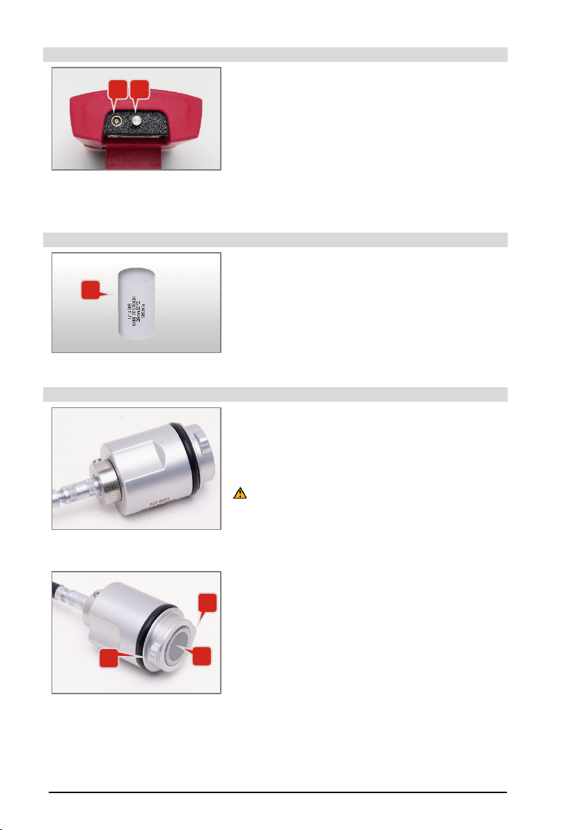
8Connections .....................................................................................................8
9Test block .........................................................................................................8
10 Probe.................................................................................................................8
11 Operation ..........................................................................................................9
11.1 Keypad with signal LED ..........................................................................9
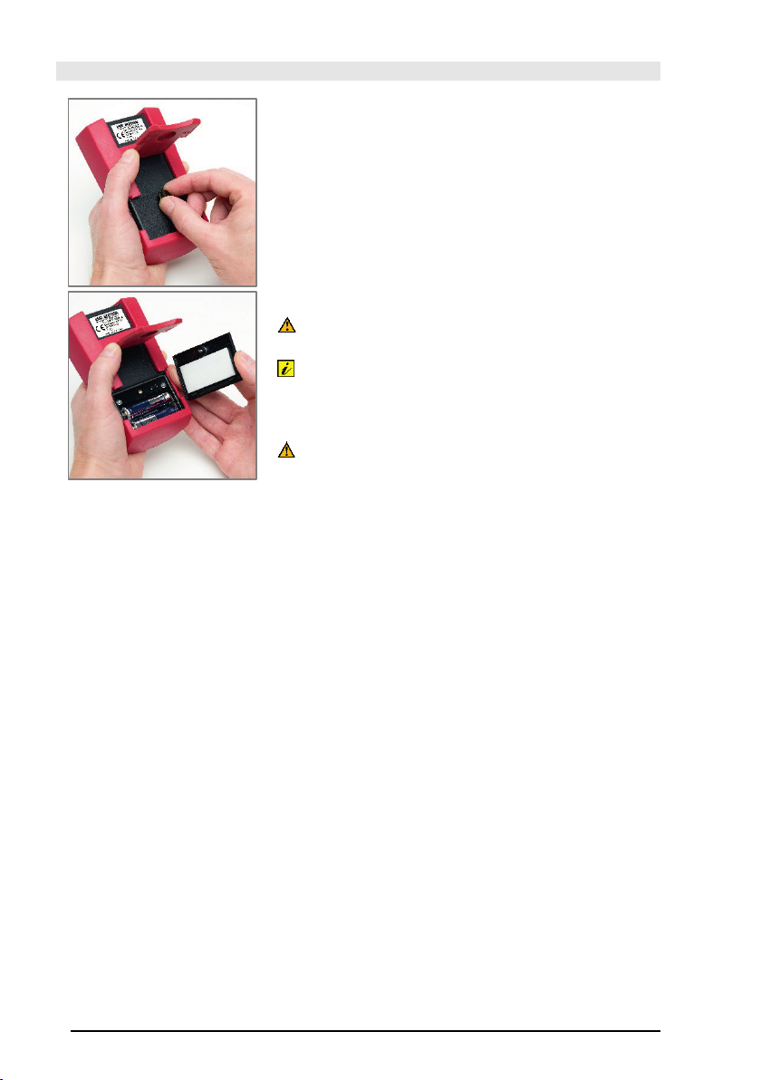
11.2 Insert battery, replace battery ..............................................................10
11.3 Connecting the probe and attaching it to the transmission oil
sump .......................................................................................................11
11.4 Measuring mode ....................................................................................13
11.4.1 Activating and deactivating........................................................13
11.4.2 Starting measurements..............................................................13
11.4.3 Performing measurements ........................................................14
11.4.4 Ending measurements...............................................................14
11.4.5 Regular control measurements..................................................15
12 Menu structure ...............................................................................................16
13 Operating menu..............................................................................................17
13.1 Device options .......................................................................................17
13.1.1 Wireless.....................................................................................17
13.1.2 Brightness..................................................................................18
13.1.3 Backlight off...............................................................................18
13.1.4 Language...................................................................................18
13.1.5 Auto Off .....................................................................................18
13.1.6 Load Factory Set. ......................................................................19
13.1.7 Info ............................................................................................19
14 Application tip, battery warning....................................................................19
15 Temperature influence...................................................................................20
16 Replacing the protective disc on the sound outlet surface........................20
17 Cleaning the device .......................................................................................21
18 Disposal ..........................................................................................................22
19 Technical data according to DIN EN 15317..................................................23
20 Software update .............................................................................................24
21 Regular check of the measuring device.......................................................24
22 Information about the built-in wireless module...........................................25
22.1 Countries with official approval ...........................................................25
22.2 United States..........................................................................................25
22.3 Canada....................................................................................................26
22.4 Japan ......................................................................................................26
22.5 Korea ......................................................................................................26
22.6 Taiwan ....................................................................................................27
22.7 China.......................................................................................................27
23Table for regular control measurements......................................................28

Operating instructions ECHOMETER 1077.080-A Ho Art. no. 7412.077-A Oil
3
1 About this manual
This operating manual is valid for the device version ECHOMETER 1077.080-A
(from the ECHOMETER complete package 1077.901-A) or W000 588 09 19 00
(part number Mercedes-Benz workshop equipment).
Instructions marked with the symbol must be read and observed to avoid any
danger to life and limb. The sections marked with the warning symbol must be
observed in order to maintain the quality of the testing process. Additional notes of
interest are marked with the info symbol .
2 Proper use, accessories
Proper use: The ECHOMETER 1077.080-A is a device for measuring
transmission oil levels in vehicles of Daimler AG. The operation of the device is
designed for technically trained personnel as commonly found in automotive
workshops. The measurement is based on the transit time of ultrasonic signals
which are sent from below through the oil in the transmission by a probe attached
to the oil sump and reflected at the oil surface. The device is intended exclusively
for use with the probe (Art. No. 1498.276) included in the scope of delivery. The
correct handling of the meter for its intended use is described in this manual. This
also means that the meter and its accessories must not be modified.
Accessories: If accessories are required for the intended use, only device-specific
KARL DEUTSCH accessories or accessories expressly approved by KARL
DEUTSCH may be used.
3 Scope of delivery
Image 1: Scope of delivery in case
(illustration without documents)
ECHOMETER 1077.080-A in protective
holster, with carrying loop in case
2 batteries, alkaline manganese, size AA
Probe cable (art. no.: 1616.023)
Probe (art. no. 1498.276)
Two spare plastic protective discs (art.
no.: 1930.010) to be glued onto the
sound outlet surface of the probe
Test block (art. no.: 1713.006) for
function control of device and probe
multilingual test book with delivery test
certificate of the device
multilingual quick guide
CD with PDF files of the manuals in
several languages

Operating instructions ECHOMETER 1077.080-A Ho Art. no. 7412.077-A Oil
4
4 Conformity

Operating instructions ECHOMETER 1077.080-A Ho Art. no. 7412.077-A Oil
5
We hereby confirm that the device/system has been developed and
manufactured in accordance with the Low Voltage Directive (2014/35/EU) and the
EMC Directive (2014/30/EU), as well as the 2011/65/EU Directive (RoHS 2) and
the EU2015/863 RoHS Directive (RoHS 3).
The following harmonized norms and standards were used for evaluation:
•EN 61000-4-2:2008; Electromagnetic compatibility (EMC) Immunity -
Electrostatic discharge immunity test
•EN 61000-4-3:2006 + A1:2007 + A2:2010; Electromagnetic compatibility
(EMC) Immunity - Radiated, radiofrequency, electromagnetic field
•EN 55011 :2016 + A1 :2017; Industrial, scientific and medical equipment -
Radio-frequency disturbance characteristics - Limits and methods of
measurement Group 1, Class B
•EN 61326-2-2:2013; Electrical equipment for measurement, control and
laboratory use - EMC requirements - Part 2-2: Particular requirements - Test
configurations, operational conditions and performance characteristics for
portable test, measurement and monitoring equipment used in low voltage
distribution systems
•EN 2-1:2013; Electrical equipment for measurement, control and laboratory
use - EMC requirements - Part 1: General requirements
•EN 61010-1:2020; Safety requirements for electrical equipment for
measurement, control, and laboratory use; Part 1: General requirements

Operating instructions ECHOMETER 1077.080-A Ho Art. no. 7412.077-A Oil
6
5 Contact to KARL DEUTSCH
You can reach us as follows:
Monday to Thursday
8 a.m. to 4 p.m. (CET/CEST)
Friday
8 a.m. to 2 p.m. (CET/CEST)
Telephone
(+49 202) 7192
-0
Fax
(+49 202) 714932
E
-Mail (general)
info@karldeutsch.de
E
-
mail (for service cases, e.g. repair,
periodic inspection, calibration,
check)
service@karldeutsch.de
Website
www.karldeutsch.de
Postal address
KARL DEUTSCH
Prüf
- und Messgerätebau
GmbH + Co KG
Postfach 132354
42050 Wuppertal,
Germany
Shipping address for devices
KARL DEUTSCH
Prüf
- und Messgerätebau GmbH + Co KG
Service
Otto
-Hausmann-Ring 101
42115 Wuppertal
Germany
Company address
Otto
-Hausmann-Ring 101
42115 Wuppertal
Germany

Operating instructions ECHOMETER 1077.080-A Ho Art. no. 7412.077-A Oil
7
6 Important notes (read before commissioning!)
Danger! Do not operate in an explosive environment: The device must not
be operated in explosive environments. Observe the safety regulations that
apply to you.
Regularly check display accuracy: In order to prevent influences on the
measurement result that cannot be detected in any other way, the display
accuracy should be checked before starting measurements (and from time to
time during longer measurements) using the test block (art. no. 1713.006)
included in the delivery. The proper function of the test system can be tested
by means of regular control measurements.
Protective disc: A thin plastic disc is glued to the sound outlet side of the
probe, which protects the sound outlet surface and ensures that the probe fits
well in the bayonet mount on the gearbox. Before inserting the probe into the
bayonet mount, ensure that the adhesive is intact and the plastic disc is
undamaged.
Batteries: If the instrument is not to be operated for a long period of time,
please remove the inserted batteries to avoid any potential damage as a result
of leaking batteries.
7 Instructions for use
Coupling: The reliability and accuracy of all measurements depends, among other
things, on how well the probe is coupled to the workpiece to be measured. Follow
the instructions for attaching the probe to the gear housing (see section 11.3).
Before applying the coupling agent, remove any debris or other deposits from the
contact surfaces of the probe and the probe holder in the oil sump.
Coupling symbol: Always make sure that the coupling symbol shows a fully
attached probe (see section 11.4.3). Should the measured value fluctuate or the
coupling symbol constantly change, you should improve the coupling (unscrew the
probe from the holder, clean the contact surfaces and screw the probe with
coupling agent back in again) and confirm the measured value with comparative
measurements.
Voltage monitoring: The ECHOMETER monitors battery capacity and
automatically switches off if the supply voltage is insufficient. The settings are
retained when the instrument is switched off.

Operating instructions ECHOMETER 1077.080-A Ho Art. no. 7412.077-A Oil
8
8 Connections
Image 2: Connection socket
with eyelet for the carrying
loop
1= Probe connection socket
2= Eyelet for carrying loop
9 Test block
Image 3: Test block
1= Test block (art. no. 1713.006)
10 Probe
Image 4: Side view of the probe
with connection cable
The connection cable of the probe (art. no.:
1498.276) is plugged in at the back (left in the
picture) and can be released by simply pulling it out
(Do not pull the cable! Grasp the plug housing to pull
out the cable!).
The ring surrounding the connector socket is an
integral part of the probe unit. Do not loosen the
grub screw provided for securing!
Image 5: Probe viewed from the
sound outlet surface (gray
circular area)
On the front side with the sound outlet surface
(position 3 in Image 5, gray circular area) of the
probe there are two lugs (positions 1 and 2 in Image
5) for locking in the bayonet lock.
1 2
1
1
2
3

Operating instructions ECHOMETER 1077.080-A Ho Art. no. 7412.077-A Oil
9
11 Operation
The keys of the ECHOMETER have different functions depending on the operating
mode of the device, which are explained in the following sections:
11.1 Keypad with signal LED
ON / OFF - button
Confirmation of the input or the displayed value
Menu call
Activate selected menu item
In the further course of the text, this key is symbolized with .
The pressure point of the key is located under the character .
Switching from a submenu item to the higher-level menu item
Switching from a main menu item to the measured value display
Activating and deactivating the display illumination
(press and hold for approx. 2 s)
This button switches the menu item backlighting OFF to Always
(lighting off) or Never (lighting on).
In the further course of the text, this key is symbolized with .
The pressure point of the key is located under the letters .
If you keep the key pressed during power-on, the device will
be reset to the factory settings (see also section 13.1.6) with the
subsequent option of language selection (see section 13.1.4). If
the device was inadvertently switched to an unknown operating
language, the desired operating language can be activated.
Move the menu selection bar upward
Move the menu selection bar downward
Under the white dot to the right of the ECHOMETER lettering,
there is the signal LED (lights up when switching off and when
sending measured values).

Operating instructions ECHOMETER 1077.080-A Ho Art. no. 7412.077-A Oil
10
11.2 Insert battery, replace battery
Image 6: Opening the
battery compartment
The device is operated with two AA/IEC R6
(Mignon) size 1.5 V cells.
Proceed as follows to insert or replace
batteries:
- Loosen knurled screw on the back of the
device (Image 6, top)
- Remove the cover of the battery compartment
(Image 6 bottom).
The symbols in the battery compartment base
provide information on the correct polarity when
inserting the batteries.
Only change batteries when the device is
switched off!
Both lithium and AlMn batteries (size AA/IEC
LR6, 1.5 V) can be used. Lithium batteries have
a longer service life due to their significantly
higher capacity.
The USB socket above the battery
compartment is for service purposes only. Do
not connect a cable here. The data of the
normal test operation can be transmitted
wirelessly, see section 13.1.1.

Operating instructions ECHOMETER 1077.080-A Ho Art. no. 7412.077-A Oil
11
11.3 Connecting the probe and attaching it to the transmission oil sump
Image 7: Sensor with cable
connection
Plug the probe cable into the socket on the
back of the probe (position 1 in Image 7).
Image 8: View of the probe
with O-ring (1) and round
protective disc (2)
Ensure that a suitable O-ring (DIN3771
22X2.5 NBR70, position 1 in Image 8
) is fitted
in the guide groove.
Check that the protective disc (position 2 in
Image 8) is undamaged and centered on the
sound outlet surface of the probe.
Replace damaged protective discs (see
section 16)!
Image 9: Probe before
insertion into the
transmission oil sump
socket
Apply some coupling agent to the protective
disc (position 1 in Image 9). The protective
disc must be provided with a thin layer of
coupling agent over the entire surface.
You can find approved coupling agents in the
Mercedes-Benz repair document
AR27.00-P-0270-02EWN.
Please observe the corresponding safety data
sheets.
1
1
2
1

Operating instructions ECHOMETER 1077.080-A Ho Art. no. 7412.077-A Oil
12
Image 10: Inserting the
probe
The socket in the oil sump is equipped with a
bayonet lock. The probe is locked by a plug-
and-turn movement.
Insert the probe in the direction of the arrow
into the oil sump socket intended for
measurement.
To lock the probe in place, turn the lugs of the
probe (positions 1 and 2 in Image 5) behind
respective catches in the socket.
When inserting the probe, rotate it so that the
locking lugs are guided past the catches in the
socket and the sound outlet surface (see
Image 5) of the probe presses against the
transmission wall.
Image 11: To lock the probe,
push it in and turn it to the
right
Press the probe fully into the socket and turn
it to the right until it is in front of the locks. The
locking is then achieved by a further rotation
of about 30° so that the probes' lugs are
guided behind the locks. It may be necessary
to press the probe slightly into the socket
again.

Operating instructions ECHOMETER 1077.080-A Ho Art. no. 7412.077-A Oil
13
11.4 Measuring mode
11.4.1 Activating and deactivating
Activate by pressing . After the device ID is briefly displayed, the last active
settings are retrieved and the device switches to the measuring mode.
Deactivate by pressing and holding down . After a short and a long flash of the
signal LED, the device is deactivated. Current settings are saved for the next time
the device is switched on again.
If the device is to remain switched off for a longer period of time: Remove the
batteries to avoid potential damage to the device as a result of battery leakage.
The language selection can be called up directly after activation (see section
11.1).
11.4.2 Starting measurements
After activation, the device automatically calls up the measuring mode with the
settings that were current when it was previously deactivated:
Image
12: No measurement: Three
horizontal lines and the symbol of
the lifted
probe
Battery level indicator
empty
full
Briefly before automatic switch
-off due
to undervoltage, the empty battery
symbol starts to
flash.
No measured value available
Symbol "lifted probe": No
measurement is taken because, for
example, the probe is not inserted or
connected in the oil sump holder or the
coupling conditions are insufficient
(e.g. due to insufficient coupling
agent). T
his symbol together with the
three horizontal lines also indicates
that the measuring range has been
exceeded.
Display unit "Millimeters""

Operating instructions ECHOMETER 1077.080-A Ho Art. no. 7412.077-A Oil
14
11.4.3 Performing measurements
When a sound coupling occurs, normally after inserting the probe into the oil sump
socket, the measurement starts automatically:
Image
13: Current measured value
with coupling symbol
•
The coupling symbol changes to .
If the displayed value fluctuates
significantly, this usually means that the
coupling is insufficient.
Remedy: Unscrew probe, clean coupling
surfaces, check protective disc for
intactness (replace if necessary),
reinsert probe with new coupling agent.
•
The currently measured value is
displayed on the screen.
11.4.4 Ending measurements
When the measurement is finished, e.g. by unscrewing the probe from the holder,
the image changes:
Image
14: Last measured
value with coupling symbol.
With this pairing symbol, the
measured value is not current.
•
The coupling symbol changes to
and
thus indicates that there is no more
evaluable sound coupling.
•
The displayed measured value remains
unchanged for about 3 seconds and is
then replaced by three horizontal lines
.
Please note that a measured value
displayed with is not up to date
. The
displayed measured value originates from
the last successful measurement!

Operating instructions ECHOMETER 1077.080-A Ho Art. no. 7412.077-A Oil
15
11.4.5 Regular control measurements
The measurement quality must be checked at the beginning of a work shift or
once a day (and in the case of longer measurements also during measurement
breaks) using the supplied test block. Any devices with which a proper control
measurement cannot be carried out must be shut down and repaired before
further use.
Image
15: Measurement on the test
block as regular control measurement
•Ensure that the test block used is clean
and without any signs of damage or wear.
•
Ensure that the temperature of all
components involved in the control
measurement is within the range of 10 °C
to 30 °C (50 °F to 86 °F).
•
Switch on the device.
•
Apply a small amount of coupling agent to
the front of the test block or to the sound
outlet of the probe (position 1 in Image
15Image 15Place the probe on the test
block.
•
The device works properly if the
measurement on the test block
produces a measured value in the
range 24 mm to 26 mm (25 mm ±
1 mm).
Recommendation: The control
measurement should be performed
between 15 °C and 25 °C (temperatur
e for
environment, device, test block, coupling
agent, etc.)!
The measured value cannot be
determined with a mechanical length
gauge, e.g. a caliper gauge.
The table at the end of this manual
(section 23) can be used to record the
regular control measurements. If there is
not enough space, it is recommended to
copy an empty table page and use it for
the recordings (a PDF file of this manual
can be found in the download area of our
website www.karldeutsch.de).
To ensure seamless traceability, make
absolutely sure that the records are not
lost!
1
1

Operating instructions ECHOMETER 1077.080-A Ho Art. no. 7412.077-A Oil
16
12 Menu structure
The symbol in the following table indicates the default values after loading the
factory settings of the instrument (see section 13.1.6).
Level Menu item
1
Device options
2
Wireless
3
Off
3
On
2
Brightness
3
Normal
3
Bright
2
Backlight off
3
Always
3
15 Sec.
3
1 Min.
3
Never
2
Language
3
German
The language selection is retained here
even after the factory setting has been
loaded.
3
English
3
Español
3
Italiano
3
Nederlands
3
Svenska
3
Polski etc. (is continuously extended)
2
Auto Off
3
Never
3
5 Min.
2
Load Factory Set.
3
Factory Set. Ok? (Security query)
2
Info (display of device info: Device, S/N, SW-Ver,
memory, battery
1
Service
2
Option code
3
Entry of option code for special functions

Operating instructions ECHOMETER 1077.080-A Ho Art. no. 7412.077-A Oil
17
13 Operating menu
The character in the following sections indicates the default values after
resetting the device to factory settings (see 13.1.6).
•calls up the operating menu.
•Use the arrow keys to select the desired menu item and activate it with
the key . If necessary, you can branch to further submenus in the same
way.
•Settings are confirmed with . Use to leave the menu item without
activating it and return to the next higher menu level (see menu structure in
section 12).
There are two main menu items:
•Device options are provided to adapt the operation of the device to its use
(detailed description from section 13.1).
•Service is intended for optional extension of device features and is accessible
after entering an option code. Optional extensions are not included in this
manual and are described separately.
13.1 Device options
13.1.1 Wireless
Off Wireless communication over short distances is disabled.
On Wireless communication over short distances (WPAN, IEEE
802.15.1) with apps on appropriately equipped external devices
(workshop diagnostic system, smartphone or similar) is possible.
When the external device searches for devices to be coupled,
the oil level meter is displayed as "ECHOMETER 1077 SN:
nnnnnn" (nnnnnn stands for the production number of the oil
level meter).
The top left corner of the display shows the symbol when the "Wireless"
option is enabled.
By pressing the button , the currently displayed measurement value is sent
to external receivers.
Power consumption increases when wireless communication is enabled.

Operating instructions ECHOMETER 1077.080-A Ho Art. no. 7412.077-A Oil
18
13.1.2 Brightness
Normal Display of the display content with normal brightness.
Bright Display of the display content with increased brightness.
The power consumption increases in proportion to the intensity of the
brightness.
13.1.3 Backlight off
Always The backlight of the display is switched off.
15 Sec. The backlight of the display is switched off after 15 seconds
without key operation or measurement.
1 Min. The backlight of the display is switched off after 1 minute without
key operation or measurement.
Never The backlight remains constantly on.
Increased power consumption when the backlight is switched on reduces
battery life.
The key (longer pressing) switches this menu item between Always and
Never during the display of the measuring screen.
13.1.4 Language
Select the operating language from the options offered here.
The selection of languages offered may vary depending on the respective device.
The set language is retained after resetting to the factory setting (as described
in section 13.1.6).
If the device was inadvertently switched to an unknown operating language:
Refer to the section 11.1on calling up the language selection menu.
13.1.5 Auto Off
Specify here whether the device should switch itself off automatically if no key is
pressed or no measurement is performed for a certain period of time.
Never The device does not switch itself off automatically.
5 Min. Automatic switch off after 5 minutes without key operation or
measurement.
Canceling the automatic switch-off: Press the key while the power-off screen is
displayed.
Settings and parameters remain stored when the device is switched off.

Operating instructions ECHOMETER 1077.080-A Ho Art. no. 7412.077-A Oil
19
13.1.6 Load Factory Set.
The device can be reset to the factory settings, which are the settings that are
active at delivery.
Factory Set. OK: Confirm the security query with the key to activate the
factory settings.
The device then continues to perform measurements with the
default values of the factory settings (see section 12).
When loading the factory settings with this menu item, the selected language is
retained.
13.1.7 Info
Call up individual instrument information on your ECHOMETER.
Instrument 1077.080 O
S/N nnnnnn
SW version 1.03/5
Memory 3.95 MiB
Battery 2.7V
Device:
Item number
of the device
Serial no.
:
Individual, five
-digit serial number of the
device
SW Ver
:
Version number of the operating software /
no. of the FPGA / software variant
Memory
:
Size of the internal memory
Battery
:
Current value of the supply voltage of the
batteries used
Image 16: Information display
14 Application tip, battery warning
Tip: If you cannot understand the measured values and suspect that there is a
problem with the settings, loading the factory settings will help in many
cases. Use the menu item "Load Factory Settings" (see section 13.1.6).
Flashing symbol in the center of the display immediately after
switching on, the unit then switches off.
Reason: Battery capacity is depleted, so that measuring operation with reliable
measured values (according to the technical data) is no longer guaranteed.
Remedy: Insert fresh batteries.

Operating instructions ECHOMETER 1077.080-A Ho Art. no. 7412.077-A Oil
20
15 Temperature influence
The speed of sound of materials changes with temperature. This applies both to
the test material and to the search unit with its protective layer and/or plastic flow
path.
The temperature sensitivity of the measured values is stored in the Mercedes-
Benz diagnostic device and is compensated there.
16 Replacing the protective disc on the sound outlet surface
The sound outlet of the probe is protected by a transparent plastic disc (see Image
8, position 2).
Damaged protective discs must be replaced in order not to influence the
measurement quality.
•Two self-adhesive replacement protective discs (art. no.: 1930.010) are
included in the scope of delivery of the device.
•Completely remove the remains of a glued-on protective disc before applying a
new protective disc.
•Only use alcohol, e.g. isopropanol, to clean the sound outlet surface.
Image 17: Remove larger residues only
at an acute angle (as parallel as
possible to the sound outlet surface)
(left)
•When removing larger residues,
ensure that the angle of removal is
as acute as possible (see Image
17) in order not to damage the
sound outlet surface!
•The adhesive side of the discs is
protected with a white foil. Remove
the foil before sticking it on by
carefully separating the foil and the
adhesive surface with a sharp
object (knife, scalpel or similar)
without damaging the adhesive
surface.
•The adhesive surface which is now
exposed and unprotected must not
be soiled.
•Glue the new protective disc
centrally on the sound outlet
surface.
•Gently rub out any trapped air
bubbles with a soft cloth, applying
slight pressure from the inside to
the outside.
Table of contents
Other KARL DEUTSCH Measuring Instrument manuals