KARL DEUTSCH LEPTOSKOP 2042 User manual

L42BA1.4E Ho 16-Sep-08
Instruction Manual for the
Coating Thickness Gauge
LEPTOSKOP 2042
Rev. 1.4
This manual is part of the delivery of the
LEPTOSKOP 2042 with serial number:
© Copyright by
KARL DEUTSCH Prüf- und Messgerätebau GmbH + Co KG
Otto-Hausmann-Ring 101
42115 Wuppertal
Author: ho
All rights, incl. translation, reserved.
No part of the documentation may reproduced, processed by electronic systems, duplicated or
distributed, neither by print, copy, micro fiche or in any other manner, without the prior permis-
sion of KARL DEUTSCH Prüf- und Messgerätebau GmbH + Co KG.
Subject to change without notice.
Instruction Manual LEPTOSKOP 2042 Art. No. 7423.421 1

Instruction Manual LEPTOSKOP 2042 Art. No. 7423.421
2
Contents Page
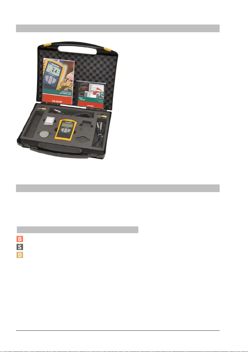
1Scope of delivery _________________________________________________________4
2About this manual ________________________________________________________4
3Application range_________________________________________________________5
4Important notes (read prior to first start-up!) __________________________________5
5Contacting KARL DEUTSCH ________________________________________________6
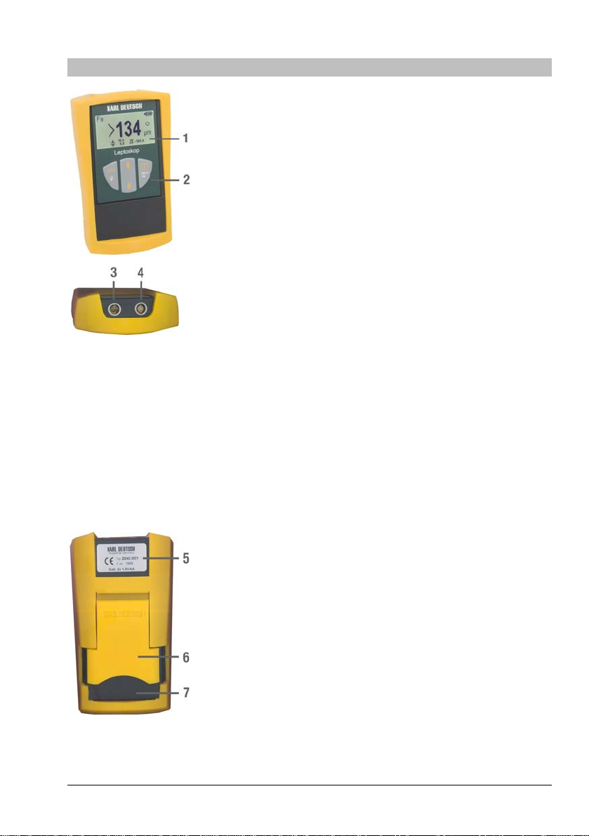
6Controls, interface and cable _______________________________________________7
7Keys and menu operation __________________________________________________8
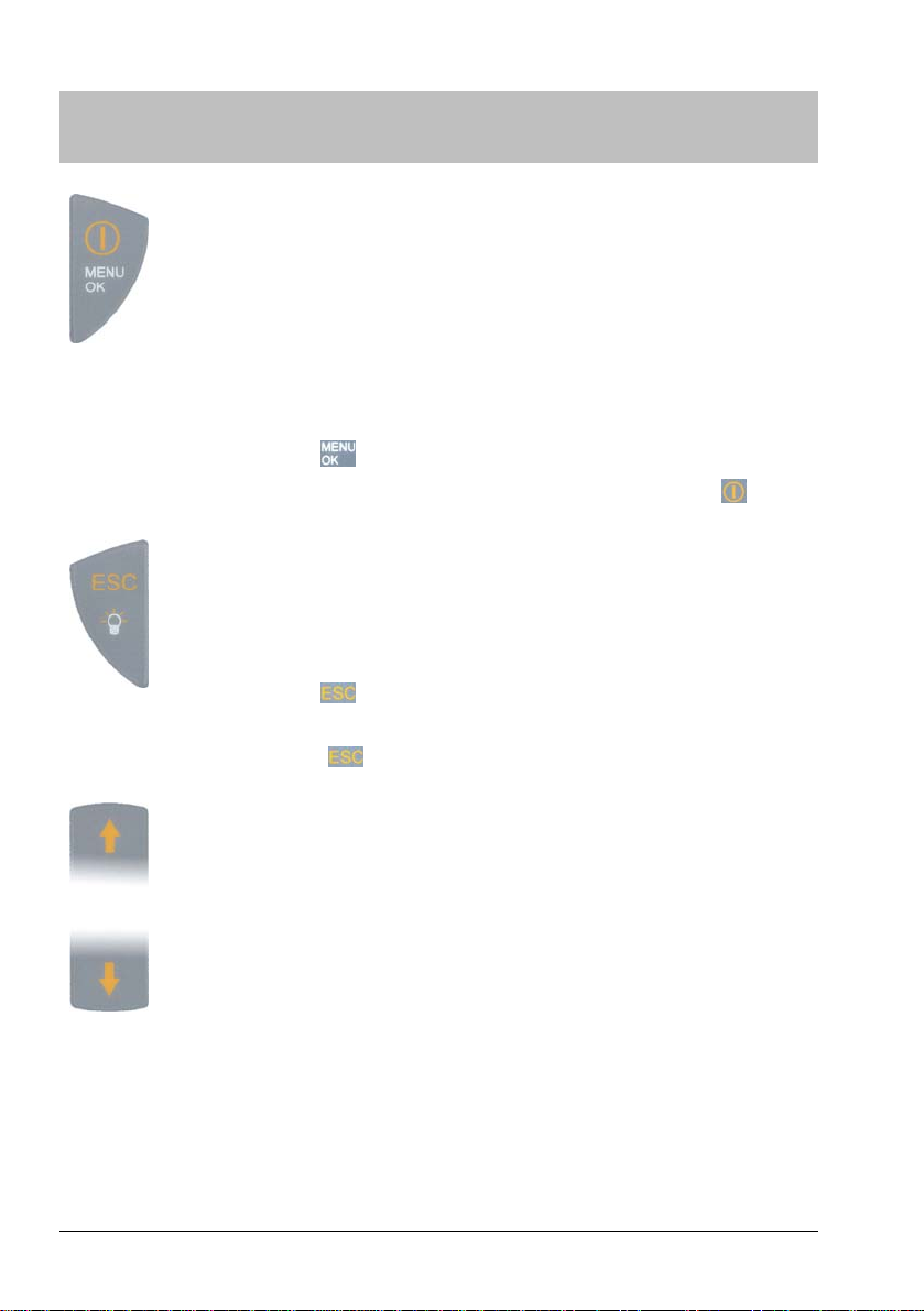
7.1 Key reference _______________________________________________________8
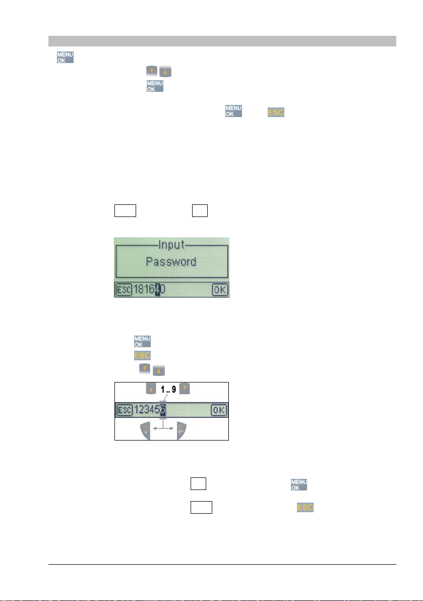
7.2 Operating___________________________________________________________9
7.2.1 Input of alpha-numeric values____________________________________9
8Putting into operation ____________________________________________________10
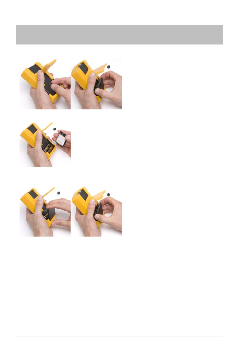
8.1 Insertion of battery, change of battery __________________________________10
8.2 Switching on/off ____________________________________________________11
8.3 Display____________________________________________________________11
8.3.1 Standard representation _______________________________________12
8.3.2 Statistics representation _______________________________________12
8.3.3 Analog representation_________________________________________12
8.4 Additional symbols and abbreviations in the display ______________________13
8.5 Placing the probe ___________________________________________________14
8.5.1 Particularities when placing NFe micro probes______________________14
8.5.2 Placing pressure _____________________________________________15
9Menu structure __________________________________________________________16
10 Menu: Selections and functions in detail_____________________________________19
10.1 Calibration_________________________________________________________19
10.2 Measure ____________________________________________________19
10.2.1 Measuring mode ______________________________________19
10.2.2 Limits ________________________________________________21
10.2.3 Offset ________________________________________________21
10.3 Statistics _____________________________________________________22
10.4 File Management _________________________________________________23
10.5 System Settings _____________________________________________26
10.5.1 Printer _____________________________________________________26
10.5.2 Unit ________________________________________________26
10.5.3 Analog Display _________________________________________27
10.5.4 Backlight ____________________________________________28
10.5.5 Volume _____________________________________________28
10.5.6 Keysound ___________________________________________29
10.5.7 Power Off ___________________________________________29
10.5.8 Hotkeys ____________________________________________29
10.5.9 Lock Keyboard _________________________________________30
10.5.10 Module Code ________________________________________30
10.5.11 et ClockS ________________________________________________30

10.5.12 Language __________________________________________ 30
10.5.13 Load Factory Set. ____________________________________ 30
10.5.14 Info _______________________________________________ 31
11 Do I need to calibrate manually?___________________________________________ 31
12 Calibration_____________________________________________________________ 32
12.1 General notes on calibration _________________________________________ 32
12.2 Calibration Modes__________________________________________________ 33
12.2.1 ZeroCal (Calibration on uncoated specimen) _______________ 33
12.2.2 Cal on Foil (Calibration on zero and foil) __________________ 34
12.2.3 Multipoint Cal (Multiple point calibration) _______________________ 35
12.2.4 Cal on Layer (Calibration on unknown coating) __________________ 36
12.2.5 Load Cal _______________________________________________ 37
12.2.6 Save Cal _______________________________________________ 37
12.2.7 Cal Info ____________________________________________ 37
12.2.8 Default Cal _________________________________________ 38
13 Notes on measurement and calibration _____________________________________ 39
13.1 Influences on measurement accuracy _________________________________ 39
13.2 Regular check of the measuring means ________________________________ 40
14 Format of the printer output ______________________________________________ 41
15 Cleaning of the instrument _______________________________________________ 41
16 Disposal_______________________________________________________________ 42
17 Declaration of conformity ________________________________________________ 42
18 Technical Data _________________________________________________________ 43
Instruction Manual LEPTOSKOP 2042 Art. No. 7423.421 3

1 Scope of delivery
Fig. 1: The LEPTOSKOP 2042 in the
carrying case (equipment example)
yLEPTOSKOP 2042 in protective
holster
y2 batteries, size AA
yinstruction manual
yquality test certificate
ycarrying case
in addition, optionally*:
ysets of calibration foils
ytest block Fe
test block NFe
yprobes
yPC software "EasyExport"
yPC software "EchoStat 2002"
y
y* depending on scope of order
2 About this manual
The LEPTOSKOP 2042 is available in several upgrade levels and can be
enhanced via an unlock code whenever you want. This manual deals with all
upgrade levels. Descriptions which possibly are true only for individual up-
grade levels are designated as follows:
Symbol Upgrade Level
Basic unit
Module "Statistics"
Module "Statistics & Data Memory"
Instruction Manual LEPTOSKOP 2042 Art. No. 7423.421
4

3 Application range
yWith NFe probes the gauge is used to measure the thickness of electrically
non-conductive coatings on non-magnetic electrically conductive sub-
strates (e.g. aluminium, brass, copper) by means of the eddy current
method (DIN EN ISO 2360).
yWith Fe probes the gauge is used to measure the thickness of non-
magnetic coatings on magnetic substrate (e.g. iron, steel) according to the
magnetic-inductive principle (DIN EN ISO 2178).
4 Important notes (read prior to first start-up!)
yThe gauge must not be used in explosive environment. Follow your respec-
tive safety rules.
yDon't switch the instrument on or execute measurement while it is exposed
to electromagnetic interference fields!
Keep the measurement set-up (instrument, cable, test block etc.) away
from sources of magnetic fields (neon light, transformers, mains units, elec-
tric motors etc.)!
This will avoid influences on the measurement result by external magnetic
fields and magnetization of parts under test.
yIf interference fields have been detected...
… the display will show the symbol
… measurement is not possible (the last measured value will remain on
the display)
… an acoustic error signal is generated.
yEnsure that the substrate is free of magnetic remanence to a large extent.
yUse test blocks only to check the proper function of the instrument. If a
special measurement calibration is required (see section 12) you need to
use the actual substrate for calibration.
yWith soft layers even a slight contact pressure may deform the surface and
falsify the measuring result. In this case try to place the probe without
spring force. Or select a compensating offset value (see section 10.2.3) if
either the upgrade level "Statistics" or "Statistics & Data Memory" is
installed.
yThe LEPTOSKOP 2042 is equipped with a monitoring unit for the battery
capacity which will switch the gauge off if a non-sufficient voltage supply is
detected. Prior to final switch-off caused by an empty battery an alarm
sound is generated. Set-up and calibration is memorized.
Instruction Manual LEPTOSKOP 2042 Art. No. 7423.421 5

5 Contacting KARL DEUTSCH
We work flexitime. During the core hours you surely can contact us:
Monday through Thursday 9.00 am to 12.15 pm / 12.45 pm to 15.30 pm
Friday 9.00 am to 12.15 pm
Phone (+49 -202) 7192-0
Fax (+49 -202) 714932
Internet homepage www.karldeutsch.de
Mail can be sent to KARL DEUTSCH
Prüf- und Messgerätebau
GmbH + Co KG
P.O. Box 132354
D-42050 Wuppertal
Office address KARL DEUTSCH
Prüf- und Messgerätebau
GmbH + Co KG
Otto-Hausmann-Ring 101
D-42115 Wuppertal
Instruction Manual LEPTOSKOP 2042 Art. No. 7423.421
6

6 Controls, interface and cable
1Display
2Keyboard
3Data interface for
a) Cable 1657.311 to connect to the 9-pin RS232 in-
terface of a PC.
b) Cable 1657.312 to connect to the USB interface of
a PC.
c) If the cable 1657.311 is completed with the adapter
1657.310 you can connect the printer 6010.001.
4Probe connector
(marked with a red dot)
&Position the probe plug so both red dots, each on
the plug and on the socket, point to the same di-
rection.
5 Type label
6 Pop-up stand
7Battery compartment
Instruction Manual LEPTOSKOP 2042 Art. No. 7423.421 7

7 Keys and menu operation
7.1 Key reference
•ON / OFF key
•Confirmation of input or of the indicated value
•Menu call
•Activation of the marked menu item (selected menu topics are
shown in inverted characters)
•With input: Moves the cursor to the right.
&In the further course of the text this key is repre-
sented by
&The tactile feedback of the key is under the symbol .
•Quitting the current menu item -> move one menu level upward
•With input: Moves the cursor to the left
•In measurement mode: Illumination ON
&
In the further course of the text this key is repre-
sented by t.
&
The tactile feedback of the key is under the
characters .
•Move selection bar of the menu upward. Selected menu topics
are shown in inverted characters.
•Increment (i.e. increasing the indicated value)
•Move selection bar of the menu downward. Selected menu top-
ics are shown in inverted characters.
•Decrement (i.e. decreasing the indicated value)
Instruction Manual LEPTOSKOP 2042 Art. No. 7423.421
8

7.2 Operating
ycalls the operating menu.
yUse the arrow keys to move to the desired menu item and activate it
by pressing the key . If required the same method is used to branch into
additional sub-menus.
ySelections are confirmed by pressing . Use to quit the menu topic
without activation and to return to the next higher menu level (see menu
structure in section 9).
7.2.1 Input of alpha-numeric values
Some selections (e.g. offset, limit, password, time, file name etc.) use alpha-
numeric inputs.
yDisplay: ESC _XXXXX__ OK , where XXXXX is the current parameter
value.
Fig. 2: Input of password
(example)
yOperating: Key : Used to shift the input cursor to the right
Key : Used to shift the input cursor to the left
Keys : Select content of the current input position
Fig. 3: Key assignment with
numeric input (example value)
yConfirm: Shift cursor over OK and strike the key .
yQuit: Shift cursor over ESC and strike the key .
Instruction Manual LEPTOSKOP 2042 Art. No. 7423.421 9

8 Putting into operation
8.1 Insertion of battery, change of battery
open:
(a) (b)
(c)
close:
(d) (e)
Fig. 4: Battery compartment on the rear of
the instrument
yPrior to first putting into opera-
tion you need to insert batteries.
For this purpose two 1.5 V al-
kali-manganese cells of size AA
(Mignon) are part of the delivery.
&
Only change batteries if the
gauge is switched off.
&
You need not to remove the
protective holster when chang-
ing the batteries.
yUse the knurled screw to open
the battery compartment on the
rear of the instrument (a).
yRemove the cover of the battery
compartment (b+c). Now the
batteries are freely accessible.
yThe graphical symbol in the bat-
tery compartment informs on the
proper orientation when insert-
ing the batteries.
yRe-assembly is made in reverse
order.
&
For easy assembly, please en-
sure that the battery cover is
not pressed down (e) before it
is inserted into the bottom slot
between housing and protec-
tive holster (d).
Instruction Manual LEPTOSKOP 2042 Art. No. 7423.421
10

8.2 Switching on/off
SWITCHING ON: SWITCHING OFF:
needs to be pressed briefly. Wait
for the beep.
needs to be pressed for approx. 3 s .
Wait for the beep. The calibration will be
memorized.
&
When switching the gauge on a start measurement is executed, which
expects the probe to be lifted. Thus do not place the probe during
switch-on. Otherwise the error message Lift probe ! will be shown
accompanied by three short alarm beeps.
&
After first switch-on you may start measurement without prior calibra-
tion using the factory setup. Note the information in section 12.
8.3 Display
Depending on the operation mode the readings, evaluations and measure-
ment modes are displayed via various display modes.
In the following the screen contents of the display modes Standard, Statistics
and Analog Representation are explained in detail. Information on possible
additionally shown symbols and messages can be found in section 8.4.
The various display modes become automatically activated and are suitable
for the current operation mode. In addition, they can be selected in turn via
the arrow keys: Normal -> Statistics -> Analog -> Normal ->Statistics -> ...
etc.
Instruction Manual LEPTOSKOP 2042 Art. No. 7423.421 11

8.3.1 Standard representation
(1) Probe type
(2) Symbol, if printer output is active
(3) Reading (after switch-on and with illegal values
3 horizontal lines are shown at first, in all other cases
you will see the current reading)
(4) Battery capacity
(4 levels: empty full)
(5) Measuring indication
= idle in measuring mode "Single"
= idle in measuring mode "Continuous"
= measuring
(6) Measurement unit (µm, mm, mil or inch)
(7) Warning notice: the instrument is subjected to an
interference field (see section 4): eliminate the inter-
ference field and repeat measurement!
(8) Symbol is shown if no probe is connected
8.3.2 Statistics representation
(1) Probe type
(2) Number of readings
(3) Current reading (after switch-on and with illegal val-
ues 3 horizontal lines are shown at first, in all other
cases you will see the current reading)
(4) Measuring indication (as in 8.3.1)
(5) Minimum value (bottom) and maximum value (top)
(6) Arithmetic mean
(7) Measurement unit (µm, mm, mil or inch)
(8) Standard deviation according to
8.3.3 Analog representation
(1) Measuring range
(2) Analog scale
(3) Measurement and indication unit
(4) Probe type
(5) Current reading (digital)
(6) Measuring indication (as in 8.3.1)
Instruction Manual LEPTOSKOP 2042 Art. No. 7423.421
12

8.4 Additional symbols and abbreviations in the display
Instrument is subjected to an interference field, measurement is
not possible
Display of the entered limit values (maximum value top, mini-
mum value bottom)
Display of the entered offset value
OVL The measured value lies outside the accepted measuring
range of the connected probe (remedy, if the estimated meas-
ured value lies within the valid measuring range and a false
measurement or false calibration can be assumed: repeat
measurement/calibration and/or reset gauge to factory settings,
see section 12.2.8)
UART Brief display indication on the initialisation of the interface
Points to the fact that the indicated reading is one reading
within a sequence of readings and is used to determine the lo-
cal thickness (see section 10.2.1), the example shows "5th
reading out of 20".
Fe The connected probe is detected as Fe probe
NFe The connected probe is detected as NFe probe
Reading is above the upper limit (see 10.2.2)
Reading is below the lower limit (see 10.2.2)
The gauge has recognized a connection to a USB interface
Power supply comes from a connected mains unit.
If a measuring file is loaded: Information on the name of folder
(top) and file (bottom)
Instruction Manual LEPTOSKOP 2042 Art. No. 7423.421 13

8.5 Placing the probe
&
In order to exclude systematical and environmental or instrument
caused errors with high probability, we recommend, before starting
and regularly during a measurements series to perform verification
measurements with known coating thickness and known substrates.
yPlace the ball tip of the probe onto the coating to be measured and hold the
measuring probe as perpendicular as possible to the material surface.
With the straight single pole probe the integrated guide sleeve helps:
Fig. 5: Placing the one-pole probe with the aid of the guiding sleeve
8.5.1 Particularities when placing NFe micro probes
&
Due to its geometry the micro probe is particularly sensitive to tilting,
i.e. when using the micro probe for measurement you need to ensure
that the probe is kept perpendicular to the substrate.
Thus, in order to gain a high repetitive measurement accuracy we recom-
mend the use of a
yPositioning device (e.g. KARL DEUTSCH art. no. 2820.002) or a
yPositioning aid (e.g. KARL DEUTSCH art. no. 2998.001 – micro probes 0°,
2998.002 – micro probes 45°, 2998.003 – micro probes 90°),
when measurement is executed by means of the probes
yNFe micro probe 2420.201 (straight)
yNFe micro probe 2420.202 (angled for 45 º)
yNFe micro probe 2420.203 (angled for 90 º)
Instruction Manual LEPTOSKOP 2042 Art. No. 7423.421
14

Fig. 6: Positioning device (left) and various positioning aids (right) for the micro probe
&
The image shows the complete unit. However, if you want to optimize
the positioning device according to your specific needs, the horizontal
arm of the positioning device together with a suitable probe specific
holder and the pneumatic layering unit (colour marked) is available
separately.
8.5.2 Placing pressure
Select the placing pressure so a secure contact to the surface is assured,
however, the does not become dented.
&
Soft coatings: Even a low placing pressure can cause surface defor-
mations in the case of low coating hardness. With soft coatings you
should place the probe with the least possible pressure. Probes with
an integrated spring-loaded guide sleeve should be placed without
spring assistance, if possible.
Instruction Manual LEPTOSKOP 2042 Art. No. 7423.421 15

9 Menu structure
The symbol in the following table denotes standard values after reset of the
instrument to factory settings (see 10.5.13). Additional description to be
found in section 10.5.13. The column "available in" shows which menu topics
are available in which module extension of the instrument.
Basic instrument
Module "Statistics"
Module "Statistics & Data Memory"
Level Menu topics available in
1 Calibration
2 ZeroCal
2 Cal on Foil
2 Multipoint Cal
2 Cal on Layer
2 Load Cal
2 Save Cal
2 Cal Info
2 Default Cal
3 Default Cal ok
1 Measure
2 Measuring mode
3 Single
3 Continuous
3 Local Average
2 Limits
3 Off
3 On
3 Set Limits
2 Offset
3 Off
3 On
3 Set Offset
Instruction Manual LEPTOSKOP 2042 Art. No. 7423.421
16

Instruction Manual LEPTOSKOP 2042 Art. No. 7423.421 17
Level Menu topic available in
1 Statistics
1
2 Off
2 On
2 Delete Values only, if statistics = "On"
2 Edit Values only, if statistics = "On"
2 Print Values only, if statistics = "On"
1 File Management
2 Close File
2 Open File
2 Create File
2 Rename File
2 Delete File
2 File Info
2 Create Folder
2 Rename Folder
2 Delete Folder
2 Delete ALL
3 Delete ALL ok?
4 Are you sure?
1 System Settings
2 Printer
3 Off
3 On
2 Unit
3 µm
3 mm
3 mil
3 inch
2 Analog Display
3 Range AUTO
3 Range fix
3 Range Limits
3 Off
2 Backlight
3 Off
3 Normal
3 Bright
1The selected statistics mode is kept when resetting to factory setting.

Instruction Manual LEPTOSKOP 2042 Art. No. 7423.421
18
Level Menu topic available in
2 Volume
3 Off
3 Low
3 High
2 Keysound
3 Off
3 On
2 Power Off
3 10 min.
3 Never
2 Hotkeys
3 Off
3 On
2 Lock Keyboard
2 Module Code
2 Set Clock
2 Language
2 3
3 Deutsch
3 English
3 Français
3 Español
3 Italiano
3 Português
3 Svenska
3 Polski
3 Czech
3 Românǎ
2 Load Factory Set.
3 Factory Set. Ok
2 Info
2The selected language is kept when resetting to factory setting.
3The stated languages may vary depending on customer.

Instruction Manual LEPTOSKOP 2042 Art. No. 7423.421 19
10 Menu: Selections and functions in detail
10.1Calibration
Information on the calibration modes and possible selections can be found in
section 12.
10.2Measure
10.2.1 Measuring mode
Determines the number of readings gained after placing of the probe.
Single: One measured value after placing of the probe.
Continuous: Continuous acquisition of readings after placing of the
probe (1 reading per second approx.).
&
Depending on the given measurement situation it
may be possible that the last reading in measur-
ing mode "Continuous" is shown only just before
lift-off of the probe.
Local average: only with module
With this testing method the significant test field4is
subdivided into small individual test fields, on which in
each case a given number of measurements is carried
out (example in
d
ted.
Fig. 7: n1 to n9). For these individual
test fields the arithmetic mean value is calculated (ex-
ample in Fig. 7: individual mean values X1 to X12) an
indicated as final measured value and is stored – if the
data memory is activa
n2
n3
n4
n5 n8
n6 n9
n1 n7 n2
n3
n4
n5 n8
n6 n9
n1 n7 n2
n3
n4
n5 n8
n6 n9
n1 n7 n2
n3
n4
n5 n8
n6 n9
n1 n7
n2
n3
n4
n5 n8
n6 n9
n1 n7
n2
n3
n4
n5 n8
n6 n9
n1 n7
n2
n3
n4
n5 n8
n6 n9
n1 n7 n2
n3
n4
n5 n8
n6 n9
n1 n7 n2
n3
n4
n5 n8
n6 n9
n1 n7
n2
n3
n4
n5 n8
n6 n9
n1 n7 n2
n3
n4
n5 n8
n6 n9
n1 n7 n2
n3
n4
n5 n8
n6 n9
n1 n7
X1 X2 X3 X4
X8X7X6X5
X9 X10 X11 X12
When starting this menu
topic first of all the number
of measurements per indi-
vidual test field is entered
(nx).
Up to 20 measurements
per individual test field are
possible.
Fig. 7: Significant test
field and allocation into
individual test spots
4the significant test field represents a surface field, that is typical for the object of measurement with regard
to the substrate qualities as well as the coating application and coating specifications

Display with data acquisi-
tion:
(1) Mean value of a individual
test field (in each case the
last determined value)
(2) Measurement counter for
the individual measure-
ments in format n/m
where
n = current measurement
m = number of measure-
ments per individual
test field
(3) = current individual value
Display after acquisition of
the mth measured value:
(1) Mean of the individual test
field
(2) Last individual reading
before calculation of the
mean value
Instruction Manual LEPTOSKOP 2042 Art. No. 7423.421
20
Table of contents
Other KARL DEUTSCH Measuring Instrument manuals
Popular Measuring Instrument manuals by other brands

Gazelle
Gazelle G9407-Log Operating instruction

ABB
ABB SM3000 instructions

Agilent Technologies
Agilent Technologies E4445A PSA Series Service note

Sinar
Sinar AP 6060 user manual

Pentair
Pentair EVERPURE EV4339-31 quick start guide

PCB Piezotronics
PCB Piezotronics IMI Sensors M602D01 Installation and operating manual