manuals.online logo
Brands
  1. Home
  2. •
  3. Brands
  4. •
  5. Deif
  6. •
  7. Measuring Instrument
  8. •
  9. Deif BRW-2 User manual

Deif BRW-2 User manual

BRW-2
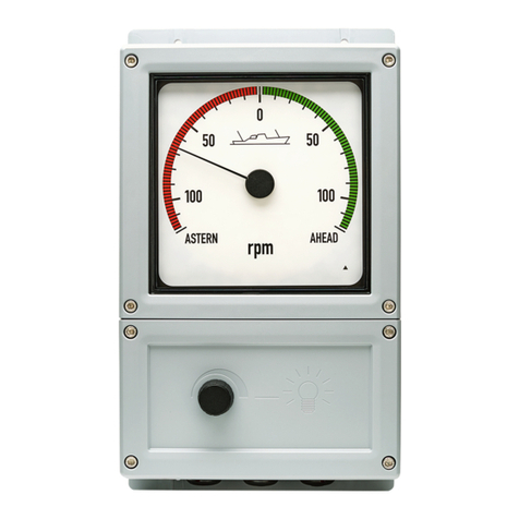
Bridge wing indicator
Quick guide
4189350056B
1. Mounting the unit
Dimensions and drilling plate
NOTE The three PG21 type cable glands on the bottom of the unit are suitable for cable gauge 13 to 18 mm.
QUICK START GUIDE 4189350056B UK Page 2 of 4
2. Wiring of analogue version
NOTICE
Warranty is void if the warranty seal is removed or broken
Powering up
The pointer position is random until the power supply is connected. On power-up, the pointer will move randomly for the
first couple of seconds. This is normal operation. Also on power-up, the amber LED in the lower right corner of the scale
area will flash once or twice and then turn off.
Analogue version
There is a “maximum” and a “zero” adjustment on the rear side of the XL part. These are factory-sealed.
BRW-2 analogue input: See the user's manual for guidance on how to adjust this version.
Terminal connections on interface board
Pin no. Function Notes
1 Supply voltage 0 V
24 V 2
3
Analogue input
Input 1 (sin) Input 1 and GND used for single input. On 4 to 20 mA, Input 1 is CW
and Input 2 is CCW.
Note: GND is mutual for Input 1 and Input 2 .
4 GND
5 Input 2 (cos)
8 NC No connection.
9
X4 connector
illumination
Orange wire Dimmer potentiometer (10 kΩ).
10 Brown wire
11 Red wire Wiper on the dimmer potentiometer.
A
Analogue adjustment
Max. adjustment Max. adjustment, factory-sealed with label. Located on back of the
XL 192.
B Zero adjustment Zero adjustment, factory-sealed with label. Located on back of the
XL 192.
QUICK START GUIDE 4189350056B UK Page 3 of 4
3. sCAN version
Setup
Special means for minimum, zero and maximum setting of the pointer are provided. Pointer direction of rotation can also be
changed.
Wiring of CAN version
Use strips to terminate cable shields to PCB to avoid noise (see the dashed circles in the diagram). Jumpers J1 and J2 are
used to connect CAN 1 and CAN 2 termination resistors.
Pin no./designation Function Note
GND
CAN connection
CAN 2 GND
CAN 2 line/or for external switch for calibrating sCAN
(see user’s manual).
L input CAN 2 L input
H input CAN 2 H in put
GND CAN 1 GND
CAN 1 line (sCAN line). L input CAN 1 L input
H input CAN 1 H input
24 V Supply voltage 24 V DC
0 V 0 V DC
9
X4 connector Illumination
Orange wire Dimmer potentiometer (10 kΩ).
10 Brown wire
11 Red wire Wiper on dimmer potentiometer.
Powering up
On power-up, the LED will flash once and then switch off. If the LED continues to flash this means there is no
communication with the CANopen lines. Default communication baud rate is set to 125 kbit/s.
NOTICE
Do not connect the cable shield to earth.
Never connect the cable shield to earth. If there is noise interrupting communication, try to connect the cable
shield to the respective CAN GND on all devices in the loop. Do not connect the two cable shields together.
QUICK START GUIDE 4189350056B UK Page 4 of 4

Other manuals for BRW-2

2

Other Deif Measuring Instrument manuals

Deif WSI User manual

Deif

Deif WSI User manual

Deif XL User manual

Deif

Deif XL User manual

Deif XDi Series User manual

Deif

Deif XDi Series User manual

Deif BRW-2 User manual

Deif

Deif BRW-2 User manual

Deif DLQA96 User manual

Deif

Deif DLQA96 User manual

Deif ADL-111Q96/xxVDC Series Installation instructions

Deif

Deif ADL-111Q96/xxVDC Series Installation instructions

Deif MIC-2 MKII User manual

Deif

Deif MIC-2 MKII User manual

Deif BRW-2 User manual

Deif

Deif BRW-2 User manual

Deif MIB 8000 User manual

Deif

Deif MIB 8000 User manual

Deif MIC-2 MKII Operating and maintenance instructions

Deif

Deif MIC-2 MKII Operating and maintenance instructions

Deif MIQ96-2 User manual

Deif

Deif MIQ96-2 User manual

Deif MIB 7000 User manual

Deif

Deif MIB 7000 User manual

Deif Insight User manual

Deif

Deif Insight User manual

Deif AGC 150 User manual

Deif

Deif AGC 150 User manual

Deif TRI-2 User manual

Deif

Deif TRI-2 User manual

Popular Measuring Instrument manuals by other brands

Scarlet Tech WR-3 user guide

Scarlet Tech

Scarlet Tech WR-3 user guide

Telegesis ZigBee RangeFinder ZHT100 quick start guide

Telegesis

Telegesis ZigBee RangeFinder ZHT100 quick start guide

Jula 730-028 operating instructions

Jula

Jula 730-028 operating instructions

INSTRUMENTYS CB Q1 instruction manual

INSTRUMENTYS

INSTRUMENTYS CB Q1 instruction manual

Hioki 3532-50 instruction manual

Hioki

Hioki 3532-50 instruction manual

SICK FLOWSIC100 Flare ADDENDUM TO OPERATING INSTRUCTIONS

SICK

SICK FLOWSIC100 Flare ADDENDUM TO OPERATING INSTRUCTIONS

JXCT JXBS-3001-SCY instruction manual

JXCT

JXCT JXBS-3001-SCY instruction manual

Koso DB-01R instructions

Koso

Koso DB-01R instructions

Chauvin Arnoux P 310 user manual

Chauvin Arnoux

Chauvin Arnoux P 310 user manual

VDO TACHOMETER WITH COUNTER installation instructions

VDO

VDO TACHOMETER WITH COUNTER installation instructions

PICO TA386 user guide

PICO

PICO TA386 user guide

Würth ORSY-Mobil 4 installation instructions

Würth

Würth ORSY-Mobil 4 installation instructions

Stuart SMP50 Instructions for use

Stuart

Stuart SMP50 Instructions for use

Circutor CVM-B100 instruction manual

Circutor

Circutor CVM-B100 instruction manual

UINICS SP-564A Series instruction manual

UINICS

UINICS SP-564A Series instruction manual

AR DC7164 Operating and service manual

AR

AR DC7164 Operating and service manual

Techly IPW-ADP-ENM2 instruction manual

Techly

Techly IPW-ADP-ENM2 instruction manual

Laserworld GREEN-200E user manual

Laserworld

Laserworld GREEN-200E user manual

manuals.online logo
manuals.online logoBrands
  • About & Mission
  • Contact us
  • Privacy Policy
  • Terms and Conditions

Copyright 2025 Manuals.Online. All Rights Reserved.