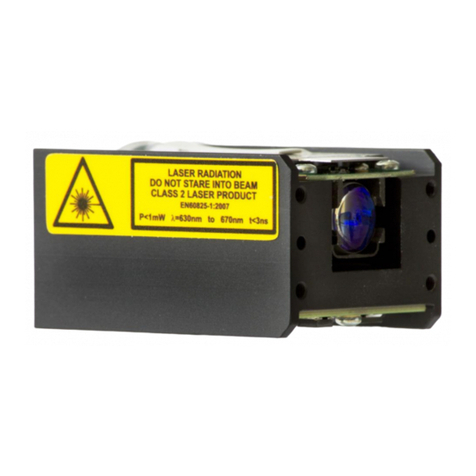
Jenoptik JenLas D2 Series User manual

Disk Laser
JenLas®D2.x
Installation Instructions

2
JENOPTIK l Healthcare & Industry
JENOPTIK Laser GmbH
Goeschwitzer Str. 29
D-07745 Jena
(Germany)
Service Department:
Phone: + 49 3641 65-2102
Fax: + 49 3641 65-2109
Email: laser[email protected]
Internet: http://www.jenoptik-los.com
You can use the --> 5 Fax Form p. 16, for your requests.
In the case of need, copy this form, fill it in and send it to the above address.
Documentation No.: 012236-025-98-02-2001-en
17 th issue, January 2016
Subject to changes.

3
Dear user
Knowledge of the information provided by this Installation Instructions is
absolutely necessary.
The specications provided are an integral part of the Installation Instructions in
hand.
Therefore, to fully exploit the capabilities of the system, please study this manual
thoroughly and particularly observe the notes regarding its safe use.
The equipment is subject to changes due to ongoing product development.
This documentation is not included in any update service.
© Unless expressly authorized in writing by JENOPTIK Laser GmbH, forwarding
and duplication of this document, and the utilization and communication of
its contents are not permitted. Violations will entail an obligation to pay com-
pensation.
All rights reserved in the event of granting of patents or registration of a util-
ity model or design.
Published by: JENOPTIK l Healthcare & Industry
JENOPTIK Laser GmbH
Goeschwitzer Str. 29
D-07745 Jena
(Germany)
Phone: + 49-3641-65 3053
Fax: + 49-3641-65 4011
E-mail: laser.service@jenoptik.com
Internet: http://www.jenoptik.com/solidstatelasers
Dear user

4
In this documentation, the following characters, symbols and pictograms are be-
ing used:
Note
--> Cross-reference to sections or illustrations of this manual
• Operations to be performed
Enumeration
Danger: Warning
Warning symbols
Supplements (further pertaining documents):
Test Certificate of final inspection
Warning: Risk to human health in the case of non-observance.
Caution: Possible damage to the device.
Warning: Emission of visible and invisible laser radiation.
Caution: Components are sensitive to electrostatic discharge damage.
Dear user

5
Contents
1Safety Notes .......................................................................................6
1.1 Warning labels and type label................................................................. 7
1.2 General................................................................................................... 7
1.3 RoHS Directive........................................................................................ 8
2Installation..........................................................................................9
3Technical Data ..................................................................................14
3Appendix ..........................................................................................15
4Fax Form...........................................................................................16
Contents

6
1 Safety Notes
Warning: Laser radiation!
The Disk Laser may be installed and put into operation only by appropriately
qualified and instructed personnel.
Make sure the device is not used improperly.
The device does not contain any safety devices such as shutters, emission
warning lamps, emergency stop button, power switch, etc.
Never look directly into the laser beam.
Emitted visible and invisible laser radiation may cause irreversible skin and
eye injury and result in changes to organic materials.
Wear laser protective eyewear as per EN 207 (Protection DI L5), while the
laser is operated with uncovered optical path.
Observe all relevant local and national safety regulations. The laser is a Class 4
laser device as per EN 60825-1 (IEC 60825-1).
Observe the relevant local safety regulations for the operation of laser
devices (in Germany: Regulations for the Prevention of Accidents BGV B2).
Make sure to avoid back reflections into the disk laser.
This may result in destruction of the device and make void all warranty
claims.
Preclude creeping fats and oils from getting into the disk laser!
You are not allowed to mechanically modify the device or loosen any screws.
Non-observance can discharge additional laser radiation and will make void
any liability and warranty claims.
The responsibility for the combination of the device with components and
units of other manufacturers solely lies with the owner/operator.
Make sure to keep any objects away from the laser area, which do not
conform to the intended use of the device.
The Disk Laser must not be operated in explosion-risk areas. The device does
not meet the requirements of the EC Directive 94/9/EC.
During laser operation, substances that are harmful to human health may be
generated in the form of aerosols, gases and/or dusts.
Caution: Diode current!
The device has no current limiter.
Therefore, make sure the maximum diode current is not exceeded.
The safety notes contained in these installation instructions exclusively apply, if
the parameters of the --> Test Certicate are complied with.
Improper use makes void any liability and warranty claims.
Caution: Flammability!
Do not expose explosive, ammable and/or combustible materials to the laser
beam.
Caution: Accumulation of heat!
Ensure appropriate heat dissipation by a suitable cooling unit!
Safety Notes

7
1.1 Warning labels and type label
VISIBLE AND INVISIBLE LASER RADIATION
AVOID EYE OR SKIN EXPOSURE
TO DIRECT OR SCATTERED RADIATION
CLASS IV LASER PRODUCT
EN 60825-1:2007
max. 3.5/6 W
max. 10 m W
P
λ
1064 nm
P
λ
532 nm
EMERGENT PORT
FOR VISIBLE AND INVISIBLE
LASER RADIATION
!
JenLas D2
..............
®
Serial No.: ........................
JENOPTIK
Laser GmbH
D-07739 Jena
Made in Germany
Type:
Manufactured:
Type label
ATTENTION
Electrostatic sensitive device
Observe precautions for
handling
The removal or breaking of the seals
immediately makes the warranty void
Entfernen oder Brechen des Siegels
führt zum Gewährleistungsverlust
DE 59 407 111
EP 0 632 551 WO 99/08728 US 6.711.184 B1
EP 0 869 591 DE 59 901 655
EP 0 869 592 US 6.577.666
US 5.553.088 JP 2002 524839
EP 1 103 090 EP 0 911 920
THIS PRODUCT IS MA NU FACTURED
UNDER ONE OR MORE OF THE
FOLLOWING PATENTS
P A T E N T N U M B E R S
- The parameter Pλ532 nm max. depends on the version of the subassembly (see above).
- Removing the Serial No. makes void any warranty claims.
Fig. 1 Warning labels and type label
1.2 General
The Disk Laser is available in two versions:
Pλ532 nm = 3 W Pλ1064 nm = 10 mW and
Pλ532 nm = 5 W Pλ1064 nm = 10 mW
The detailed Technical Data are given in your --> Specifications.
For the operating conditions (temperature, relative humidity, atmospheric pres-
sure), refer to your --> Specifications.
Prior to start-up of the device, make sure it is in perfect condition.
Modifications and repairs of the device are subject to safety regulations and
may only be performed by JENOPTIK Laser GmbH.
Strictly observe all warning labels.
Avoid external contamination of the beam exit window as this would result
in the decrease of the available laser power.
Burnt in dirt will make void any warranty claims.
Disk lasers are very sensitive to overvoltage.
Therefore, the fitter, the workbench and the used tools must be grounded
for installation work.
Safety Notes

8
In inactive mode, absolutely make sure to provide ESD protection
(ESD = electrostatic discharge) by shorting the connection terminals
(if built in, by relay contact, otherwise by a short-circuit bridge).
Prior to opening the packing, make sure the device has normalized to
ambient temperature to avoid condensation.
Keep a period of approximately 2 hours for temperature adjustment.
Keep the original packaging for possible future relocation or transportation
of the device. For storage and transport conditions, refer to your -->
Specifications.
1.3 RoHS Directive
This product is RoHS compliant in accordance with Directive 2011/65/EU on the
restriction of the use of certain hazardous substances in electrical and electronic
equipment.
Safety Notes

9
2 Installation
The mounting holes (6to 9 or 12, Fig. 2), the sub-D connector (5), the electric
terminals (2, 4) and the optical beam exit aperture represent the interface to the
user-specific use of the device.
Make sure to observe the --> Safety Notes, p. 6, to avoid any risk.
Caution: ESD protection!
Avoid any electrostatic discharge and observe the rules for ESD protection. The
fitter, the workbench and the tools used must be grounded.
Note:
The use of controls or adjustments or performance of procedures other than
those specified in this manual may result in hazardous laser exposure. Non-
observance may completely make void any warranty claims.
1 2 5
6
9
12
(12)
7
8
10
11
3
4
1 Contact surface for temperature control
2 Negative terminal (M5)
3 Short-circuit bridge
4 Positive terminal (M5)
5 D-Sub connector
6 Through bores for M4 guiding bolt
7 Through bore for M4 fastening bolt
8 Bore for locating pin (∅3.9 mm pre-drilled)
9 Through bore for M4 fastening bolt
10 Laser exit aperture
11 Threaded bores (M4, 6 mm deep) for mounting an additional optical element
12 Threaded bores (M4, 6 mm deep) for mounting a cooling unit with a Peltier element
Fig. 2 Disk Laser
Installation

10
M4 6 mm tief
70
60
35
85
82 113
5
92.5
178
200
M5
44 11
∅
5.6
∅
5.6∅
4D10
46
12
19.7
∅
3.9
49.5
8
45
26
2.5
53.5
46
12
22
0.8
10
25
25
40
178
23
86
38.5
5
A
0.8
0.65 0.1
±
A
Fig. 3 Geometrical mounting dimensions
Installation

11
Caution: ESD protection!
Avoid any electrostatic discharge and observe the rules for ESD protection. The
fitter, the workbench and the used tools must be grounded.
•Mount the subassembly to an appropriate cooling unit with Peltier cooling
element by means of the screws (6, 7, 9or 12, Fig. 2, p. 9).
The contact surface of the cooling unit must be sufficiently flat and clean.
The cooling capacity of the cooling unit depends on the operating mode.
For this, refer to --> Specifications. Dimension the cooling unit in such a way
that no overheating can occur.
Refer to --> Fig. 3, p. 10 for information on the dimensions and the location of
the threaded holes to be cut into the cooling unit for fastening the subassembly.
•Screw the three threaded bolts provided into the cooling unit, and carefully
attach the laser device.
Note:
To improve thermal transfer, we recommend the use of a thin, solvent-free
heat-conductive film.
The use of a commercial heat-conductive paste is not allowed, as its creep-
ing behavior as well as evaporating solvent may destroy the module.
•Put the delivered spring onto each fastening bolts. The two thin springs have
to be inserted into the bores (6, 7,9, Fig. 2, p. 9).
Then, screw down the device by means of the nuts (Max. torque: 10 cNm
for 6, 7; 40 cNm for 9).
•To secure the mounting position, drill dowel bore (8) into the cooling unit
(approx. 6 mm deep) to a diameter of 4 mm. Then, secure the units by dowels.
When you mount an additional optical element to the front surface of the de-
vice, make sure that its weight does not exceed 500 g (Center of mass: max
150 mm in front of the front surface).
XH1
10 kΩ
3.9 V, 2.3 A
LD
10 kΩ
10 kΩ
X2
X1
NTC/DiodeNTC/Diode
NTC/LBO
Peltier/LBO
LD-
1
2
3
4 PE-
5
6
7
8
9PE+
+
(sw) (rt)
Fig. 4 Pin assignment
•Wire the connecting cable to the sub-D connector as illustrated in the ob-
ove-mentioned scheme.
Installation

12
Installation
•Connect the connection cable to the 9-pin Sub-D connector (4).
Secure the cable by fastening the slotted screws of the connector by means
of a torque-controlled screwdriver adjusted to 0.6 Nm (60 Ncm).
Important:
The use of normal screwdrivers or other tools is not permissible.
Make sure to prevent any impact and tensile load to this connector indepen-
dent of the direction of action.
•The diode current is supplied to the master system through terminals (M5)
(1, 3). Fasten the M5 nuts by means of a torque-controlled screwdriver ad-
justed to 2.5 Nm (250 Ncm).
Important:
When connecting the cable, make sure the wires are correctly polarized, as
already low back voltages may lead to irreversible damage.
The use of an open-end wrench or of other radially acting levers is not per-
missible. Make sure to prevent any impact and tensile load to these terminals
independent of the direction of action.
The diode current supply must meet the following requirements:
Make sure that current and voltage spikes cannot affect the device, neither
during operation nor when switching the diode current supply ON/OFF. This
also refers to indefinite states (e.g. cable break, power failure, etc.).
Even very short current or voltage spikes may destroy the disk laser.
Very important:
It is not allowed to solder the connection cable to the high-power diode laser.
The cables must be arranged in such a way, that no induction is generated
and thus oscillations are avoided.
When the device is switched off, the device must be short-circuited to provide
ESD protection (relay contact).
Caution: Diode current!
The device has no current limiter. Therefore, make sure the maximum diode
current is not exceeded.
Note:
Use a current supply module with current limiting.
The safety notes contained in these installation instructions exclusively apply, if
the parameters of the --> Test Certificate are complied with.
Improper use makes void any liability and warranty claims.
The measurement of the diode temperature and the LBO crystal is based on an
integrated temperature sensor (NTC; 10 kΩ).
The NTC resistance/temperature data is shown in --> Appendix, p. 15.
The nominal temperature of the LBO crystal is adjusted through a Peltier element
with the following parameters:
Imax (A) Umax (V) Pcmax (W)
2.3 3.9 5.2

13
Installation
The temperature regulation should not be faster than 15 K/min.
Caution: Temperature adjustment!
Before applying the diode current, the LBO temperature and the diode tempera-
ture must be adjusted according to the specifications of the --> Device Card.
Make sure that the constancy of LBO temperature and diode temperature com-
plies with your --> Specifications.
To achieve stable output parameters of the thin disk laser we recommend to
keep the LBO temperature stable within < 0.2K and the diode temperature
within < 0.5K
.
•Finally, disconnect the short-circuit bridge (3, Fig. 2, p. 9) between the con-
necting terminals and keep it for future use.
Warning: Laser radiation!
The Disk Laser has no ON/OFF switch.
Laser radiation is instantly emitted when diode current is supplied.
Note for relocation and transport
•Before disconnecting the device electrically, insert the short-circuit bridge (3).
•For relocation or transport, please use the original packaging. Make sure to
close the folding bag after the device was inserted.
•For storage and transport conditions, refer to your --> Specifications.

14
3 Technical Data
Feature Operating data Limit values as per
EN 60825-1
Laser Disk laser
Laser Class 4 as per EN 60825-1:2007
Wavelength 532 nm ± 1 nm
Output power 3/5 W (cw) 10 W (cw)
Power stability (rms) < 3 %
Beam quality M2typ. 5,
coupling into 50-µm ber is possible
Beam size < 2 mm
Divergency < 2 mrad
Polarization > 1 : 100
Orientation horizontal (parallel to groundplate)
Ellipticity (beam cross-section) < 1:1.5
Beam position at exit ± 0.5 mm
Beam direction ± 3 mrad
Pointing stability < 0,1 mrad
Operating mode
Pulsed mode from 1 ms pulse length to cw
(amplitude modulation up to 20 kHz possible)
Ambient conditions
Temperature range
Relative humidity
Atmospheric pressure
+ 5 °C ... + 40 °C
< 90 %, no condensation
700 ... 1060 hPa
Storage and transport conditions
Temperature range
Relative humidity
Atmospheric pressure
Mechanical load examined
accordingly
DIN 15010109
Noise
Single shocks
Continuous shocks
- 20 °C ... + 70 °C
0 ... 90 %, no condensation
700 ... 1060 hPa
9 ... 500 Hz; 3 g
30 g/18 ms
10 g/6 ms
Nominal temperature range of
diodes
+ 20 °C ... + 35 °C
Nominal temperature range of LBO + 25 °C ... + 40 °C
Enclosure Protection IP 41
Electrical connection 2 V, typ. 18 A, ≤ 24 A (at diode laser, 3 W)
2 V, typ. 22 A, ≤ 26 A (at diode laser, 5 W)
max. 3.9 V, 2.3 A (Peltier, LBO)
Input power < 60 VA
Maximum current for nominal power
see --> Test Certicate
Performance of operating processes
in compliance with VDE 0100
Dimesnsions (L x W x H) 200 x 70 x 40 mm
Weight approx. 1.8 kg
Technical Data

15
4 Appendix
NTC resistance temperature values
Type EPCOS G560, 10kΩ @ 25°C / 77 F, Toleranz ∆T ≤ ±1.0°C / 34 F (range
0°C / 33 F to 40°C / 104 F)
Approximation formula:
R(T) = R25 e
T in °C
B = 3450 K
R25 = 10.0 kΩ
TR = 25°C
T [°C] R_nom [kΩ] R_min [kΩ] R_max [kΩ]
0 27.94 27.36 28.52
5 22.47 22.05 22.88
10 18.19 17.89 18.48
15 14.81 14.60 15.02
20 12.14 11.99 12.28
25 10.00 9.900 10.10
30 8.284 8.186 8.383
35 6.899 6.804 6.994
40 5.774 5.684 5.864
45 4.856 4.772 4.940
50 4.103 4.024 4.181
Appendix
( )
BT + 273,15 K T + 273,15 K
R
1 1
( )
BT + 273.15 K T + 273.15 K
R
1 1

16
5 Fax Form
To
JENOPTIK Laser GmbH
Goeschwitzer Str. 29
Service Department:
Fax: + 49-3641-65 4011
Our Ref.: .......................................... Your Ref.: ...............................................
Pages (incl. cover page): ................... Date: .....................................................
Message
(with brief description of faults JenLas®D2.x):
Sender: ........................................................................................................
Company: ........................................................................................................
Address: ........................................................................................................
Telephone: ..................................... Fax No.: ..................................................
Signature: ..............................................
Fax Form
Table of contents
Other Jenoptik Measuring Instrument manuals
Popular Measuring Instrument manuals by other brands

ZURN
ZURN AquaSense AV ZER Series Installation, operation, maintenance and parts manual
Trotec
Trotec T610 operating manual
Keysight Technologies
Keysight Technologies B2980A Series Technical overview
Huato
Huato HE2 A Series Operation manual
YOKOGAWA
YOKOGAWA VY Series manual

Fluke
Fluke 8050A instruction manual
