Karthrein Euroline KEL 4124 User manual

Page 1 of 1
KATHREIN Digital Systems GmbH • Anton-Kathrein-Straße 1–3 • 83022 Rosenheim • Germany
Rosenheim, 31.03.2019
Information über gesellschaftsrechtliche Änderung
Information about change in corporate legal status
Zum 1. April 2019 geht das Geschäftsfeld „Terrestrial & Satellite Reception“ der
KATHREIN SE (vormals KATHREIN-Werke KG) auf die KATHREIN Digital Systems
GmbH über.
Die neuen Firmendaten lauten ab 01.04.2019 wie folgt:
KATHREIN Digital Systems GmbH
Anton-Kathrein-Str. 1–3
83022 Rosenheim, Deutschland
Steuer-Nr.: 156/117/31083
UST-Ident-Nr.: DE311049363
Registergericht: Traunstein, HRB 25841
______________________________________________________________________________
As of 1 April 2019, KATHREIN SE’s (formerly KATHREIN-WERKE KG) “Terrestrial &
Satellite Reception” business unit will be transferred to KATHREIN Digital Systems
GmbH (limited liability company).
From 1 April 2019, the new company data are:
KATHREIN Digital Systems GmbH
Anton-Kathrein-Str. 1–3
83022 Rosenheim, Germany
Tax ID No.: 156/117/31083
VAT Reg. No.: DE311049363
Commercial Register: Traunstein, HRB 25841
KATHREIN
Digital Systems GmbH
Anton
-Kathrein-Straße 1–3
83022 Rosenheim
Germany
www.kathrein
-ds.com
info
@kathrein-ds.com
Executive Board
:
Michael Auer
Uwe Thumm
US
t-ID-Nr.: DE 311 049 363
Steuer
-Nr.: 156/117/31083
GLN:
40 63242 00000 5
WEEE
-Reg.-Nr.: DE 66199153
Registered Office: Rosenheim, DE
Commerc
ial Register: Traunstein, HRB 25841
Commerzbank AG
IBAN:
DE24 7114 0041 0611 9002 00
BIC:
COBADEFFXXX
936500001

1 / 2
Einkabelspeisesystem
Zu dieser Anleitung
Dieses Dokument ist Teil des Produkts.
►Das Speisesystem erst benutzen, nachdem Sie diese Anleitung gelesen und
verstanden haben.
►Die in dieser Anleitung beschriebenen Maßnahmen immer in der angege-
benen Reihenfolge durchführen.
Merkmale
Das Einkabelspeisesystem KEL4124 eignet sich für Satellitenempfangsanlagen,
bei denen bis zu 24 Teilnehmer zu versorgen sind. Es ist zum Empfang von Satel-
liten im ku-Band bestimmt, z.B. ASTRA, EUTELSAT, Türksat und Hispasat.
Lieferumfang
■KEL4124 ■Gebrauchsanleitung
Montage
Sicherheitshinweise
Vor der Montage des Speisesystems die Sicherheitshinweise in der Anleitung
der Kathrein Euroline-Parabolantennen lesen.
Die Sicherheitshinweise für Parabolantennen und Speisesysteme sind identisch.
Speisesystem montieren
1. Speisesystem zwischen Unter- und Oberteil der Speisesystemhalterung
einklemmen und mittels der Schraube locker anschrauben (Abb.1).
2. Gradwert für die Polarisationseinstellung aus Abb.2 entnehmen.
3. Speisesystem durch Drehen auf den entsprechenden Winkel einstellen.
4. Speisesystemhalterung fest verschrauben (Abb.3).
Kabelanschluss
1. Auf das Kabel, Kathrein-Typ LCD90, LCD95A+, LCD111A+ oder
LCD115A+, Wetterschutzkappe aufschieben.
2. Das Kabel abisolieren und F-Stecker* (z.B. EMK01) aufschrauben. Dabei
darauf achten, dass keines der Geechtdrähtchen nach der Steckermon-
tage den Innenleiter berührt (Kurzschlussgefahr).
3. Kabel am Speisesystem anschließen.
4. Wetterschutzkappe bis auf Anschlag am Speisesystemgehäuse nach unten schieben.
*) Nicht im Lieferumfang enthalten.
Abb. 2
Standpunkt vor der Parabolantenne
Abb. 1
Abb. 3
Abb. 4
KEL 4124
20110031
WICHTIG
Vor Gebrauch
sorgfältig
lesen!

2 / 2
Einkabelspeisesystem
KATHREIN SE, Anton-Kathrein-Str. 1-3, 83022 Rosenheim, Germany, Telefon +49 8031 184-0, Fax +49 8031 184-52360
936.5393/a/STD/0418/DE | Änderungen vorbehalten.
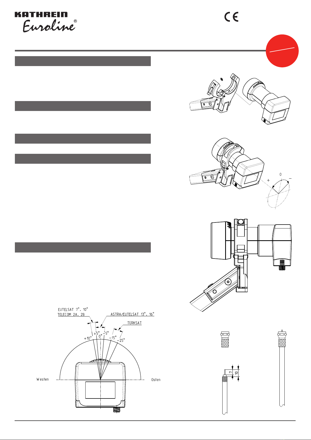
Satellitenempfangsanlage ausrichten
Das Ausrichten der Kathrein Euroline-Satellitenempfangsanlage der Montageanleitung entnehmen, die der Parabolantenne beige-
packt ist. Bei Fremdfabrikaten das Ausrichten der Empfangsanlage der mitgelieferten Produktdokumentation entnehmen.
Technische Daten
Typ Einheit KEL4124
Bestellnummer 20110031
Geeignet für Parabolspiegel KEA650W/G/R, KEA750W/G/R, KEA850W/G/R, KEA1000W/G/R
Eingangsfrequenz GHz 10,70–11,70 und 11,70–12,75
Ausgangsfrequenz MHz 950–2150
Oszillatorfrequenz (L.O.) GHz 10,4
Frequenzzuordnung MHz UB 1: 975, UB 2: 1025, UB 3: 1075, UB 4: 1125, ..., UB 24: 2125
Polarisationsentkopplung dB min.22
Ausgang/Impedanz -/Ω F-Buchse/75
Versorgungsspannung LNB V 11–19
Stromaufnahme LNB mA max.300
Abmessung Feed-Aufnahme (Ø) mm 40
Abmessungen mit Kappe mm 121x70x91
Gewicht ca. kg/St. 0,195
Garantiebedingungen
• Die Garantie bezieht sich ausschließlich auf den Ersatz des Produktes.
• Das LNB muss fachmännisch, unter Berücksichtigung der Vorgaben der beigelegten Gebrauchsanleitung, montiert werden.
• Das LNB darf nicht verändert werden, z.B. durch das Anbohren.
• Das LNB darf mechanisch nicht beschädigt werden, z.B. durch Deformationen nach einem Absturz vom Dach.
• Das LNB darf nicht durch Chemikalien beschädigt werden, z.B. durch Lösungsmittel, Lacke, Reinigungsmittel o.Ä.
• Des Weiteren besteht keine Garantie für die Folgen höherer Gewalt, z.B. durch Blitzeinschlag, Sturm oder Hagel.
• Als Garantienachweis dient ausschließlich die Originalrechnung.
Reparatur und Austausch
Sollten Sie mit den Kathrein Euroline-Qualitätsprodukten wider Erwarten Probleme haben, setzen Sie sich bitte mit Ihrem Fachhändler
bzw. mit unserer Servicestelle in Verbindung. Die Anschrift unserer Servicestelle lautet:
REP and MORE GmbH
Hauptstr. 2a
35792 Löhnberg-Obershausen
Telefon: +49 6477 6123-101
Fax: +49 6477 6123-020
E-Mail: service-kathrein@repandmore.com
Entsorgung
Elektronische Geräte gehören nicht in den Hausmüll, sondern müssen – gemäß Richtlinie 2002/96/EG DES EUROPÄ-
ISCHEN PARLAMENTS UND DES RATES vom 27. Januar 2003 – über Elektro- und Elektronik-Altgeräte fachgerecht
entsorgt werden. Bitte geben Sie dieses Gerät am Ende seiner Verwendung zur Entsorgung an den dafür vorgesehenen
öffentlichen Sammelstellen ab.
KEL 4124
20110031

1 / 2
Single-cable Feed System
About This Guide
This document is part of the product.
►Do not install or use this device until you have read and understood this
document.
►Perform all operating steps described in this manual in the specied
sequence.
Features
The KEL 4124 single-cable feed system is intended for satellite reception
systems in which up to 24 subscribers are to be supplied. It is designed to
receive Ku-band satellites such as ASTRA, EUTELSAT, Türksat and Hispasat.
Scope of Delivery
■KEL4124 ■Instructions for Use
Installation
Safety Instructions
Before installing the feed system, read the safety instructions in the Kathrein
Euroline parabolic antenna user guide.
The safety instructions for parabolic antennae and feed systems are identical.
Installing the Feed System
1. Clamp the feed system between the bottom and the top part of the feed
system mounting and tighten it loosely by means of the screw (Abb.1).
2. See Abb.2 for the polarisation setting angle.
3. Set the corresponding angle by turning the feed system.
4. Screw the feed system support rmly in place (Abb.3).
Connecting the Cable
1. Slide the protective cap onto the cable, Kathrein type LCD 90, LCD
95A+,LCD 111A+ or LCD 115A+.
2. Remove the insulation and screw the F-type connector* (e.g. EMK 01) onto
the end of the cable. Make sure that there is no contact between the wires
of the braided shield and the inner conductor (risk of short circuit).
3. Connect the cable to the feed system.
4. Push down the protective cap as far as it will go on the feed system casing.
*) Not included in the scope of delivery.
Fig. 2
Standpunkt vor der Parabolantenne
Fig. 1
Fig. 3
Fig. 4
KEL 4124
20110031
IMPORTANT
Read carefully
before use!

2 / 2
Single-cable Feed System
KATHREIN SE, Anton-Kathrein-Str. 1-3, 83022 Rosenheim, Germany, Phone +49 8031 184-0, Fax +49 8031 184-52360
936.5393/a/STD/0418/GB |Subject to change.
Aligning the Satellite Reception System
To align the Kathrein Euroline satellite reception system, see the assembly instructions included in the scope of delivery of the para-
bolic antenna. If using satellite reception systems from other manufacturers, see the provided product documentation to align the
satellite reception system.
Technical Data
Type Unit KEL4124
Order number 20110031
Suitable for parabolic antennas KEA650W/G/R, KEA750W/G/R, KEA850W/G/R, KEA1000W/G/R
Input frequency GHz 10.70–11.70 and 11.70–12.75
Output frequency MHz 950–2150
Oscillator frequency (L.O.) GHz 10.4
Frequency Allocation MHz UB 1: 975, UB 2: 1025, UB 3: 1075, UB 4: 1125, ..., UB 24: 2125
Polarisation decoupling dB min. 22
Output/impedance -/Ω 1 x F socket /75
Supply voltage LNB V 11–19
Power consumption LNB mA max. 300
Feed xture dimension (Ø) mm 40
Dimensions with cap mm 121 x 70 x 91
Approx. weight kg/unit 0.195
Warranty Conditions
• The warranty only covers replacement of the product.
• The LNB must be installed by qualied personnel in compliance with the enclosed instructions.
• Do not modify the LNB, e.g. by drilling.
• Do not cause any mechanical damage to the LNB, e.g. due deformations caused by falling from a roof.
• Do not cause any chemical damage to the LNB, e.g. due to exposure to solvents, lacquers, detergents or the like.
• Furthermore, the warranty does not apply to damage caused by force majeure, e. g. lightning, storm or hail.
• Only the original invoice is acceptable for warranty claims.
Repair and Replacement
If, contrary to expectation, you should have any problems with Kathrein Euroline quality products, please contact your specialist
dealer or our service centre. The address of our service centre is:
Rep and More GmbH
Hauptstr. 2a
35792 Löhnberg-Obershausen, Germany
Phone: +49 6477 6123-101
Fax: +49 6477 6123-020
Email: service-kathrein@repandmore.com
Disposal
Electronic equipment is not domestic waste – in accordance with directive 2002/96/EC OF THE EUROPEAN PARLIAMENT
AND THE COUNCIL dated 27th January 2003 concerning used electrical and electronic appliances, it must be disposed of
properly. At the end of its service life, take this unit for disposal at a designated public collection point.
KEL 4124
20110031
Table of contents
Languages:
Popular Wire Feeder manuals by other brands

EWM
EWM Taurus Synergic drive 200C operating instructions

Shibuya Hoppmann
Shibuya Hoppmann FR-20 Installation & maintenance manual

GYS
GYS Easy Tig user manual

Lincoln Electric
Lincoln Electric Power Feed 10 Robotic K1780-2 Operator's manual

Hakko Electronics
Hakko Electronics 375 instruction manual

Afag
Afag HLF07-M Operating & installation instructions