Katalyst asurion uBreakiFix Fixture User manual

uBreakiFix Fixture Install & Maintenance Guide 1
Notes for Receiving Freight
Installation Documents
• Workbench
• Tech Gallery
• Glass Wall
• Communication Wall
• Tech Bench
Cleaning & Maintenance Guides
Warranty & Manufacturer Contact Information
• Replacement Cabinet Lock/Key
TOOLS REQUIRED:TABLE OF CONTENTS:
• Cordless Drill
• 1/8” Drill Bit
• 1/2” Drill Bit (Optional 1/2” Paddle Bit)
• Phillips Driver Bit
• Tape Measure
• Level
• Pencil
• Flathead Screwdriver
• Phillips Screwdriver
• 7/16” Wrench
• 7/16” Socket
• 5mm Allen
• 4mm Allen

uBreakiFix Fixture Install & Maintenance Guide 2
RECEIVING FREIGHT
RECOMMENDED RECEIVING PROCEDURE:
The National Claims Council Regulations specify that you must:
• Any and all shortages or damaged items must be written down on the BOL. Note the item(s) that are
visibly damaged or missing on the BOL before you sign it. Then email your representative at Katalyst, or
call (816) 221-0121 to report the problem.
• Open cartons or containers of glass or other items if there is the slightest doubt that the merchandise
could be damaged (concealed or not). Any damage must be noted on the BOL or the liability to prove the
damage was done by the delivering carrier is your responsibility.
• Do not be intimidated by the driver. They cannot leave until the BOL is signed (regardless of how much of
a hurry they are in, etc.).
• If unsure, always sign “subject to count and inspections”.
– In the event of concealed damage (goods found
damaged in otherwise intact packaging), you must immediately document and photograph the packaging and
the damage. Call to report the problem, then email the photos and document
the damage with Katalyst. If we prepaid the freight with the carrier, we will begin the concealed damage
claim. Concealed damage claims must be reported to Katalyst within 7 calendar days. Remember, at this
point, you signed the BOL free and clear, or possibly “subject to count and inspection” so the sooner you can
inspect the goods and report any concealed damage, the better the chances of collecting on the claim. Claims
not reported within 7 calendar days may not be honored. Please ensure to check all TVs and electronics within the 7
day timeframe for any concealed damage.
Under the terms of our conditions of sale, most orders are shipped F.O.B. Factory. Manufacturer’s that ship F.O.B.
Factory assume no responsibility and make no allowance for delays, loss or damage from any cause after goods
have been delivered to or picked up by transportation companies.
As the receiving agent for shipments, your signature on a delivering carrier’s freight Bill of Lading (BOL) constitutes
acceptance of the merchandise “as is” and in good order. If you do not inspect before signing you are, for all
practical purposes, waiving “our” mutual right to collect on a damage claim no matter if the damage is visible or
“concealed”. Remember once you sign, the goods and the responsibility are yours!

uBreakiFix Fixture Install & Maintenance Guide 3
RECEIVING FREIGHT, CONT.
FURTHER MEASURES THAT MAY HELP IN THE CLAIM PROCESS
• Take photographs of the damaged goods while still on the carrier’s truck, if obvious mis-handling is evident.
• Send the photos to your Katalyst contact person via email.
• Call Katalyst immediately, preferably with the driver still present.
• Keep a copy of the BOL noting the damage with the driver’s signature.
• Keep all crating and packaging material with the damaged item(s) for inspection by the company’s claim
inspector until told by Katalyst or the carrier to return or dispose of the item(s).
• Claims not reported within 7 calendar days may not be honored.
uBreakiFix Fixture Install & Maintenance Guide 4
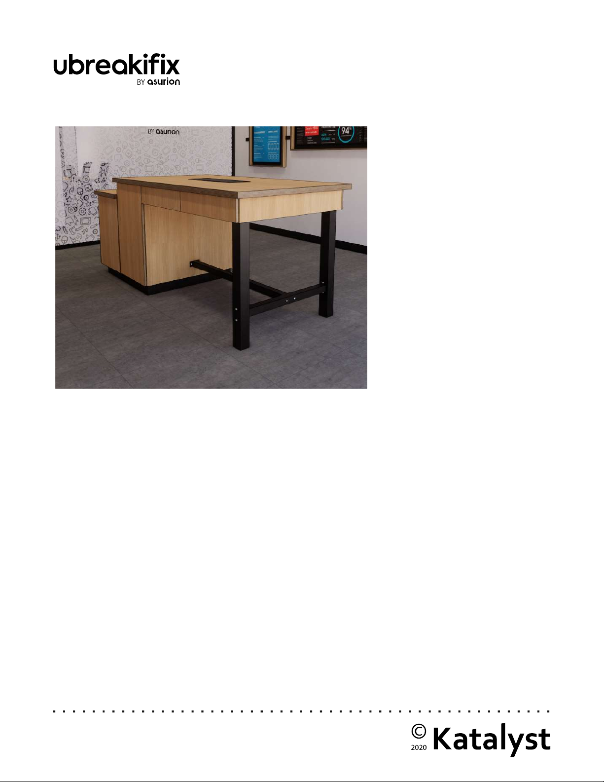
WORKBENCH INSTALLATION (8’ OR 12’ VERSION)
PARTS TO ASSEMBLE
• Toe Kick
• Short Cabinet
• Tall Cabinet
• Metal Legs (2)
• Short Cross Metal Member
• Long Cross Metal Member
• Countertop
• Drawer Assembly (Metabox)
• Drop-in Power Trough (Black Box)
HARDWARE PROVIDED
A. Workbench Small Cabinet to Tall Cabinet
B. Cabinets to Toe Kick
C. Shelf Pins
D. Steel Legs to Cross Member
E. Cross Members to Horizontal Steel
F. Horizontal Steel Beam to Tall Cabinet (Black Nut Goes Inside Cabinet)
G. Steel Legs to Drawer Cabinet
H. Metabox Cabinet to Tall Cabinet
I. Cabinet to Countertop
J. Steel Black Box to Countertop

uBreakiFix Fixture Install & Maintenance Guide 5
STEP 1
Place the toekick over the floor electrical and align in
the space. Use a screw driver to adjust the leveling
feet as necessary. The cross members should go the
long direction of the table.
STEP 2
Set the short cabinet on to half the toe kick and align
with the access openings.
STEP 3
Set the taller cabinet onto the other half of the toe
kick and align the holes to connect the cabinets
together. Use a male/female furniture bolts (A) to
connect.
STEP 4
Verify alignment of the cabinet units on the toe kick.
Then use wood screws (B) in the pre-drilled holes to
attach to the toe kick below.
STEP 5
Insert adjustable shelves (C) & access panels.
Reverse the door handles using a hand screwdriver.
ASSEMBLING THE BASE CABINETS
uBreakiFix Fixture Install & Maintenance Guide 6
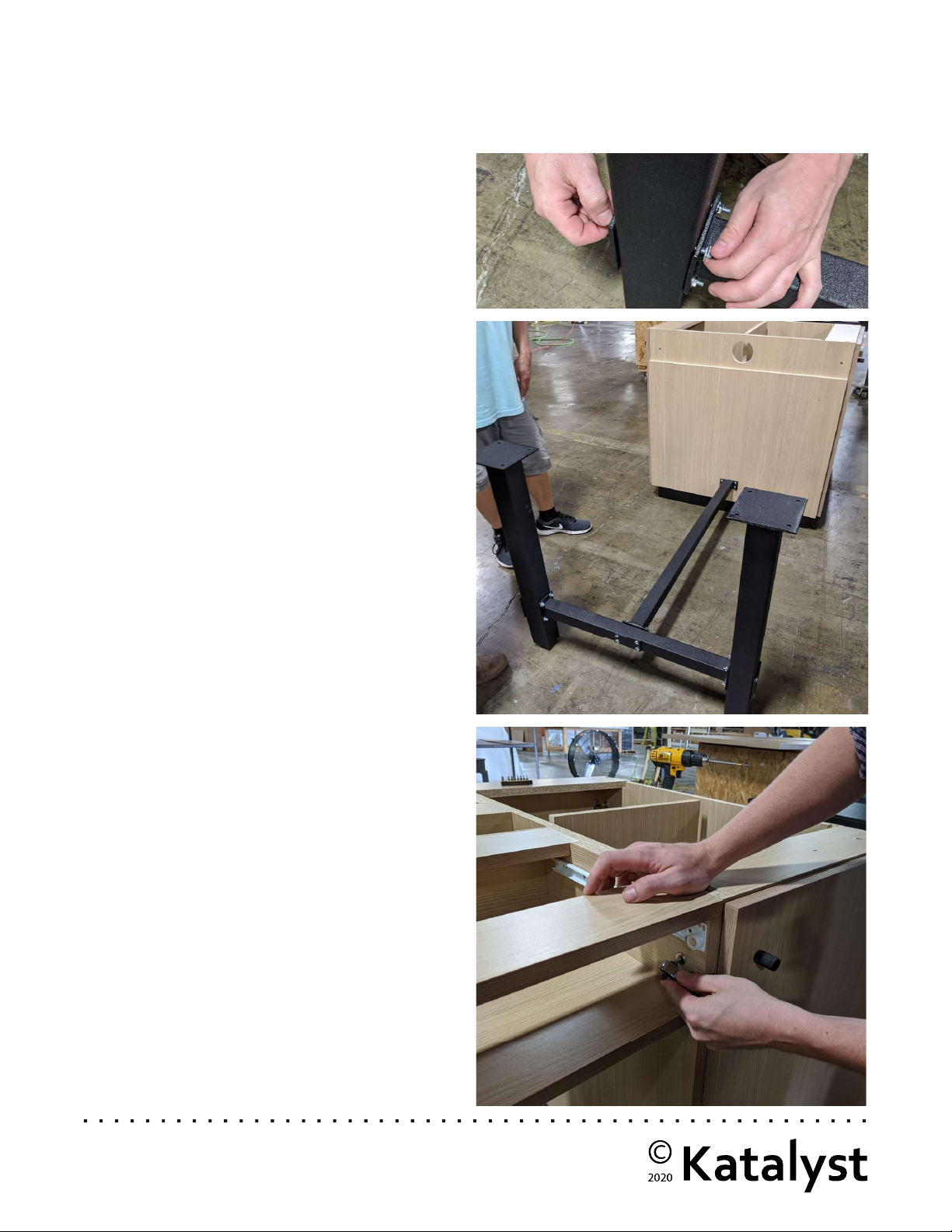
STEP 1
Locate the legs, short and long metal cross members.
STEP 2
Bolt the short cross member between the legs using
the provided carriage bolts (D).
STEP 3
Bolt the long cross member onto the middle of the
short cross member with provided carriage bolts (E).
STEP 4
Fasten the long cross member onto the tall cabinet
using the provided hardware (F). Adjust the leveling
feet in the base of the legs until level.
STEP 1
Carefully lift and set the drawer unit onto the metal
leg assembly, and the ledge of the tall cabinet.
STEP 2
Remove all drawers for access to bolt holes.
STEP 3
Attach the table legs to the drawer unit using the
provided hardware (G).
STEP 4
Align the table leg holes, and the holes in the tall
cabinet. Use provided bolts to fasten (H).
ASSEMBLING THE METAL TABLE BASE
DRAWER UNIT ASSEMBLY
uBreakiFix Fixture Install & Maintenance Guide 7
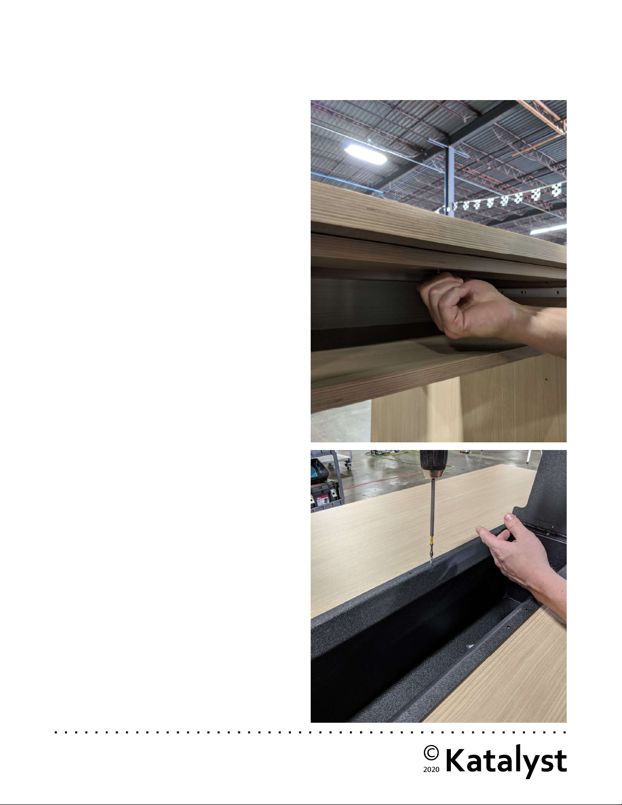
STEP 1
Place the countertop onto the drawer unit assembly
and align with bolt holes below.
STEP 2
Insert furniture bolts (I) through the top of the drawer
unit assembly into the base of the countertops. Use
allen wrench to secure.
STEP 3
Insert the drop-in power trough and secure to
countertop with provided screws (J).
STEP 4
Run power into the power trough for easy access to
phone chargers.
STEP 5
Cash drawer comes pre-installed. Use the access
hole to connect for wiring.
STEP 6
Install the receipt & label printer on the pull-out shelf
in the rear cabinet on the right. The door height is
lowered to allow easy access to those items without
the cabinet needing to be opened.
COMPLETING THE WORK BENCH ASSEMBLY
uBreakiFix Fixture Install & Maintenance Guide 8
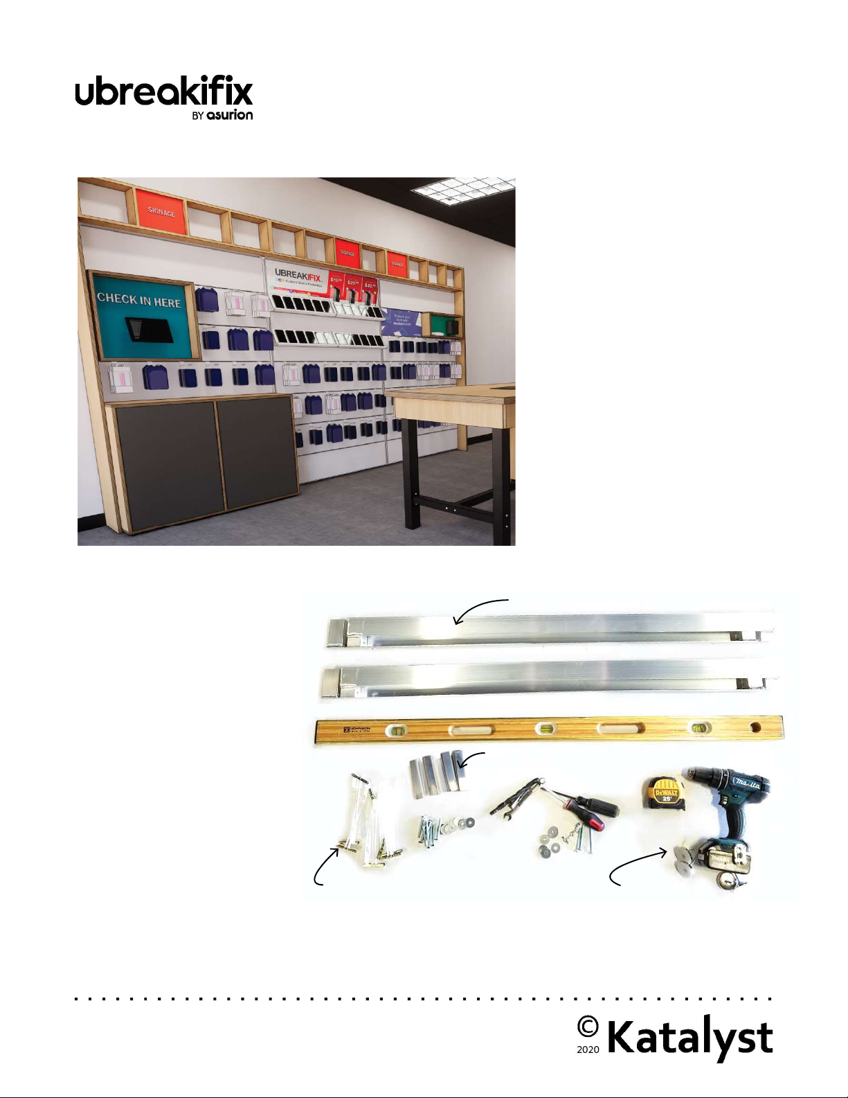
12’ TECH GALLERY ASSEMBLY
Furring Strip (2 Per 4’ Segment)
Leveling Feet
C-Channel
Snap-Toggle
PARTS TO ASSEMBLE
• (2) 4’ x 7’ K-Wall Frames
• (1) 4’ x 4’ K-Wall Frame
• Cabinet
• (3) Header Boxes
• (2) End Panels
• (6) Furring Strips
• (12) C-Channel
• (3) Bottom Wall Panels
• (15) Slat Wall Panels
HARDWARE PROVIDED
A. System Screws
B. 7’ Frame to 7’ Frame
C. Standoff Bolts
D. Tech Gallery Anchors
E. Cabinet to 4’ Frame
F. Frame to Side Panel
G. Header to Side Panels (Bolt Only)
H. Header to Header Bolt & Nut
I. Header Bolts
J. Shelf Pins

uBreakiFix Fixture Install & Maintenance Guide 9
STEP 1
Insert system screws (A) into the following wall
elements as applicable:
standard wall panels (4 per panel)
header box (2 per 4’ segment)
cabinets (4 per)
wood end plates
STEP 2
Lay the two larger K-Wall frames onto a clean and
level floor. Ensure the part of the horizontal cross-
members with holes is facing the down towards the
floor.
STEP 3
Hand screw the leveling feet into the bottom of the
K-Wall frames until snug. (2 per 4’ segment)
STEP 5
Ensuring the edges of frames are flush, add a washer
onto the frame connection bolts, and insert the bolt
through the top hole between the frames. Once
through, use a wrench to hold the bolt and secure
with a second washer and wing nut (B).
STEP 6
Repeat step 5 with one of the holes near the midpoint
of the frames, and one of the lower holes. Repeat
until both larger frames are connected.
PREPARING THE WALL SYSTEM

uBreakiFix Fixture Install & Maintenance Guide 10
STEP 7
Insert the c-channel into the furring strips. Hand
tighten the bolts (C) until lightly pressing against the
c-channel.
STEP 8
Put the furring strip with the c-channels into the
mounting channel on the K-Wall frames.
STEP 9
Insert the second bolt into the K-wall mounting
channel and hand tighten to secure.
STEP 10
Repeat steps 7-9 for the smaller, 4’ tall K-Wall frame.
INSTALL FURRING STRIPS
(2 Furring Strips Per 4’ segment)
Popular Indoor Furnishing manuals by other brands


Coaster
Coaster 4799N Assembly instructions

Stor-It-All
Stor-It-All WS39MP Assembly/installation instructions

Lexicon
Lexicon 194840161868 Assembly instruction

Next
Next AMELIA NEW 462947 Assembly instructions

impekk
impekk Manual II Assembly And Instructions

Elements
Elements Ember Nightstand CEB700NSE Assembly instructions


