PCS-N86_QG_EN_T.000.001.587_V1.1_2021.11_Final
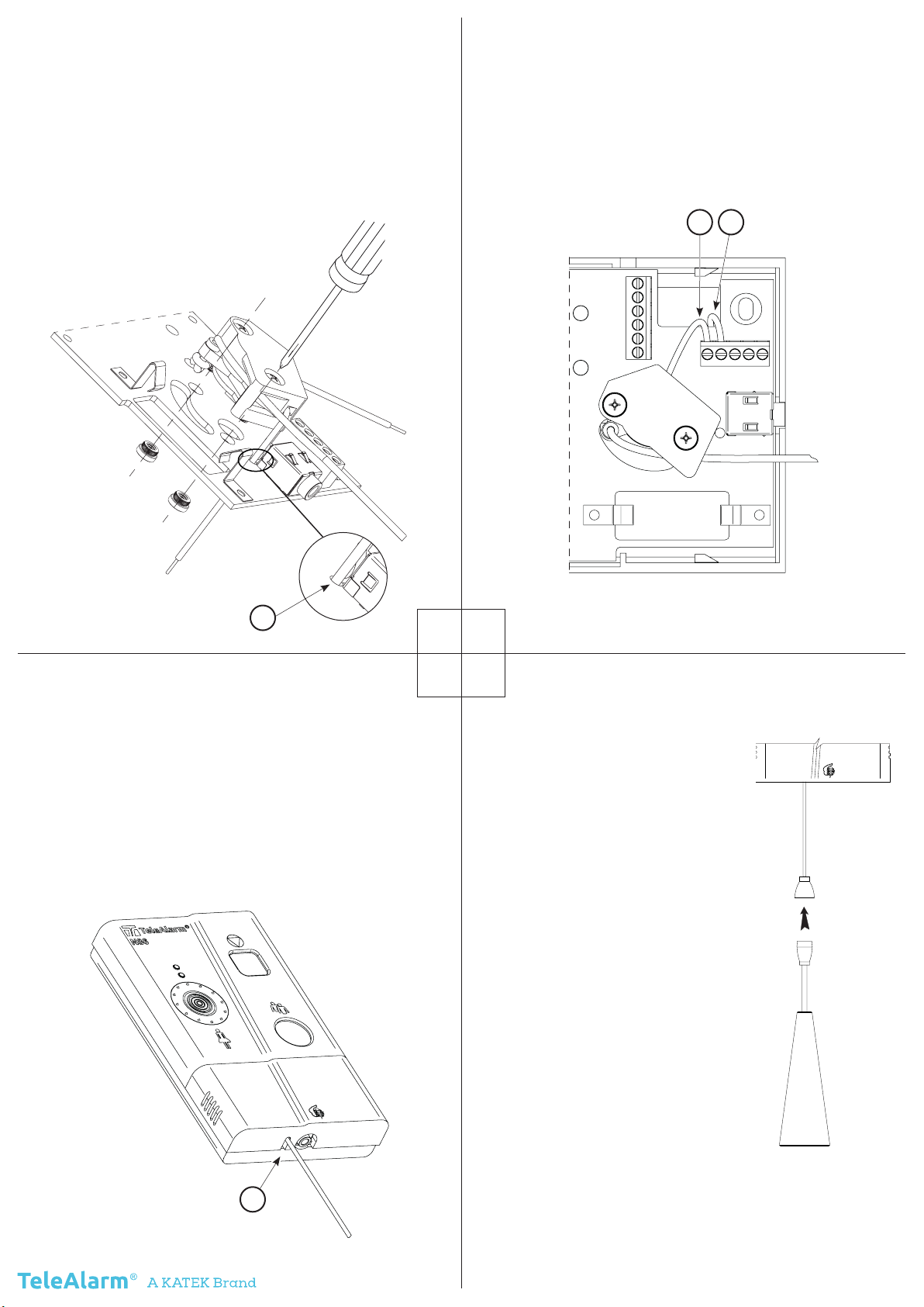
Install the switch on the printed the board:
1.
Pass the 60 mm wire through the hole in
the PCB
2.
Tighten the screws until the nuts are fully
inserted into the PCB. Recommended
torque is 0.4 Nm, max. torque is 0.6 Nm
Reinstall the PCB :
1. Reinstall the PCB
2. Connect the two wires (A and B) in
the terminal block as shown in the
picture
34
56
A B
1
Reassemble the device :
1. Replace the bottom housing
2.
Replace the 4 screws on the back of the
N86
3.
Put in place the new special batte-
ry trap, passing the cord through the
notch provided for this purpose
4.
Check that the cord slides correctly into
the notch
Finalisation:
1.
Install the N86 on the
wall
2. If needed, cut the cord
to the desired len-
gth (the cone must be
reinstalled)
3.
Plug the two break-
away parts together
4.
Test the operation: by
pulling the cord, the
N86 must send an
alarm
WARNING !
The minimum load on the
cord (to send an alarm) is
3.5 N, the maximum load
(before break-away re-
lease) is about 70 N.
3


