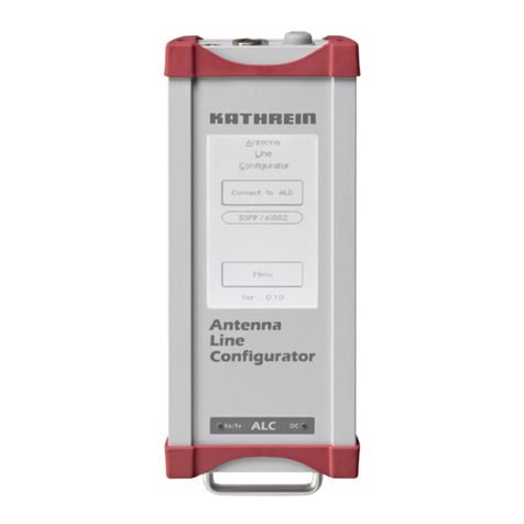
Kathrein UFG 300 User manual

UFG 300
20610082
QLCD-Display mit 4 Zeilen und je 20 Zeichen zur Anzeige
der Einstell- und Betriebs-Parameter
Q12 ergonomisch angeordnete Funktionstasten mit abrieb-
fester Bedruckung zur Eingabe der Kanalzug-Parameter
QDirekteingabe numerischer Zeichen möglich
QSpiralkabel mit 1,4 m Länge, Knickschutz und 6-poligem
Mini-DIN-Stecker zum Anschluss an die Kassetten
QUSB-Schnittstelle für Software-Update über PC
QDie Stromversorgung (5 V/100 mA) der Steuerung erfolgt
über die Kassetten
QErfüllt: EN 50083-2 und RoHS-Konformität
QAbmessungen ohne Kabel (mm): 220 x 75 x 25
QVerpackungs-Einheit/Gewicht (St./kg): 1/0,6
UFO®compact-Aufbereitungssystem
Steuerung
UFG 300 20610082
Komfortable Handsteuerung zum Programmieren der
Standard-Einstell-Parameter von UFO®compact-Kassetten.
Steuerung
Tastenfeld
USB-Buchse
DisplayMini-DIN-Stecker
Typ
Bestell-Nr. Stromaufnahme
(mA) Spannungsversorgung
(V) Gehäuseschutzart Zul. Umgebungstemperatur
(°C)
UFG 300
20610082 100 5 IP 50 nach EN 60529 +5 bis +50
1 Erklärung des Tastenfeldes
Wert vergrößern
Wert verkleinern
Nächster Parameter
Vorheriger Parameter
Nächster Kanalzug
Vorheriger Kanalzug
Untermenü
Speichern aller
Parameter-Werte
Hilfetext zum aktuell ausgewählten Parameter
Anzeige der Software-Versionen von Steuerung und
Kanalzug oder bewegen des Cursors nach links im
numerischen Eingabemodus
Editiermodus wechseln:
1. Drücken - Umschaltung in den
numerischen Eingabemodus
2. Drücken - Übernahme der Eingabe und
Verlassen des numerischen
Eingabemodus
Systemmenü:
- Spracheinstellung
- Sonderfunktionen (Kabel-NIT)
Einer Taste zugeordnete Ziffern, Buchsta-
ben und Sonderzeichen sind auf die Taste
bzw. unterhalb der Taste auf das Gehäuse
gedruckt.
2 Inbetriebnahme
QAusrichtung der Kodiernase des Mini-DIN-Steckers nach links
QEinstecken des Mini-DIN-Steckers in die mit „PRG“
gekennzeichnete Buchse des UFO®compact-Kanalzuges
QDie Stromversorgung der Steuerung erfolgt über die Kassette bzw. bei Verwendung
eines Steuerungsbus-Demultiplexers UFX 312 oder UFX 314 über diesen
936.3627/-/1109/1.7d
Hinweis:
Die aktuellste Version dieses Anwendungshinweises
finden Sie auf der Kathrein-Homepage unter
„www.kathrein.de →Service →Bedienungsanleitungen“

3 Bedienhinweise
Der durch die Tasten und aktuell ausgewählte Parameter blinkt in der Anzeige.
Die Einstellung des gewünschten Wertes erfolgt schrittweise durch die Tasten bzw. oder durch die Eingabe
numerischer Zeichen mit der Taste (siehe Abschnitt 4).
Das Anwählen bzw. das Verlassen eines Untermenüs erfolgt durch die Taste .
In der Anzeige blinkt das Symbol , wenn für den ausgewählten Parameter ein Untermenü zur Verfügung steht.
Bei Trennung der Steuerung von der UFO®compact-Kassette ohne Speichern mit der Taste werden die Einstellungen
wieder aktiv, die ursprünglich in der Kassette gespeichert waren.
Hinweis:
Die Kassetten-spezifischen Einstellanweisungen sind im Anwendungshinweis der jeweiligen UFO®compact-Kassette enthalten.
Bemerkung:
Dem Anwendungshinweis liegen Aufkleber mit Tastenerklärungen in englischer, französischer und spanischer Sprache bei.
Damit kann der in deutscher Sprache angefertigte Aufkleber auf der Rückseite des Gerätes überklebt werden.
4 Direkteingabe numerischer Parameterwerte
QDurch Drücken der Taste gelangen Sie in den Direkteingabemodus
a) dezimale Parameterwerte
QMit den Zifferntasten können die Zahlen 0... 9 an der aktuell ausgewählten Stelle eingegeben werden. Nach jeder
Zahleneingabe bewegt sich die Eingabeposition eine Stelle nach rechts
QMit der Taste wird die Eingabeposition eine Stelle nach links bewegt
b) hexadezimale Parameterwerte (gekennzeichnet mit dem Buchstaben „h“)
QMit den Tasten und können die hexadezimalen Zahlen 0 ... 9, A-F an der aktuell ausgewählten Stelle
eingegeben werden
QMit den Tasten und wird die Eingabeposition eine Stelle nach links oder rechts bewegt
QDurch erneutes Drücken der Taste wird der Direkteingabemodus verlassen und der eingegebene Wert übernommen
936.3627/-/1109/2.7d
Nachfolgendes gilt nur für numerische Eingabefelder. Durch Direkteingabe können numerische Werte stellenweise eingegeben
werden. Die aktuell ausgewählte Stelle des einzugebenden numerischen Wertes blinkt hierbei.
5 Eingabe alphanumerischer Parameterwerte
Alphanumerische Parameterwerte werden über eine virtuelle Tastatur eingegeben, die bei den entsprechenden Eingabefeldern
nach Drücken der Taste Menü im Display erscheint:
QMit den Tasten und kann die Cursor-Position verändert werden
QDie Auswahl des angewählten Zeichens erfolgt mit der Taste
QDas Löschen bereits eingegebener Zeichen erfolg mit der Taste
QDurch erneutes Drücken der Taste wird der Eingabemodus verlassen
6 Abfrage von Versionsnummern
QDrücken der Taste
QMit der Taste blättert man durch die Übersicht der Versionsnummern

936.3627/-/1109/3.7d
7 Einstellungen auf Systemebene
7.2 Einstellungen für den Aufbau der Kabel-NIT
Für den Aufbau der Kabel-Nit wird ein Steuerungsbus-Demultiplexer UFX 312 oder UFX 314 (BN 20610071) benötigt.
Der Eintrag „Kabel-Nit“ im System-Menü ist nur dann auswählbar, wenn die zentrale Steuerung an einen Demultiplexer ange-
schlossen ist (Control-Buchse).
Durch Drücken der Taste „ “ gelangt man in das System-Menü, hier können die Einstellungen zur Kabel-NIT vorgenommen
werden. Im System-Menü wird mit den Tasten „ “ bzw. „ “ „Kabel-NIT“ ausgewählt.
Mit der Taste „Untermenü“ wird das Untermenü aktiviert und durch wiederholtes Betätigen der Taste „Untermenü“ deaktiviert.
**** System ****
Kabel-NIT
Auswahl mit +/-
System-Menü Untermenü zu „Kabel-NIT“
**** Kabel-NIT ****
NIT: aus aufbauen
Network: Name ID
Mit den Tasten „ “ bzw. „ “ wird der gewünschte Parameter „aus/ein“, „aufbauen“, „Name“ oder „ID“ angewählt.
Mit der Taste „Untermenü“ wird der gewählte Parameter aktiviert und das betreffende Untermenü geöffnet.
**** System ****
Sprache einstellen
Auswahl mit +/-
System-Menü Untermenü zu „Sprache einstellen“
**** Sprache ****
Deutsch
Mit den Doppelpfeiltasten „ “ bzw. „ “ wird die zentrale Steuerung angewählt. Dies geschieht genau wie bei den
Kanalzügen, die Steuerung hat bei der Anwahl den Rang eines Kanalzuges.
7.1 Einstellung der Sprache
Durch Drücken der Taste „ “ gelangt man in das System-Menü, wo die Sprache eingestellt, die Versionsnummern abgefragt,
das System-Passwort eingestellt und die Einstellungen zur Kabel-Nit vorgenommen werden können.
Die Anleitung hierzu findet sich am Anfang der Einstellanweisung, da diese Menüs auch auf Kanalzug-Ebene
zugänglich und von Bedeutung sind.

936.3627/-/1109/4.7d
Untermenü zu „Kabel-NIT“
**** Kabel-NIT ****
NIT: aus aufbauen
Network: Name ID
Untermenü zu „Kabel-NIT“ (Anzeige bei NIT-Aufbau)
Kabel-NIT wird
aufgebaut
Bitte warten
□□□□...
A B C E D E F G H I J K L M N O P Q R
S T U V W X Y Z 0 1 2 3 4 5 6 7 8 9 _
KATHREIN WERKE KG _
Untermenü zu „Name“ Untermenü zu „ID“
Network-ID FF 01
7.2.1 Einstellung des Namens und der Netzwerk-ID der Kabel-NIT
Mit den Tasten „ “ bzw. „ “ wird der gewünschte Parameter „ein“, „aufbauen“, „Name“ oder „ID“ angewählt.
Mit der Taste „Untermenü“ wird der gewählte Parameter aktiviert und das betreffende Untermenü geöffnet.
Die Einstellung des Netzwerk-Namens erfolgt durch Hinzufügen „ “ oder Wegnehmen „ “ von Zeichen am blinkenden
Cursor in der dritten (Namens-) Zeile. Die Auswahl des hinzuzufügenden Zeichens erfolgt durch Verschieben des Cursors in
den ersten beiden Zeilen mit den Tasten „ “ bzw. „ “. Die maximale Anzahl der Zeichen ist 40.
Beim Verlassen des Menüs mit der Taste „Untermenü“ wird der eingestellte Wert übernommen.
Die Netzwerk-ID sollte nur eingestellt werden, wenn sie vom Betreiber bei der ETSI beantragt und erteilt wurde.
Der voreingestellte Wert (FF01) ist für Netze ohne besondere Netzwerk-ID vorgesehen.
Die Netzwerk-ID wird stellenweise mit den Tasten „ “ bzw. „ “ angewählt und mit den Tasten „ “ bzw. „ “ verändert.
Beim Verlassen des Menüs mit der Taste „Untermenü“ wird der eingestellte Wert übernommen.
7.2.2 Aufbau der Kabel-NIT, Ein- und Ausschalten der Kabel-NIT
Die Steuerung führt den Aufbau der Kabel-NIT komplett durch, nachdem er von Hand mit Taste „ “ oder „ “ gestartet wurde.
Die neue Kabel-NIT wird erstellt und anschließend an die Kanalzüge verschickt. Ein Abbruch des Vorgangs ist mit der Taste „ “
möglich (führt zu unten dargestellter Fehlermeldung). Während des Aufbaus läuft eine Bandanzeige in der unteren Zeile des
Displays.
Wenn die Kabel-NIT komplett ist, wird sie gespeichert und kann nun nach Bedarf ein- oder ausgeschaltet werden. Dazu im
Untermenü „Kabel-NIT“ „ein/aus“ mit den Tasten „ “ bzw. „ “ anwählen und mit den Tasten „ “ bzw. „ “ umschalten.
Untermenü zu „Kabel-NIT“
**** Kabel-NIT ****
NIT: ein aufbauen
Network: Name ID
Untermenü zu „Kabel-NIT“ (Anzeige bei Abbruch)
NIT-Fehler:
Benutzerabbruch
<Weiter: Taste>
Folgende Fehlermeldungen sind beim Aufbau der Kabel-NIT möglich:
Untermenü zu „Kabel-NIT“
NIT-Fehler
Nicht alle Kanal-
zuege eingerastet
< Weiter: Taste >
Untermenü zu „Kabel-NIT“
NIT-Fehler:
Steckvorschrift
nicht eingehalten
< Weiter: Taste >

936.3627/-/1109/5.7d
a) Aufbau mit einer Eingangsverteiler-Reihe b) Zwei Polarisationen
z.B. UFO390
z.B. Astra H
z.B. UFO 370
z.B. UFO390
z.B. UFO390
z.B. UFO390
A
z.B. Astra H
z.B. UFO390
z.B. UFO390
z.B. UFO390
z.B. UFO390
z.B. Astra V
z.B. UFO 370
z.B. UFO390
z.B. UFO390
z.B. UFO390
AB
Voraussetzung für einen erfolgreichen Aufbau der NIT:
●Die Anlage muss komplett eingestellt sein
●Alle digitalen Kanalzüge müssen in Betrieb und deren Frontends eingerastet sein
7.2.3 Zur Planung einer Anlage mit Kabel-NIT
Zur Planung einer Anlage mit eigener Kabel-NIT ist bezüglich der Position der Kassetten Folgendes zu beachten:
Fall 1: Alle verwendeten Kassetten beherrschen die Funktion der Kabel NIT.
In diesem Fall ist die Position der einzelnen Kassetten in der Anlage beliebig und nicht von Bedeutung.
Fall 2: UFO®compact-System mit gemischter Bestückung
Besitzen nicht alle verwendeten Kassetten die Fähigkeit, eine Kabel-NIT aufzubauen, muss die im Folgenden
beschriebene Steckvorschrift beachtet werden.
Steckvorschrift:
Zur Erstellung der Kabel-NIT ist es erforderlich, dass jede SAT-Ebene von mindestens einem NIT-aufbaufähigen Kanalzug
erreicht werden kann.
z.B. UFO 371/TP
z.B. UFO 371/TP
c) Zwei Eingangsverteiler-Reihen, mehrere Polarisationen (mit Option UFS 340)
A
z.B. Astra H
zu Ein
g
än
g
en A
z.B. UFO390
z.B. UFO 370
z.B. UFO390
z.B. UFO390
z.B. UFO390
z.B. UFO 370
z.B. UFO390
z.B. UFO390
z.B. UFO390
B
zu Ein
g
än
g
en A zu Ein
g
än
g
en A
z.B. Eutels. H
B
z.B. Astra
zu Ein
g
än
g
en B
B
zu Ein
g
än
g
en B
B
z.B. Eutels. V
zu Ein
g
än
g
en B
Hinweis:
Die Kabel-NIT kann nur auf Transpon-
dern eingesetzt werden, die mit einem
NIT-aufbaufähigen Kanalzug bestückt
sind.
z.B. UFO 371/TP
z.B. UFO 371/TP
Hinweis: Der NIT-Aufbau kann nicht durchgeführt werden, wenn das HF-Ausgangssignal bei einem ungenutzten Kanal-
zug eingeschaltet ist.

8.2 Programmierung der Firmware (Software-Update)
• Voraussetzungen:
a) PC/Laptop mit folgenden Systemvoraussetzungen:
• USB-Schnittstelle
• Betriebssystem Windows 2000 oder Windows XP
• Installierter USB-Treiber für UFG 300 (siehe Abschnitt 7.3)
• Administratorrechte für die Installation des USB-Treibers für UFG 300
b) USB-Kabel
c) PC-Software „Bootload.exe“ mit der Version 2.10 oder höher
• Update-Vorgang:
a) Freie USB-Schnittstelle am PC und USB-Schnittstelle der UFO®compact-Steuerung über USB-Kabel verbinden
b) USB-Treiber für UFG 300 auf dem PC installieren, sofern dies noch nicht erfolgt ist (siehe Abschnitt 7.3)
Die folgenden Schritte beziehen sich auf die Update-Software „bootload.exe“:
c) „bootload.exe“ starten
d) „Setup“ drücken
e) COM-Port aus Schritt j) in Abschnitt 7.3 auswählen
f) „File wählen“ drücken
g) Firmware „setup.bin“ auswählen
h) „Öffnen“ drücken
i) „Download“ drücken. Der Software-Update wird hierdurch gestartet
j) Der Update-Vorgang ist abgeschlossen, wenn die Fortschrittsanzeige verschwindet und die Meldung
„Starte Anwendung“ erscheint.
8 Software-Update
8.1 Allgemeines
Die Software für die UFO®compact-Steuerung besteht aus zwei Komponenten:
a) Bootloader: Software zum Austausch der Firmware
b) Firmware: Software zur Konfiguration der UFO®compact-Kanalzüge
Mit Hilfe eines PC-Programmes („bootload.exe“) kann die Firmware ausgetauscht werden.
Wichtiger Hinweis:
Für die Durchführung des Software-Updates ist keine Verbindung zur UFO®compact-Anlage notwendig.
Die Spannungsversorgung erfolgt über die USB-Schnittstelle.
936.3627/-/1109/6.7d
8.3 Installation des USB-Treibers für UFG 300
Die Installation wird am Beispiel von Windows XP gezeigt. Die Installation für Windows 2000 erfolgt entsprechend.
a) Als Windows-Benutzer mit Administratorrechten anmelden
b) Datei mit USB-Treiber (z. B. „CDM 2.00.00.zip“) in ein beliebiges Verzeichnis entpacken
c) Freie USB-Schnittstelle am PC und USB-Schnittstelle der UFO®compact-Steuerung über USB-Kabel verbinden
d) Warten, bis Windows-Assistent für die Installation neuer Hardware erscheint
e) Dialog „Verbindung mit Windows Update herstellen“
- Folgende Auswahl treffen:
„Soll eine Verbindung mit Windows Update hergestellt werden, um nach Software zu suchen?“
„Nein, diesmal nicht“
- „Weiter“ drücken

Elektronische Geräte gehören nicht in den Hausmüll, sondern müssen - gemäß Richtlinie 2002/96/EG DES EUROPÄISCHEN
PARLAMENTS UND DES RATES vom 27. Januar 2003 über Elektro- und Elektronik-Altgeräte -
fachgerecht entsorgt werden. Bitte geben Sie dieses Gerät am Ende seiner Verwendung zur Entsorgung an den dafür
vorgesehenen öffentlichen Sammelstellen ab.
Internet: www.kathrein.de
KATHREIN-Werke KG • Telefon (0 80 31) 1 84-0 • Fax (0 80 31) 1 84-3 06 • Anton-Kathrein-Straße 1 - 3 • Postfach 100 144 • D-83004 Rosenheim
936.3627/-/1109/7.7d/ZWT Technische Änderungen vorbehalten.
9 Warn- und Sicherheitshinweise
• Das LCD-Display ist bruchempfindlich und kann daher bei Herabfallen des Gerätes zerstört werden.
• Kabel nicht knicken!
• Mini-DIN-Stecker nur in UFO®compact-Kanalzüge stecken
• Gerät nicht öffnen!
f) Dialog „Auswahl der Installationsquelle“
- Folgende Auswahl treffen:
„Wie möchten Sie vorgehen?“
„Software von einer Liste oder bestimmten Quelle installieren“
- „Weiter“ drücken
g) Dialog „Such- und Installationsoptionen“
- „Diese Quellen nach dem zutreffendsten Treiber durchsuchen“ auswählen
- „Wechselmedien durchsuchen“ deaktivieren
- „Folgende Quelle ebenfalls durchsuchen“ aktivieren
- „Durchsuchen“ drücken
- Verzeichnis mit USB-Treiber aus Schritt a) auswählen
- „OK“ drücken
- „Weiter“ drücken
h) Dialog „Fertigstellen des Assistenten“
- „Fertig stellen“ drücken
i) Falls die Schritte e) bis h) bereits zwei Mal durchlaufen wurden, weiter bei Schritt j).
Ansonsten Schritte e) bis h) erneut wiederholen
Bemerkung: Der benötigte „USB Serial Port“-Treiber wird erst im zweiten Durchlauf installiert
j) Überprüfen, ob der USB-Treiber für den UFG 300 korrekt installiert wurde.
Hierzu den Geräte-Manager von Windows wie folgt starten:
- Systemsteuerung über „Start →Einstellungen →Systemsteuerung“ aufrufen
- „System“-Applet starten
- Reiter „Hardware“ auswählen
- „Geräte-Manager“ drücken
Unter den Anschlüssen „COM“ und „LPT“ muss ein Eintrag „USB Serial Port“, gefolgt von einem COM-Port, vorhanden
sein. Den COM-Port notieren, dieser wird später im Schritt e) bei der Programmierung der Firmware benötigt.
Fehlt der Eintrag, wie folgt vorgehen:
- Geräte-Manager wieder schließen
- USB-Verbindung zwischen Steuerung und PC trennen
- Einige Sekunden warten und anschließend USB-Verbindung zwischen Steuerung und PC wieder herstellen
- Geräte-Manager starten und, wie oben beschrieben, nach dem Eintrag „USB Serial Port“ suchen

UFG 300
20610082
QLCD display with 4 lines and 20 characters per line for
display of the settings and operating parameters
Q12 ergonomically arranged function buttons with rub-proof
labelling for entering the channel unit parameters
QNumeric characters can be input directly
QSpiral cable, 1.4 m long, non-kinking, 6-pin mini DIN plug
for connection to modules
QUSB interface for software-update via PC
QPower supply (5 V/100 mA) to controller via modules
QComplies with: EN 50083-2 and RoHS conformity
QDimensions without cable (mm): 220 x 75 x 25
QPacking unit/weight (pc./kg): 1/0.6
UFO®compact signal processing system
Controller
UFG 300 20610082
Intelligent manual control unit for programming the standard
setting parameters of the UFO®compact modules.
Controller
Keypad
USB port
DisplayMini DIN plug
Type
Order no. Power consumption
(mA) Power supply
(V) Housing protection
class Permissible ambient temperature
range (°C)
UFG 300
20610082 100 5 IP 50 to EN 60529 +5 to +50
1 Explanation of the keypad
Increase value
Decrease value
Next parameter
Previous parameter
Next channel unit
Previous channel unit
Sub-menu
Save all parameter
values
Help text for the currently selected parameter
Display the software versions of the controller
and channel unit, or move the cursor to the left in
numeric input mode
Changing the edit mode:
1. Press - Change into numeric input mode
2. Press - Load the input and exit numeric
input mode
System menu:
- Language setting
- Special functions (cable NIT)
The numbers, letters and special characters
assigned to a button are printed on the
button or below the button on the housing.
2 Commissioning
QSet the coding nib of the mini-DIN plug to the left
QPlug the mini-DIN connector into the UFO®compact channel
unit socket marked “PRG”
QThe controller’s power supply comes via the module or from
a UFX 312 or UFX 314 data bus demultiplexer if one is used.
936.3627/-/1109/1.7e
Note:
The most up-to-date version of these user instructions
can be found on the Kathrein homepage under
“www.kathrein.de →Service →Operating manuals”

3 Operating notes
The parameter currently selected with the buttons and flashes on the display.
The setting of the desired value is performed stepwise via the buttons and or by inputting numeric characters using the
button (see section 4).
Select or exit a sub-menu using the button.
On the display, the symbol flashes if there is a sub-menu available for the selected parameter.
If the controller is disconnected from the UFO®compact module without saving the settings by pressing the button, the
settings originally stored in the module are restored.
Note:
The module-specific setting instructions are included with the instructions for the respective UFO®compact module.
Remark:
The instructions include stickers with button explanations in English, French and Spanish.
These can be applied over the German stickers on the back of the device.
4 Direct input of numeric parameter values
QPressing the button takes you into direct input mode
a) decimal parameter values
QThe numeric keypad can be used to input the numbers 0... 9 at the currently selected position. Every time a number
is input, the input position shifts one place to the right
QPressing the button shifts the input position one place to the left
b) hexadecimal parameter values (identified with the letter “h”)
QThe and buttons can be used to input the hexadecimal numbers 0... 9, A-F at the currently selected position
QPressing the and buttons shifts the input position one place to the left or right
QPressing the button again exits direct input mode and the input value is loaded
936.3627/-/1109/2.7e
The following instructions apply to numeric input fields. Direct input can be used to input numeric values place by place.
During this, the current input position for inputting a numeric value flashes.
5 Inputting alphanumeric parameter values
Alphanumeric parameter values are input using a virtual keyboard, which appears on the display when the menu button is
pressed:
QThe and buttons allow the cursor position to be changed
QThe character is chosen using the button
QA character already inserted is deleted using the button
QPressing the again exits input mode
6 Interrogating the version numbers
QPress the button
QThe button allows you to page through the overview of the version numbers

936.3627/-/1109/3.7e
7 Settings at system level
7.2 Settings for compiling the cable NIT
A UFX 312 or UFX 314 (BN 20610071) data bus de-multiplexer is required for compiling the cable NIT.
The “Cable NIT” entry in the system menu can be selected only if the central controller is connected to a demultiplexer
(control port).
Pressing the “ ” button brings you to the system menu, where the cable NIT settings can be made. Press the “ ” and “ ”
“Cable NIT” buttons in the system menu.
Pressing the “Sub-menu” button activates the sub-menu; pressing the “Sub-menu” button again deactivates it.
**** System ****
Cable NIT
Selection with +/-
System menu “Cable NIT” sub-menu
**** Cable NIT ****
NIT: Off Compile
Network: Name ID
Press the “ ” and “ ” buttons to select the desired parameter “Off/On”, “Compile”, “Name” or “ID”.
Press the “Sub-menu” button to activate the selected parameter and open the respective sub-menu.
**** System ****
Set language
Selection with +/-
System menu “Set language” sub-menu
**** Language settings ****
English
The central controller is selected by pressing the double arrow buttons “ ” and “ ”. The procedure is exactly the same as for
the channel units; when selected the controller has the same priority as a channel unit.
7.1 Setting the language
Pressing the “ ” button brings you to the system menu, where the language can be set and the version numbers interrogated,
the system password set and the cable NIT settings made.
The instructions for this can be found at the start of the setup instructions, since these menus are accessible at the
channel unit level and relevant to it.

936.3627/-/1109/4.7e
“Cable NIT” sub-menu
**** Cable NIT ****
NIT: Off Compile
Network: Name ID
“Cable NIT” sub-menu (display during NIT compilation)
Cable NIT
being compiled
Please wait
□□□□...
A B C E D E F G H I J K L M N O P Q R
S T U V W X Y Z 0 1 2 3 4 5 6 7 8 9 _
KATHREIN WERKE KG _
“Name” sub-menu “ID” sub-menu
Network ID FF 01
7.2.1 Setting the name and the network ID for the cable NIT
Press the “ ” and “ ” buttons to select the desired parameter “on”, “Compile”, “Name” or “ID”.
Press the “Sub-menu” button to activate the selected parameter and open the respective sub-menu.
The network name is set by adding “ ” or removing “ ” characters at the flashing cursor in the third (name) line.
The character to be added is selected by using the “ ” and “ ” buttons to move the cursor within the first two lines.
The maximum number of characters is 40.
Exit the menu by pressing the “Sub-menu” button ; this saves the set value.
The network ID should only be set if the operator applied for and was granted the ID by the ETSI.
The preset value (FF01) is intended for networks without a specific network ID.
The network ID is selected digit by digit using the “ ” and “ ” buttons and is changed using the “ ” and “ ” buttons.
Exit the menu by pressing the “Sub-menu” button ; this saves the set value.
7.2.2 Compiling the cable NIT, switching the cable NIT on and off
The controller carries the NIT compilation process through to completion after it has been started manually with the “ ” or
“” button. The new cable NIT is created and then sent to the channel units. The procedure can be aborted by pressing the
“ ” button (leading to the error message shown below). A progress bar is displayed in the bottom line of the display during the
compilation process.
When the cable NIT is complete it is saved and can now be switched on and off as required. To do this, use the “ ” and “ ”
buttons to select the “Cable NIT” “on/off” sub-menu and use the “ ” and “ ” to make the change-over.
“Cable NIT” sub-menu
**** Cable NIT ****
NIT: On Compile
Network: Surname ID
“Cable NIT” sub-menu (display if aborted)
NIT error:
User abort
<Continue: key >
The following error messages may appear during cable NIT compilation:
“Cable NIT” sub-menu
NIT error
Not all channel
units registered
< Continue: key >
“Cable NIT” sub-menu
NIT error:
Insert position specifi-
cation non-compliance
< Continue: key >

936.3627/-/1109/5.7e
a) Compilation with an input distributor row b) Two polarisations
z.B. UFO390
z.B. Astra H
z.B. UFO 370
z.B. UFO390
z.B. UFO390
z.B. UFO390
A
z.B. Astra H
z.B. UFO390
z.B. UFO390
z.B. UFO390
z.B. UFO390
z.B. Astra V
z.B. UFO 370
z.B. UFO390
z.B. UFO390
z.B. UFO390
AB
The following conditions must be fulfilled to compile the NIT successfully:
●The system must be fully set up
●All digital channel units must be in operation with their front ends clicked into place
7.2.3 Planning a system with cable NIT
When planning a system with cable NIT, the following should be noted regarding the position of the modules:
Case 1: All modules in use control the functioning of the cable NIT.
In this case the position of the individual modules in the system is immaterial and irrelevant.
Case 2: UFO®compact system made up of different module types
If not all the modules in use are capable of compiling a cable NIT, the insert position specification described
below must be complied with.
Insert position specification:
For NIT compilation to function properly, each SAT level must be reached by at least one channel unit that is capable of
compiling an NIT.
c) Two input distributor rows, several polarisations (with option UFS 340)
A
z.B. Astra H
zu Ein
g
än
g
en A
z.B. UFO390
z.B. UFO 370
z.B. UFO390
z.B. UFO390
z.B. UFO390
z.B. UFO 370
z.B. UFO390
z.B. UFO390
z.B. UFO390
B
zu Ein
g
än
g
en A zu Ein
g
än
g
en A
z.B. Eutels. H
B
z.B. Astra
zu Ein
g
än
g
en B
B
zu Ein
g
än
g
en B
B
z.B. Eutels. V
zu Ein
g
än
g
en B
Note:
The cable NIT can be used only on
transponders that are fitted with an
NIT-compilation-capable channel unit.
Note: The NIT compilation cannot be performed if the HF output signal is switched on at an unused channel unit.
e.g. UFO 371/TP
e.g. UFO 371/TP
e.g. UFO 390
e.g. UFO 390
e.g. UFO 390
e.g. UFO 390
e.g. UFO 390
e.g. UFO 390
e.g. UFO 390
e.g. UFO 390
e.g. UFO 390
e.g. UFO 390
e.g. UFO 390
e.g. Astra H e.g. Astra H e.g. Astra V
e.g. UFO 371/TP
e.g. UFO 371/TP
e.g. UFO 390
e.g. UFO 390
e.g. UFO 390
e.g. UFO 390
e.g. UFO 390
e.g. UFO 390
e.g. UFO 390
e.g. Astra H
e.g. Astra
e.g. Eutels. H
e.g. Eutels. V
to inputs A to inputs A to inputs A
to inputs B to inputs B to inputs B

8.2 Programming the firmware (software update)
• Preconditions:
a) PC/laptop with the following system requirements:
• USB port
• Operating system Windows 2000 or Windows XP
• Installed USB driver for UFG 300 (see section 7.3)
• Administrator rights for installation of the USB driver for UFG 300
b) USB cable
c) PC software “Bootload.exe” with version 2.10 or higher
• Update procedure:
a) Use the USB cable to connect the free USB interface on the PC to the USB interface on the UFO®compact controller
b) Install the USB driver for UFG 300 on the PC, if this has not previously been done (see section 7.3)
The following steps refer to the Windows update software “bootload.exe”:
c) Start “bootload.exe”
d) Press “setup”
e) Select the COM port chosen in step j) in section 7.3
f) Press “Select file”
g) Select firmware “setup.bin”
h) Press “Open”
i) Press “Download”. This starts the software update
j) The update procedure is completed when the progress display disappears and the message “Start application” appears.
8 Software Update
8.1 General Information
The software for the UFO®compact controller consists of two components:
a) Bootloader: software for exchanging the firmware
b) Firmware: software for configuration of UFO®compact channel units
The firmware can be exchanged using a PC programme (“bootload.exe”).
Important note:
No connection to the UFO®compact system is necessary to perform a software update.
Power is provided by the USB interface.
936.3627/-/1109/6.7e
8.3 Installation of the USB driver for the UFG 300
Installation under Windows XP is shown as an example. Installation under Windows 2000 is similar.
a) Log in as a Windows user with administrator rights
b) Unzip the file with the USB driver (e.g. “CDM 2.00.00.zip”) into a suitable directory
c) Use the USB cable to connect the free USB interface on the PC to the USB interface on the UFO®compact controller
d) Wait until the Windows wizard for installation of new hardware appears
e) Open the dialogue “Create connection with Windows Update”
- Select the following choices:
“Should a connection with Windows Update be created to search for software?”
“No, no this time”
- Press “Continue”

Electronic equipment is not household waste - it must be disposed of properly in accordance with Directive 2002/96/EC OF
THE EUROPEAN PARLIAMENT AND THE COUNCIL dated 27th January 2003 on waste electrical and electronic equipment
(WEEE). At the end of its service life, take this device for disposal at a designated public collection point.
Internet: www.kathrein.de
KATHREIN-Werke KG • phone +49 8031 184-0 • Fax +49 8031 184-306 • Anton-Kathrein-Straße 1 - 3 • P.O. Box 100 144 • 83004 Rosenheim GERMANY
936.3627/-/1109/7.7e/ZWT Technical data subject to change.
9 Warning and safety notes
• The LCD display is fragile and can be damaged if the unit is dropped.
• Do not kink the cable!
• Plug the mini DIN-plug only into UFO®compact channel units
• Do not open the unit!
f) Dialogue “Selection of the Installation Source”
- Select the following choices:
“How do you wish to proceed?”
“Install software from a list or from a specific source”
- Press “Continue”
g) Dialogue “Search and Installation Options”
- Select “Search these sources for the most appropriate driver”
- Deactivate “Search interchangeable media”
- Activate “Search the following source also”
- Press “Search”
- Select the directory holding the USB driver from step a)
- Press “OK”
- Press “Continue”
h) Dialogue “Finish the Wizard”
- Press “Finish”
i) If steps e) to h) have already been run through twice, continue with step j).
Otherwise repeat steps e) to h) once again
Note: The required “USB Serial Port” driver will not be installed until the second pass
j) Check that the USB driver for the UFG 300 has been correctly installed.
This is done by starting the Windows Device Manager as follows:
- Call up the Control Panel by “Start →Settings →Control Panel”
- Start the “System” applet
- Select the “Hardware” tab
- Press “Device Manager”
An entry “USB Serial Port” must appear under both “COM” and “LPT” connections, followed by the name of a COM Port.
Make a note of the COM Port, since you will need to enter it later in step e) when programming the firmware.
If no entries are shown:
- Close the Device Manager again
- Break the USB connection between the controller and the PC
- Wait a few seconds and then re-establish the USB connection between the controller and the PC
- Start the Device Manager and, as described above, once again search for the “USB Serial Port” entry

UFG 300
20610082
QEcran LCD avec 4 lignes de 20 caractères pour l’affichage
des paramètres de réglage et de fonctionnement
Q12 touches de fonction disposées de manière ergonomique
avec relief résistant à l'usure pour la saisie des
paramètres de la voie de traitement
QPossibilité de saisie directe de caractères numériques
QCâble spirale de longueur 1,4 m, protection contre le pliage
et fiche mini DIN 6 pôles pour le raccordement aux modules
QPort USB pour la mise à jour du logiciel via PC
QAlimentation électrique (5 V/100 mA) de la commande par le
biais des modules
QConforme à : EN 50083-2 et RoHS
QDimensions sans câble (mm) : 220 x 75 x 25
QUnité d’emballage/Poids (u./kg) : 1/0,6
Système de traitement UFO®compact
Commande
UFG 300 20610082
Commande manuelle conviviale pour la programmation des
paramètres de réglage standards des modules UFO®compact.
Commande
Clavier
Prise USB
EcranFiche mini DIN
Type
Référence Consommation de
courant (mA) Alimentation en tension
(V) Type de protection
du boîtier Température ambiante
admissible (°C)
UFG 300
20610082 100 5 IP 50 selon EN 60529 +5 à +50
1 Description du clavier
Augmenter la valeur
Diminuer la valeur
Paramètre suivant
Paramètre précédent
Voie de traitement
suivante
Voie de traitement
précédente
Sous-menu
Enregistrer toutes
les valeurs de
paramètres
Texte d’aide sur le paramètre sélectionné
Affichage des versions du logiciel de la commande
et de la voie de traitement ou déplacement du
curseur vers la gauche dans le mode de saisie
numérique
Changer le mode d’édition :
1ère pression - passage au mode de
saisie numérique
2ème pression - validation de la saisie et
sortie du mode de saisie
numérique
Menu Système :
- Réglage de la langue
- Fonctions spéciales
(table NIT câble)
Les chiffres, les lettres et les caractères
spéciaux affectés à une touche sont
imprimés sur ou en dessous de la touche
sur le boîtier.
2 Mise en service
QOrienter l’ergot de la fiche mini DIN vers la gauche
QIntroduire la fiche mini DIN dans la prise signalée « PRG »
de la voie de traitement UFO®compact
QL’alimentation électrique de la commande se fait par le biais du module ou, si un démultiplexeur
pour bus de commande UFX 312 ou UFX 314 est utilisé, via celui-ci
936.3627/-/1109/1.7f
Remarque :
Vous trouverez la version la plus récente de ces
instructions d’utilisation sur le site Kathrein, sous
« www.kathrein.de →Service →Bedienungsanleitungen
(Notices d’utilisation) »

3 Consignes d’utilisation
Le paramètre sélectionné au moyen des touches et clignote sur l’écran.
Le réglage de la valeur souhaitée se fait graduellement en appuyant sur les touches ou ou en saisissant les caractères
numériques avec la touche (voir section 4).
Pour sélectionner ou quitter un sous-menu, appuyer sur la touche .
Le symbole clignote sur l’écran lorsqu'un sous-menu est disponible pour le paramètre sélectionné.
Si la commande est séparée du module UFO®compact sans enregistrement avec la touche , les réglages initialement
enregistrés dans le module sont réactivés.
Remarque :
Les consignes de réglage des modules figurent dans les instructions d’utilisation du module UFO®compact correspondant.
Observation :
Une étiquette adhésive avec des explications des touches en anglais, français et espagnol est fournie avec les instructions
d'utilisation. Cette étiquette peut être collée sur l’étiquette en allemand placée à l’arrière de l’appareil.
4 Saisie directe de valeurs de paramètres numériques
QAppuyer sur la touche pour accéder au mode de saisie directe
a) valeurs de paramètres décimales
QAvec les touches numériques, les chiffres 0 à 9 peuvent être saisis à la position sélectionnée. Après chaque saisie
d’un chiffre, la position de saisie se décale vers la droite
QAvec la touche , la position de saisie se décale vers la gauche
b) valeurs de paramètres hexadécimales (signalées par la lettre « h »)
QAvec les touches et , les chiffres hexadécimaux 0 à 9, A-F peuvent être saisis à la position sélectionnée
QAvec les touches et , la position de saisie se décale à gauche ou à droite
QAppuyer de nouveau sur la touche pour quitter le mode de saisie directe et enregistrer la valeur saisie
936.3627/-/1109/2.7f
L’information suivante concerne uniquement les champs de saisie numériques. Les valeurs numériques peuvent être saisies
l’une après l’autre par saisie directe. La position sélectionnée pour la valeur numérique à saisir clignote.
5 Saisie de valeurs de paramètres alphanumériques
Les valeurs de paramètres alphanumériques sont saisies à l’aide d’un clavier virtuel qui s’affiche sur l’écran dans les champs de
saisie correspondants lorsque la touche Menu a été actionnée :
QUtiliser les touches et pour déplacer le curseur
QLa sélection du caractère choisi se fait avec la touche
QLa suppression de caractères déjà saisis se fait avec la touche
QAppuyer une nouvelle fois sur la touche pour quitter le mode de saisie
6 Consultation des numéros de version
QAppuyer sur la touche
QAvec la touche , faire défiler la liste des numéros de version

936.3627/-/1109/3.7f
7 Réglages au niveau du système
7.2 Réglages pour l’établissement de la table NIT câble
Pour l’établissement de la table NIT câble, il est nécessaire de disposer d’un démultiplexeur de bus de commande UFX 312 ou
UFX 314 (BN 20610071).
L’option « Table NIT câble » du menu Système ne peut être sélectionnée que si la commande centrale est raccordée à un
démultiplexeur (prise Control).
Appuyer sur la touche « » pour accéder au menu Système. Là, la table NIT câble peut être réglée. Sélectionner dans le
menu Système « Table NIT câble » avec les touches « » ou « ».
La touche « Sous-menu » permet d’activer le sous-menu et de le désactiver par un nouvel actionnement.
**** Système ****
Table NIT câble
Sélection avec +/-
Menu Système Sous-menu de « Table NIT câble »
**** Table NIT câble ****
NIT : arrêt établir
Réseau : Nom ID
Sélectionner avec les touches « » ou « » le paramètre « arrêt/marche », « établir », « Nom » ou « ID ».
La touche « Sous-menu » permet d’activer le paramètre choisi et d’ouvrir le sous-menu correspondant.
**** Système ****
Réglage de la langue
Sélection avec +/-
Menu Système Sous-menu de « Réglage de la langue »
**** Langue ****
Français
Sélectionner la commande centrale avec les flèches doubles « » ou « ». La procédure est identique à celle pour les
voies de traitement. La commande possède lors de la sélection le rang d’une voie de traitement.
7.1 Réglage de la langue
Appuyer sur la touche « » pour accéder au menu Système. Celui-ci permet de régler la langue, de consulter les numéros
de version, de régler le mot de passe système et d’effectuer les réglages pour la table NIT câble.
Vous trouverez les instructions correspondantes au début des consignes de réglage car ces menus sont également
accessibles au niveau des voies de traitement et sont importants.

936.3627/-/1109/4.7f
Sous-menu de « Table NIT câble »
**** Table NIT câble ****
NIT : arrêt établir
Réseau : Nom ID
Sous-menu de « Table NIT câble »
(affichage pendant l’établissement de la table NIT)
Table NIT câble
établie
Veuillez patienter
□□□□...
A B C E D E F G H I J K L M N O P Q R
S T U V W X Y Z 0 1 2 3 4 5 6 7 8 9 _
KATHREIN-Werke KG _
Sous-menu de « Nom » Sous-menu de « ID »
ID réseau FF 01
7.2.1 Réglage du nom de l’identifiant réseau de la table NIT câble
Sélectionner avec les touches « » et « » le paramètre souhaité « marche », « établir », « Nom » ou « ID ».
La touche « Sous-menu » permet d’activer le paramètre choisi et d’ouvrir le sous-menu correspondant.
Le réglage du nom de réseau s’effectue en insérant « » ou supprimant « » des caractères au niveau du curseur
clignotant dans la troisième ligne (nom). La sélection du caractère à insérer s’effectue en déplaçant le curseur dans les deux
premières lignes avec les touches « » ou « ». Le nombre maximal de caractères est de 40.
Lors de la fermeture du menu avec la touche « Sous-menu » , la valeur est enregistrée.
L’ID réseau ne doit être réglée que si elle a été requise auprès de l’ETSI et reçue par l’opérateur.
La valeur prédéfinie (FF01) est prévue pour des réseaux sans ID réseau particulier.
L’identifiant réseau est sélectionné chiffre par chiffre avec les touches « » ou « » et modifié avec les touches « » ou
« ». Lors de la fermeture du menu avec la touche « Sous-menu » , la valeur est enregistrée.
7.2.2 Etablissement de la table NIT câble, activation et désactivation de la table NIT câble
La commande effectue entièrement l’établissement de la table NIT câble après que l’opération a été lancée manuellement
avec la touche « » ou « ».
La nouvelle table NIT câble est établie puis envoyée aux voies de traitement. Cette procédure peut être annulée avec la touche
« » (entraîne l’apparition du message d’erreur représenté ci-dessous). Pendant l’établissement, un affichage de progression
défile dans la dernière ligne de l’écran.
Quand la table NIT câble est complète, elle est enregistrée et peut être activée/désactivée en fonction des besoins. Pour cela,
sélectionner dans le sous-menu « Table NIT câble » « marche/arrêt » avec les touches « » ou « » et basculer avec les
touches « » ou « ».
Sous-menu de « Table NIT câble »
**** Table NIT câble ****
NIT : marche établir
Réseau : Nom ID
Sous-menu de « Table NIT câble »
(affichage en cas d’annulation)
Erreur NIT :
Annulation utilisateur
<Suivant : touche >
Les messages d’erreur suivants peuvent apparaître durant l’établissement de la table NIT câble :
Sous-menu de « Table NIT câble »
Erreur NIT
Toutes les voies de
traitement ne sont pas
enclenchées
< Suivant : touche >
Sous-menu de « Table NIT câble »
Erreur NIT :
Instruction de
connexion non respectée
< Suivant : touche >

936.3627/-/1109/5.7f
a) Etablissement avec une série de
répartiteurs d’entrée b) Deux polarisations
z.B. UFO390
z.B. Astra H
z.B. UFO 370
z.B. UFO390
z.B. UFO390
z.B. UFO390
A
z.B. Astra H
z.B. UFO390
z.B. UFO390
z.B. UFO390
z.B. UFO390
z.B. Astra V
z.B. UFO 370
z.B. UFO390
z.B. UFO390
z.B. UFO390
AB
Condition pour le bon établissement de la table NIT :
●L’installation doit être entièrement réglée
●Toutes les voies de traitement numériques doivent être en service et leurs interfaces être enclenchées
7.2.3 Pour la planification d’une installation avec table NIT câble
Lors de la planification d’une installation avec table NIT câble intégrée, tenir compte des points suivants pour la position des
modules :
Cas 1 : Tous les modules utilisés supportent la fonction de la table NIT câble.
Dans ce cas, la position des différents modules dans l’installation est libre et n’a pas d’importance.
Cas 2 : Système UFO®compact avec équipement mixte
Si tous les modules utilisés ne peuvent pas établir une table NIT câble, tenir compte de la prescription de connexion
décrite ci-après.
Prescription de connexion :
Pour l’établissement de la table NIT câble, il est nécessaire que chaque niveau SAT puisse être atteint par au moins une voie de
traitement capable d’établir la table NIT câble.
c) Deux séries de répartiteurs d'entrée, plusieurs polarisations (avec option UFS 340)
A
z.B. Astra H
zu Ein
g
än
g
en A
z.B. UFO390
z.B. UFO 370
z.B. UFO390
z.B. UFO390
z.B. UFO390
z.B. UFO 370
z.B. UFO390
z.B. UFO390
z.B. UFO390
B
zu Ein
g
än
g
en A zu Ein
g
än
g
en A
z.B. Eutels. H
B
z.B. Astra
zu Ein
g
än
g
en B
B
zu Ein
g
än
g
en B
B
z.B. Eutels. V
zu Ein
g
än
g
en B
Remarque :
La table NIT câble ne peut être utilisée
que sur des transpondeurs qui sont
équipés d’une voie de traitement
capable d’établir une table NIT.
Remarque : L’établissement de la table NIT ne peut pas être effectué si le signal de sortie HF est activé pour une voie de
traitement inutilisée.
par ex. UFO 371/TP
par ex. UFO 371/TP
par ex. UFO 390
par ex. UFO 390
par ex. UFO 390
par ex. UFO 390
par ex. UFO 390
par ex. UFO 390
par ex. UFO 390
par ex. UFO 390
par ex. UFO 390
par ex. UFO 390
par ex. UFO 390
par ex. Astra H par ex. Astra H par ex. Astra V
par ex. UFO 371/TP
par ex. UFO 371/TP
par ex. UFO 390
par ex. UFO 390
par ex. UFO 390
par ex. UFO 390
par ex. UFO 390
par ex. UFO 390
par ex. UFO 390
par ex. Astra H
par ex. Astra
par ex. Eutels. H
par ex. Eutels. V
vers les entrées A vers les entrées A vers les entrées A
vers les entrées B vers les entrées B vers les entrées B

8.2 Programmation du firmware (mise à jour du logiciel)
• Conditions :
a) PC/portable avec les caractéristiques requises suivantes :
• Port USB
• Système d’exploitation Windows 2000 ou Windows XP
• Pilote USB installé pour UFG 300 (voir la section 7.3)
• Droits d’administrateur pour l’installation du pilote USB pour UFG 300
b) Câble USB
c) Logiciel PC « Bootload.exe » version 2.10 ou plus
• Procédure de mise à jour :
a) Relier un port USB libre du PC et le port USB de la commande UFO®compact à l’aide d’un câble USB
b) Installer le pilote USB pour UFG 300 sur le PC si cela n’a pas encore été fait (voir la section 7.3)
Les étapes suivantes se rapportent au logiciel de mise à jour « bootload.exe » :
c) Lancer « bootload.exe »
d) Appuyer sur « Setup »
e) Sélectionner le port COM de l’étape j) dans la section 7.3
f) Appuyer sur « Sélectionner fichier »
g) Sélectionner « setup.bin » du firmware
h) Appuyer sur « Ouvrir »
i) Appuyer sur « Download ». Cette action lance la mise à jour du logiciel
j) La mise a jour est terminée lorsque la barre de progression disparaît et que le message « Lancer l’application » apparaît
8 Mise à jour du logiciel
8.1 Généralités
Le logiciel pour la commande UFO®compact se compose de deux éléments :
a) Bootloader : Logiciel pour le remplacement du firmware
b) Firmware : Logiciel pour la configuration de voies de traitement UFO®compact
Le firmware peut être remplacé à l’aide d’un programme PC (« bootload.exe »).
Remarque importante :
La mise à jour du logiciel ne nécessite pas de liaison avec l’installation UFO®compact.
La tension d’alimentation est fournie par le port USB.
936.3627/-/1109/6.7f
8.3 Installation du pilote USB pour UFG 300
L’installation est décrite à l’exemple de Windows XP. Pour Windows 2000, procéder de façon identique.
a) Ouvrir une session Windows avec les droits d’administrateur
b) Décomprimer le fichier comportant le pilote USB (par ex. « CDM 2.00.00.zip ») dans un répertoire quelconque
c) Relier un port USB libre du PC et le port USB de la commande UFO®compact à l’aide d’un câble USB
d) Attendre l’apparition de l’assistant d’installation d’un nouveau matériel de Windows
e) Dialogue « Connexion à Windows Update »
- Sélectionner :
« Autorisez-vous Windows à se connecter à Windows Update pour rechercher des mises à jour ? »
« Non, pas cette fois »
- Appuyer sur « Suivant »
Table of contents
Languages:
Other Kathrein Controllers manuals