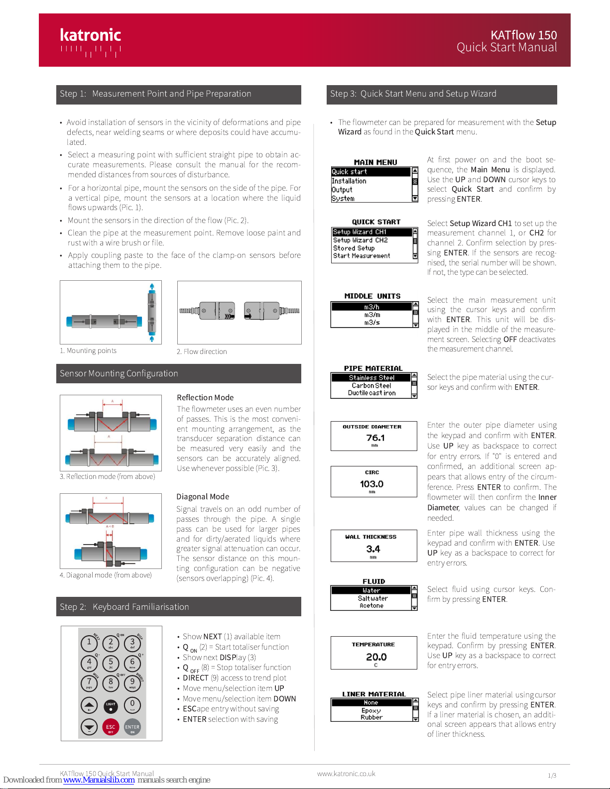
Katronic Technologies KATflow 150 Operating and maintenance instructions

1/3
KATf ow 150 Quick Start Manua www.katronic.co.uk
• Avoid insta ation of sensors in the vicinity of deformations and pipe
defects, near we ding seams or where deposits cou d have accumu-
ated.
• Se ect a measuring point with sufficient straight pipe to obtain ac-
curate measurements. P ease consu t the manua for the recom-
mended distances from sources of disturbance.
• For a horizonta pipe, mount the sensors on the side of the pipe. For
a vertica pipe, mount the sensors at a ocation where the iquid
f ows upwards (Pic. 1).
• Mount the sensors in the direction of the f ow (Pic. 2).
• C ean the pipe at the measurement point. Remove oose paint and
rust with a wire brush or fi e.
• App y coup ing paste to the face of the c amp-on sensors before
attaching them to the pipe.
Se ect
Setup Wizard CH1
to set up the
measurement channe 1, or
CH2
for
channe 2. Confirm se ection by pres-
sing
ENTER
. If the sensors are recog-
nised, the seria number wi be shown.
Ifnot, the type can be se ected.
1. Mounting points 2. F ow direction
Sensor Moun ing Configura ion
Reflectio Mode
The f owmeter uses an even number
of passes. This is the most conveni-
ent mounting arrangement, as the
transducer separation distance can
be measured very easi y and the
sensors can be accurate y a igned.
Use whenever possib e (Pic. 3).
3. Ref ection mode (from above)
Diago al Mode
Signa trave s on an odd number of
passes through the pipe. A sing e
pass can be used for arger pipes
and for dirty/aerated iquids where
greater signa attenuation can occur.
The sensor distance on this moun-
ting configuration can be negative
(sensors over apping) (Pic. 4).
S ep 3: Quick S ar Menu and Se up Wizard
At first power on and the boot se-
quence, the
Mai Me u
is disp ayed.
Use the
UP
and
DOWN
cursor keys to
se ect
Quick Start
and confirm by
pressing
ENTER
.
Enter the f uid temperature using the
keypad. Confirm by pressing
ENTER
.
Use
UP
key as a backspace to correct
for entry errors.
Se ect f uid using cursor keys. Con-
firm by pressing
ENTER
.
Enter pipe wa thickness using the
keypad and confirm with
ENTER
. Use
UP
key as a backspace to correct for
entry errors.
Enter the outer pipe diameter using
the keypad and confirm with
ENTER
.
Use
UP
key as backspace to correct
for entry errors. If "0" is entered and
confirmed, an additiona screen ap-
pears that a ows entry of the circum-
ference. Press
ENTER
to confirm. The
f owmeter wi then confirm the
I er
Diameter
, va ues can be changed if
needed.
Se ect the pipe materia using the cur-
sor keys and confirm with
ENTER
.
Se ect the main measurement unit
using the cursor keys and confirm
with
ENTER
. This unit wi be dis-
p ayed in the midd e of the measure-
ment screen. Se ecting
OFF
deactivates
the measurement channe .
• Show
NEXT
(1) avai ab e item
•
QON
(2) = Start tota iser function
• Show next
DISP
ay (3)
•
QOFF
(8) = Stop tota iser function
•
DIRECT
(9) access to trend p ot
• Move menu/se ection item
UP
• Move menu/se ection item
DOWN
•
ESC
ape entry without saving
•
ENTER
se ection with saving
S ep 1: Measuremen Poin and Pipe Prepara ion
4. Diagona mode (from above)
• The f owmeter can be prepared for measurement with the
Setup
Wizard
as found in the
Quick Start
menu.
S ep 2: Keyboard Familiarisa ion
Se ect pipe iner materia usingcursor
keys and confirm by pressing
ENTER
.
If a iner materia is chosen, an additi-
ona screen appears that a ows entry
of iner thickness.
KATflow 150
Quick S ar Manual

Measuremen Screen
The main measurement unit is dis-
p ayed when first entering the mea-
surement screen. Press
MUX
to switch
between channe s 1 and 2. Press
NEXT
to cyc e through the three ine
disp ay, tota iser and dua measure-
ment screens.
To aliser
The tota iser is shown when in meas-
urement mode after pressing
NEXT
twice. It can a so be assigned to the
three ine disp ay, data ogger or pro-
cess outputs by se ecting a quantity
as the unit.
In ernal Da alogger
• The data ogger is reached via
Mai Me u
-
Output
. It is activated
in
Datalogger
-
I terval
by entering and confirming a non-zero
va ue and se ecting units to be recorded. Up to ten measurement
units can be se ected for ogging under
Datalogger
-
Selectio
.
• Enter an interva of "0" and confirm to disab e the ogger.
• Use the cursor keys to high ight a unit and press
ENTER
to se ect
it. Press "0" to dese ect it.
• An activated data ogger is indicated by a “document” symbo in
the top eft corner of the disp ay. On start of measurement (mea-
surement screen disp ayed) the ogger records the se ected mea-
surement units.
• A b inking “document” symbo indicates a recording data ogger.
Separation markers are set by the data ogger whenever a session
begins.
• Leave the measurement screen by pressing
ESC
to stop recording.
• The recording interva can be changed in
Datalogger
-
I terval
.
• The data ogger is c eared using
Datalogger
-
Log Erase
. Ensure
a required data has been down oaded.
• The tota iser function is started with
QON
when in measurement
mode (measurement screen disp ayed). Pressing
Q+
resets the
tota in positive f ow direction. Pressing
Q-
resets the tota in neg-
ative f ow direction. The tota iser function can be stopped
with
QOFF
.
• Pressing
QON
again wi reset the positive, negative and overa
tota iser. Change disp ays without resetting the tota iser by
pressing
DISP
or
NEXT
.
1: 1 pass (diagona mode)
2: 2 passes (ref ection mode)
3: 3 passes (diagona mode)
4: 4 passes (ref ection mode) etc.
Se ect
Start Measureme t
and con-
firm with
ENTER
to start the sensor
positioning procedure. When both
channe s have been activated, the
procedure for
CH2
fo ows the one of
CH1
.
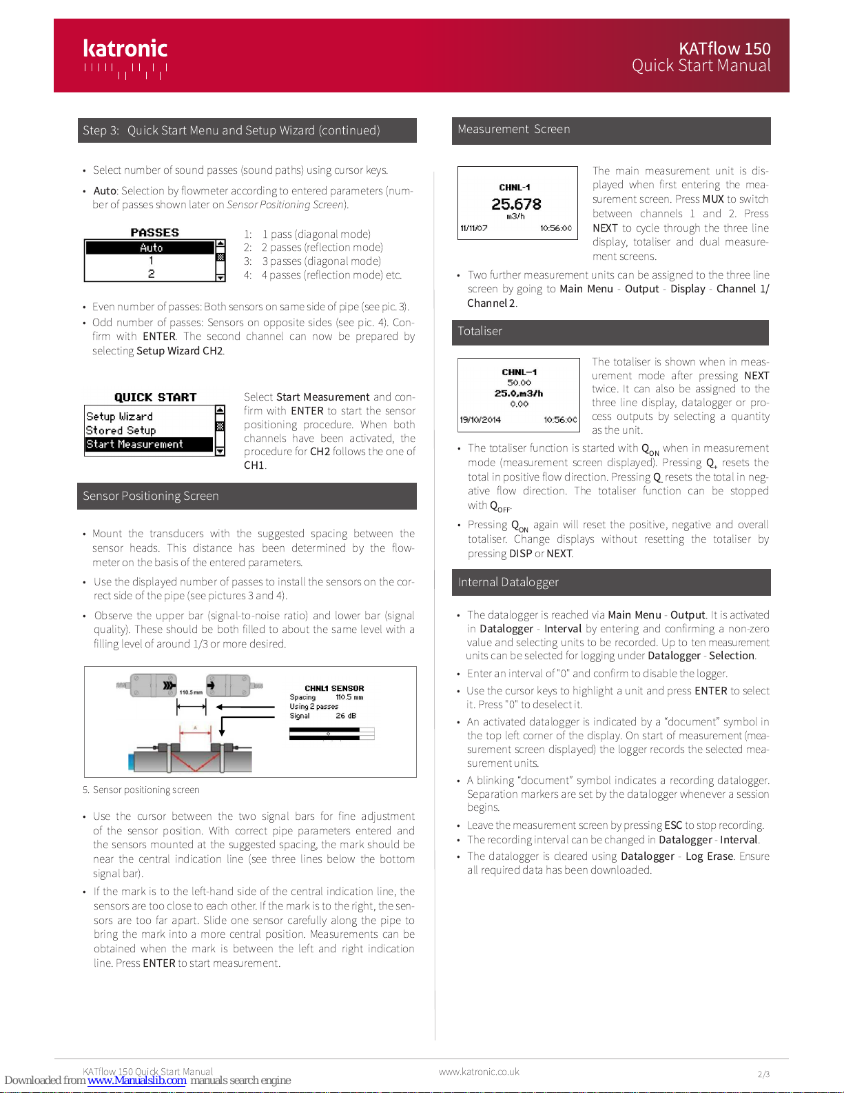
Sensor Posi ioning Screen
• Mount the transducers with the suggested spacing between the
sensor heads. This distance has been determined by the f ow-
meter on the basis of the entered parameters.
• Use the disp ayed number of passes to insta the sensors on the cor-
rect side of the pipe (see pictures 3 and 4).
• Observe the upper bar (signa -to-noise ratio) and ower bar (signa
qua ity). These shou d be both fi ed to about the same eve with a
fi ing eve of around 1/3 or more desired.
• Even number of passes: Both sensors on same side ofpipe (see pic. 3).
• Odd number of passes: Sensors on opposite sides (see pic. 4). Con-
firm with
ENTER
. The second channe can now be prepared by
se ecting
Setup Wizard CH2
.
S ep 3: Quick S ar Menu and Se up Wizard (con inued)
• Use the cursor between the two signa bars for fine adjustment
of the sensor position. With correct pipe parameters entered and
the sensors mounted at the suggested spacing, the mark shou d be
near the centra indication ine (see three ines be ow the bottom
signa bar).
• If the mark is to the eft-hand side of the centra indication ine, the
sensors are too c ose to each other. If the mark is to the right, the sen-
sors are too far apart. S ide one sensor carefu y a ong the pipe to
bring the mark into a more centra position. Measurements can be
obtained when the mark is between the eft and right indication
ine. Press
ENTER
to start measurement.
5. Sensor positioning screen
2/3
• Se ect number of sound passes (sound paths) using cursor keys.
•
Auto
: Se ection by f owmeter according to entered parameters (num-
ber of passes shown ater on
Sensor Positioning Screen
).
• Two further measurement units can be assigned to the three ine
screen by going to
Mai Me u
-
Output
-
Display
-
Cha el 1/
Cha el 2
.
www.katronic.co.uk
KATf ow 150 Quick Start Manua
KATflow 150
Quick S ar Manual

• For separate measurement of f ow and temperature se ect a
f ow unit as
Middle U it
in the
Setup Wizard
. Comp ete the
wizard and then go to
Mai Me u
-
I /Output
.
• In the
I
/
Output
menu assign the temperature input to
channe 1, and se ect
I let
or
Outlet
from the menu.
• In the
Display
menu set the
Top Li e
or
Bottom Li e
to either
Ti
or
Tout
depending on the previous se ection.
• In the
Datalogger
menu se ect either
Ti
or
Tout
from the ist
of variab es depending on the previous se ection.
• When measuring, the f owmeter wi be ogging the PT100 input
and can be viewed by pressing
1
/
NEXT
on the keypad.
• This data can a so be assigned to a process output in the
I /Output
menu fo owing the same process.
Process In/Ou pu s: Se up
• Configured in/outputs can be set up in
Mai Me u - I /Output
,
depending on which in/outputs are avai ab e. The in/output is-
ted at the top of the ist on
Slot 1
inside the connection compart-
ment, the in/output isted second from top on
Slot 2
and so on.
• After se ecting an in/output, it can be assigned to a measurement
channe . The structure of the further steps depends on the indivi-
dua type of in/output.
Process In/Ou pu s: Connec ion
• In/outputs can be connected to devices via screw termina s.
These can be found inside the connection compartment be ow
the contro pane .
• The i ustration on the eft gives an overview of the termina
assignment (Pic. 6).
• Remove the screws at the eft and right to gain access to the
compartment.
Hea Quan i y Measuremen (where specified)
• The KATf ow 150 is capab e of measuring heat f ow and heat quantity.
• To measure heat f ow, se ect a heat f ow unit (W, kW, MW) as
Middle
U it
when going through the
Setup Wizard
of the se ected measure-
ment channe .
• To measure heat quantity, se ect a heat quantity unit (J, kJ, kWh).
• On se ection of one of these units, the f owmeter requests the entry
of the specific heat capacity of the medium in [J/(g.K)]. Enter the
va ue of the f uid and confirm with
ENTER
. Comp ete the remaining
steps ofthe
Setup Wizard
.
• The temperatures at the in et and out et of the monitored system are
used to determine heat f ow and heat quantity.
• Connect the supp ied 4-wire PT100 temperature sensors to the f ow-
meter as per the i ustration be ow (Pic. 6).
6. Input/output compartment, inside termina s
• After setting up the f ow measurement channe go to
Mai Me u
-
I /Output
, in order to assign the PT100 inputs to the channe .
• Use the cursor keys to se ect
PT100 4 WIRE
and confirm with
ENTER
.
• On the next screen, use the cursor keys to se ect the f ow channe to
which the temperature input is app ied. Choose
Cha el 1
or
2
.
Se ecting
OFF
wi disab e the input. Confirm with
ENTER
.
• On the fo owing screen choose
PT100
to use the temperature meas-
ured on the pipe. To enter a fixed temperature va ue, se ect
User
and
enter the va ue.
• Define whether the PT100 sensor measures the in et or out et tempera-
ture. Use the cursor keys to se ect as appropriate and confirm with
ENTER
.
• On the next screen a temperature offset can be app ied. After confirm-
ing again with
ENTER
the meter returns to the
Mai Me u
.
• Once the setup of the first temperature input has been comp eted, re-
peat these steps for the configuration of the second input.
Tempera ure and Flow Measuremen
3/3
© Copyright Katronic Techno ogies Ltd. 2015 | Issue: QS_KF150_V42EN_1510 | A rights reserved.
KATflow 150
Quick S ar Manual
Ka ronic Technologies L d.
Tel. +44 (0)2476 714 111
E-mail info@ka ronic.co.uk
Web www.ka ronic.co.uk
Other manuals for KATflow 150
2
Other Katronic Technologies Transmitter manuals
Popular Transmitter manuals by other brands

Acromag
Acromag TT339-0700 user manual

NIVELCO
NIVELCO NIPRESS D-B00 Series User and programming manual

Ametek
Ametek 375 Series Installation and operating instructions

Rochester Gauges
Rochester Gauges 9800 Series Installation & troubleshooting guide

ACME
ACME F300 user manual

enika
enika P8 T 2 IP quick start guide