Katronic Technologies KATflow 100 User manual

Operating Instructions
Ultrasonic Flow Transmitter
KATflow 100

Tel. +31 (0)165 855 655
Internet .U-F-M.nl
E-mail mailto:[email protected]
Operating Instructions KATflow 100
Version V08E0913
Copyright © 2013
All rights reserved.
U-F-M B.V.
Argon 24
4751 XC Oud Gastel
The Netherlands

KATflo 100 Table of Contents
KATflo 100
Operating Instructions
Table of Contents
age
1 Safety instructions, legal requirements, warranty, return policy.................5
1.1 Symbols used in these operating instructions.............................................5
1.2 Safety instructions....................................................................................... 5
1.3 Warranty...................................................................................................... 6
1.4 Return policy............................................................................................... 6
1.5 Legislative requirements............................................................................. 6
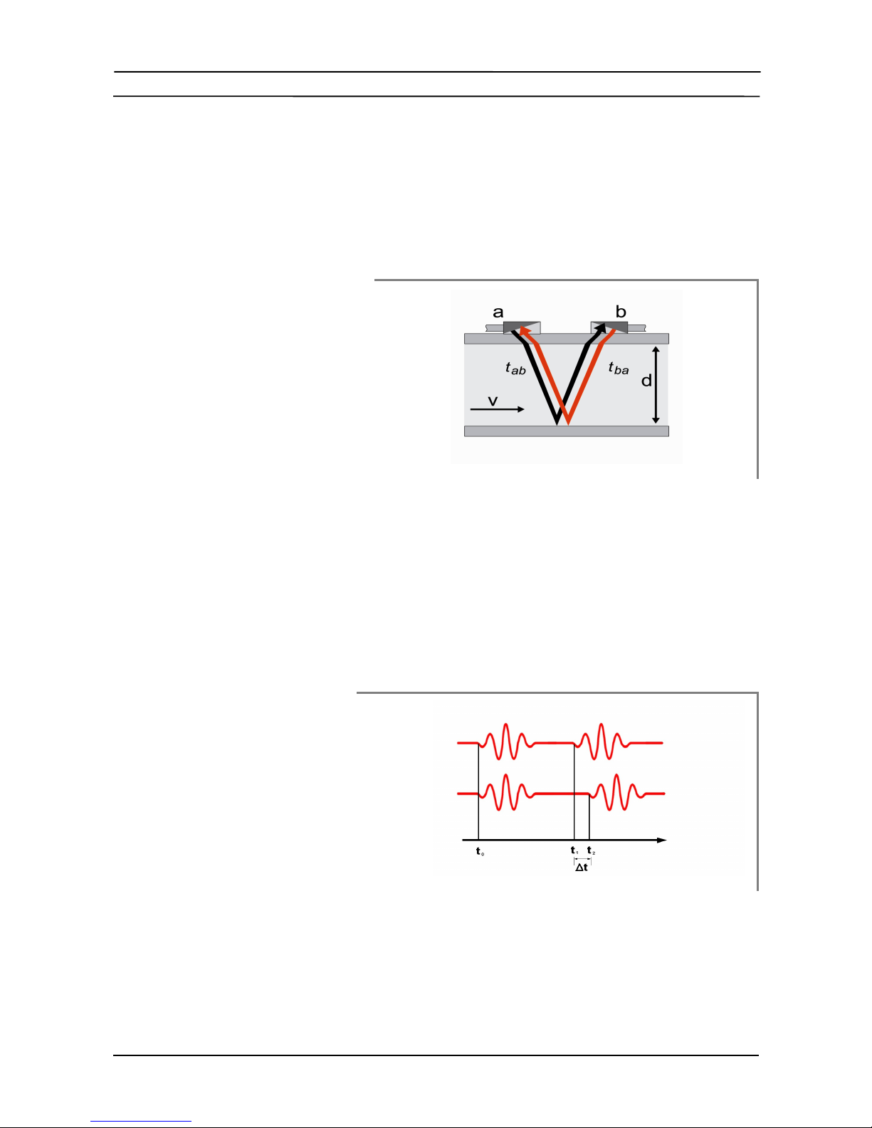
2 Introduction...................................................................................................... 7
3 Installation........................................................................................................ 8
3.1 Unpacking and storage............................................................................... 8
3.1.1 Unpacking............................................................................................ 8
3.1.2 Storage ................................................................................................ 8
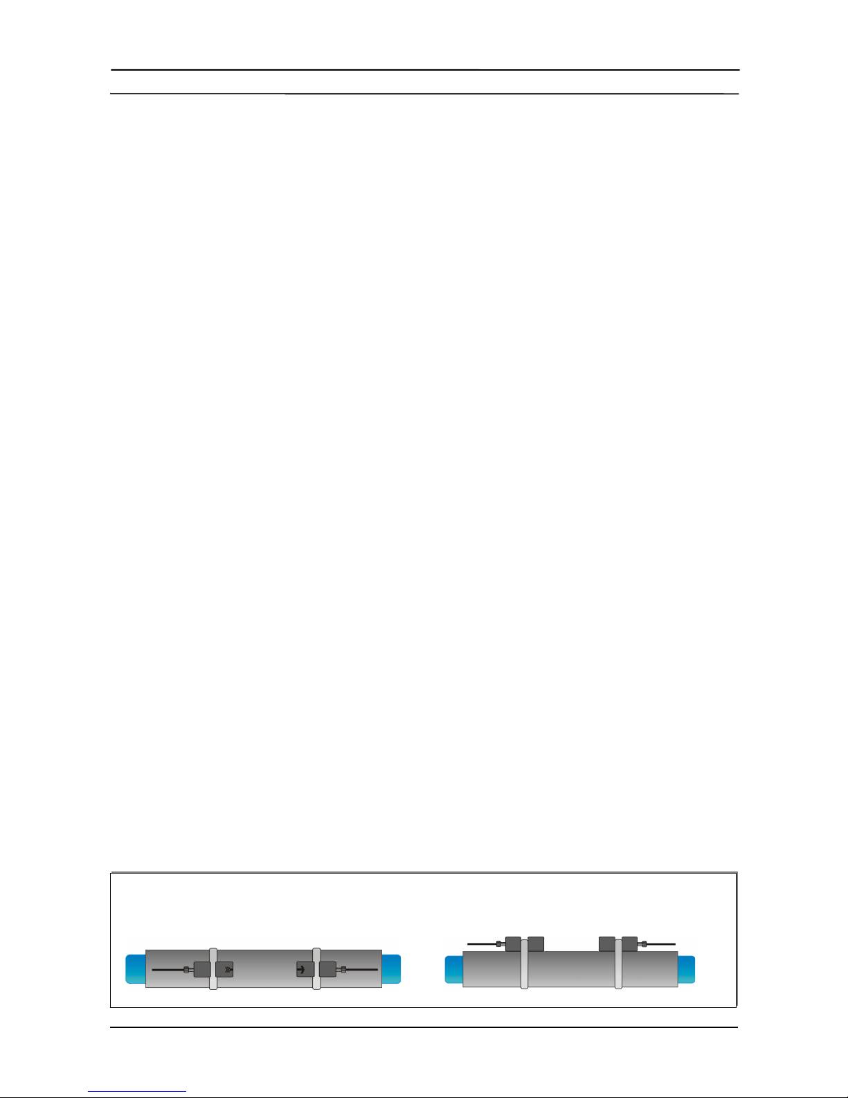
3.1.3 Identification of components................................................................. 8
3.2 Clamp-on sensor installation....................................................................... 9
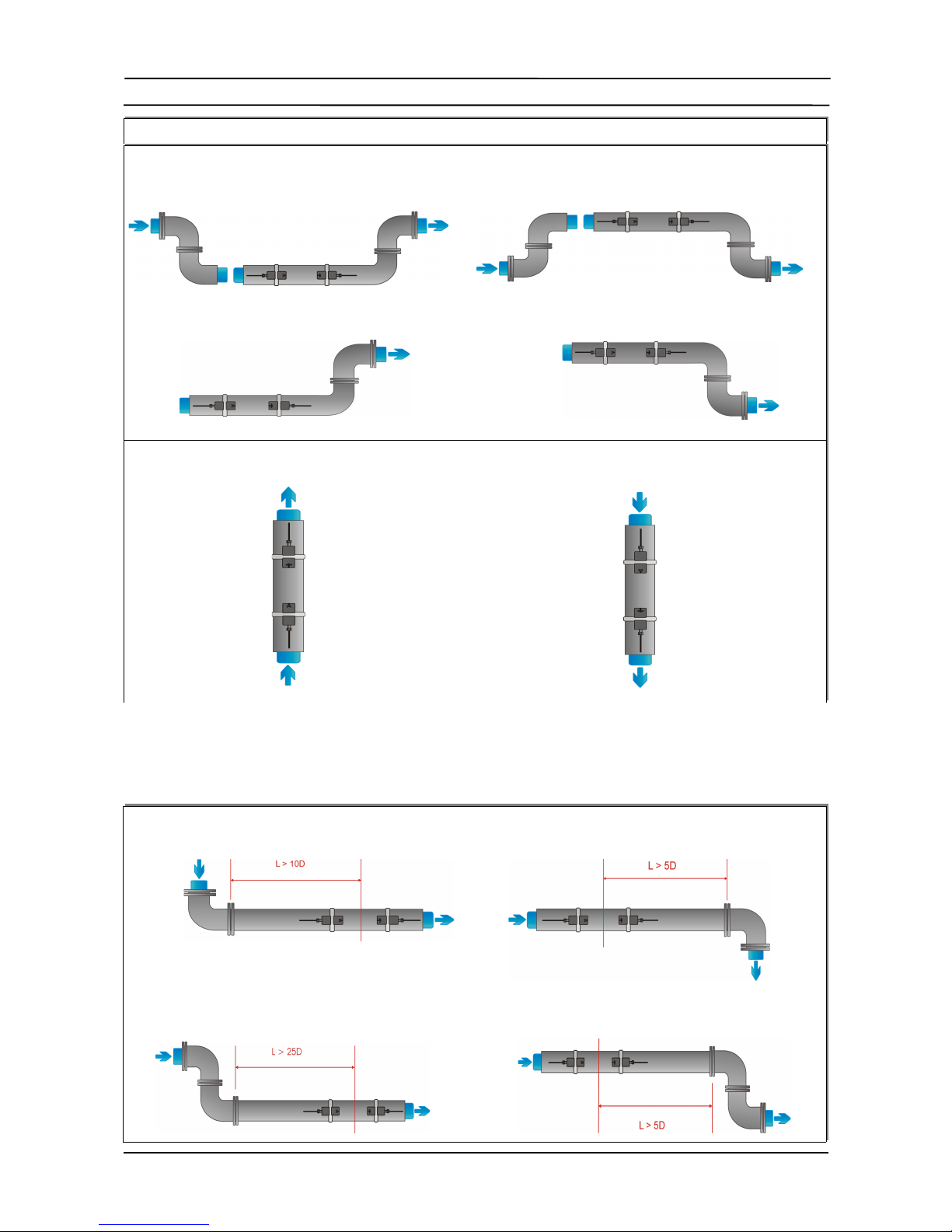
3.3 Installation location...................................................................................... 9
3.4 Pipe preparation.......................................................................................... 12
3.5 Clamp-on sensor mounting configurations and separation distance...........12
3.6 Flo meter installation.................................................................................. 13
3.6.1 Wall mounting....................................................................................... 13
3.6.2 Electrical connections........................................................................... 1
3.7 Clamp-on sensor mounting......................................................................... 16
3.7.1 Sensor pipe mounting configurations................................................... 16
3.7.2 Acoustic coupling gel............................................................................ 16
3.7.3 Correct positioning of the sensors........................................................ 17
3.7.4 Sensor mounting with tension straps....................................................17
4 Operation.......................................................................................................... 19
4.1 S itching On/Off......................................................................................... 19
4.2 Keypad and display..................................................................................... 19
4.2.1 Keypad key functions........................................................................... 19
4.2.2 Display functions.................................................................................. 21
4.3 Quick setup izard...................................................................................... 22
4.4 Measurements............................................................................................. 25
4.4.1 Main process value (PV) display.......................................................... 2
4.4.2 Diagnostic displays............................................................................... 26
4.4.3 Totalisers.............................................................................................. 26
4.4.4 Datalogger............................................................................................ 26
5 Commissioning................................................................................................ 27
5.1 Menu structure............................................................................................ 27
5.2 Diagnostics.................................................................................................. 31
5.3 Display settings........................................................................................... 31
5.4 Output configuration.................................................................................... 33
.4.1 Serial interface RS 232.........................................................................33
.4.2 Serial interface RS 48 .........................................................................33
.4.3 HART output......................................................................................... 33
.4.4 Analogue current output ...................................................................... 34
3

KATflo 100 Table of Contents
.4.4 Analogue voltage output ...................................................................... 34
.4.4 Analogue frequency output................................................................... 34
.4. Digital Open-Collector output............................................................... 3
.4.6 Digital relay output................................................................................ 3
5.5 Input configuration....................................................................................... 35
. .1 PT100 inputs........................................................................................ 3
. .2 Analogue current input 0/4 ... 20 mA.................................................... 36
5.6 Heat quantity measurement (HQM).............................................................36
5.7 Sound velocity measurement (SVM)........................................................... 36
5.8 Scope function............................................................................................. 37
6 Maintenance..................................................................................................... 38
7 Troubleshooting............................................................................................... 39
8 Technical data...................................................................................................41
9 Specification..................................................................................................... 47
10 Index................................................................................................................ 48
Appendix A......................................................................................................... 50
Appendix B......................................................................................................... 51
4

KATflo 100 1 Safety instructions, legal requirements,warranty, return policy
1 Safety instructions, legal requirements,warranty,
return policy
1.1 Symbols used in these operating instructions
Danger
This symbol represents an immediate hazardous situation hich could result in
serious injury, death or damage to the equipment. Where this symbol is sho n,
do not use the equipment further unless you have fully understood the nature of
the hazard and have taken the required precautions.
Attention
This symbol indicates important instructions hich should be respected in order to
avoid damaging or destroying the equipment. Follo the the precautions given in
these instructions to avoid the hazard. Call our service team if necessary.
Call service
Where this symbol is sho n call our service team for advice if necessary.
Note
This symbol indicates a note or detailed set-up tip.
Information point.
Operator keys are printed in bold typeface and placed in pointed brackets.
1.2 Safety instructions
●Do not install, operate or maintain this flo meter ithout reading,
understanding and follo ing these operating instructions, other ise injury
or damage may result.
●Study these operating instructions carefully before the installation of the
equipment and keep them for future reference.
●Observe all arnings, notes and instructions as marked on the packaging,
on the equipment, and detailed in the operating instructions.
●Do not use the instrument under et conditions ith the battery cover
removed or opened.
●Follo the unpacking, storage and preservation instructions to avoid
damage to the equipment.
●Install the equipment and cabling securely and safely according to the
relevant regulations.
●If the product does not operate normally, please refer to the service and
troubleshooting instructions, or contact KATRONIC for help.
5
!
<BRK>
!
+
•

KATflo 100 1 Safety instructions, legal requirements,warranty, return policy
1.3 Warranty
●Any product purchased from KATRONIC is arranted in accordance ith
the relevant product documentation and as specified in the sales contract
provided it has been used for the purpose for hich it has been designed
and operated as outlined in these operating instructions. Misuse of the
equipment ill immediately revoke any arranty given or implied.
●Responsibility for suitability and intended use of this ultrasonic flo meter
rests solely ith the user. Improper installation and operation of the
flo meter may lead to a loss of arranty.
●Please note that there are no operator-serviceable parts inside the
equipment. Any unauthorised interference ith the product ill invalidate
the arranty.
1.4 Return policy
If the unit has been diagnosed to be faulty, it can be returned to KATRONIC for
repair using the Customer Returns Note (CRN) attached to the Appendix of this
manual. KATRONIC regret that for Health & Safety reasons e cannot accept the
return of the equipment unless accompanied by the completed CRN.
1.5 Legislative requirements
The flo meter is designed to meet the safety requirements in accordance ith
sound engineering practice. It has been tested and has left the factory in a
condition in hich it is safe to operate. The equipment is in conformity ith the
statutory requirements of the EC directive and complies ith applicable regulations
and standards for electrical safety EN 61010 and electromagnetic compatibility EN
61326. A CE Declaration of Conformity has been issued in that respect, a copy of
hich can be found in the Appendix of these operating instructions.
The Waste Electrical and Electronic Equipment Directive (WEEE Directive) aims to
minimise the impact of electrical and electronic goods on the environment by
increasing re-use and recycling and by reducing the amount of WEEE going to
landfill. It seeks to achieve this by making producers responsible for financing the
collection, treatment, and recovery of aste electrical equipment, and by obliging
distributors to allo consumers to return their aste equipment free of charge.
KATRONIC offers its customers the possibility of returning unused and obsolete
equipment for correct disposal and recycling. The Dustbin Symbol indicates that
hen the last user ishes to discard this product, it must be sent to appropriate
facilities for recovery and recycling. By not discarding this product along ith other
household-type aste, the volume of aste sent to incinerators or landfills ill be
reduced and natural resources ill be conserved. Please use the Customer
Return Note (CRN) in the Appendix for return to KATRONIC.
All products manufactured by KATRONIC are compliant ith the relevant aspects
of the RoHS Directive.
6
RoHS Directive
CE marking
WEEE Directive

KATflo 100 2 Introduction
2 Introduction
The KATflo 100 is an ultrasonic flo transmitter employing clamp-on sensors for
the measurement of liquids in full, enclosed pipes. Flo measurements can be
undertaken ithout interruption of the process or interference ith the integrity of
the pipeline. The clamp-on sensors are attached to the outside of the pipes. The
KATflo 100 uses ultrasonic signals for measurement of the flo , employing the
transit-time method.
Ultrasonic signals are emitted by a transducer installed on a pipe and received by a
second transducer. These signals are emitted alternately in the direction of flo
and against it. Because the medium is flo ing, the transit time of the sound
signals propagating in the direction of flo is shorter than the transit time of the
signal propagating against the direction of flo . The transit-time difference ΔT is
measured and allo s the determination of the average flo velocity along the path
of acoustic propagation. A profile correction is then performed to obtain the
average flo velocity over the cross-sectional area of the pipe, hich is
proportional to the volumetric flo rate.
7
Illustration 1: Clamp-on ultrasonic sensor configuration
Measuring rinci le
Illustration 2: Transit-time measuring principle
Clam -on transit-
time flow transmitter

KATflo 100 3 Installation
3 Installation
3.1 Unpacking and storage
3.1.1 Unpacking
Care should be taken hen opening the box containing the flo meter, any
markings or arnings sho n on the packaging should be observed prior to
opening. The follo ing steps should then be taken:
●Unpack the flo meter in a dry area.
●The flo meter should be handled ith care and not left in an area here it
could be subject to physical shocks.
●If using a knife to remove packaging care should be taken not to damage
the flo meter or cables.
●The flo meter package and contents should be checked against the
delivery note supplied and any missing items reported immediately.
●The flo meter package and contents should be checked for signs of
damage during transport and any problems reported immediately.
●The vendor accepts no responsibility for damage or injury caused during
the unpacking of the instrumentation supplied.
●Excess packing materials should be either recycled or disposed of in a
suitable ay.
3.1.2 Storage
If storage is necessary, the flo meter and sensors should be stored:
●in a secure location,
●a ay from ater and harsh environmental conditions,
●in such a ay as to avoid damage,
●small items should be kept together in the bags provided to avoid loss.
3.1.3 Identification of components
The follo ing items are typically supplied (please refer to your delivery note for a
detailed description):
●KATflo 100 ultrasonic flo transmitter
●Clamp-on sensors (one pair for single channel operation, t o pairs for dual
channel operation)
●Sensor connection cable(s) if not direct sensor connection
●Sensor mounting accessories
●Coupling component
●Operating instructions
●Project and/or hazardous area documentation (optional)
●Calibration certificate(s) (optional)
8

KATflo 100 3 Installation
3.2 Clamp-on sensor installation
The correct selection of the sensor location is crucial for achieving reliable
measurements and high accuracy. Measurement must take place on a pipe in
hich sound can propagate (see Acoustic propagation) and in hich a rotationally
symmetrical flo profile is fully developed (see Straight pipe lengths).
The correct positioning of the transducers is an essential condition for error-free
measurements. It ensures that the sound signal ill be received under optimal
conditions and evaluated correctly. Because of the variety of applications and the
different factors influencing the measurement, there can be no standard solution for
the positioning of the transducers.
The correct position of the transducers ill be influenced by the follo ing factors:
●diameter, material, lining, all thickness and general condition of the pipe,
●the medium flo ing in the pipe,
●the presence of gas bubbles and solid particles in the medium.
Check that the temperature at the selected location is ithin the operating
temperature range of the transducers (see Specification).
After the sensor location has been selected, make sure that that supplied cable is
long enough to reach the flo transmitter mounting location. Ensure that the
temperature at the selected location is ithin the ambient operating temperature
range of the flo transmitter (see Specification).
Acoustic propagation is achieved hen the flo meter is able to receive sufficient
signal from the transmitted ultrasonic pulses. The signals are attenuated in the
pipe material, the medium and at each of the interfaces and reflections. External
and internal pipe corrosion, solid particles and gas content in the medium
contribute heavily to signal attenuation.
Sufficient straight lengths of pipe on the inlet and outlet of the measuring location
ensure an axi-symmetrical flo profile in the pipe, hich is required for good
measurement accuracy. If insufficient straight lengths of pipe are available for your
application measurements are still obtainable, but the certainty of the
measurement can be reduced.
3.3 Installation location
Select an installation location follo ing the recommendations in Table 1 and try to
avoid measuring
●in the vicinity of deformations and defects of the pipe,
●near elding seams,
●here deposits could be building up in the pipe.
For a horizontal pipe:
Select a location here the transducers can be mounted on the side of the pipe, so that the sound aves emitted by
the transducers propagate horizontally in the pipe. In this ay, the solid particles deposited on the bottom of the pipe
and the gas pockets developing at the top ill not influence the propagation of the signal.
Correct Incorrect
9
Acoustic ro agation
Straight i e lengths
+

KATflo 100 3 Installation
For a free inlet or outlet pipe section:
Select the measuring point at a location here the pipe cannot run empty.
Correct Disadvantageous
For a vertical pipe:
Select the measuring point at a location here the liquid flo s up ard to ensure that the pipe is completely filled.
Correct Incorrect
Look for a sensor installation location ith sufficient straight pipe to obtain accurate
measurements. Please refer to Table 2 as a guideline for recommended distances
from disturbance sources.
Disturbance source: 90°-elbow
Inlet Outlet
L ³ 10 D L ³ 5 D
Disturbance source: 2 x 90°-elbows in one plane
Inlet Outlet
L ³ 25 D L ³ 5 D
10
Table 1: Recommendations for sensor mounting location
+

KATflo 100 3 Installation
Disturbance source: 2 x 90°-elbows in different planes
Inlet Outlet
L ³ 40 D L ³ 5 D
Disturbance source: T-section
Inlet Outlet
L ³ 50 D L ³ 10 D
Disturbance source: diffuser
Inlet Outlet
L ³ 30 D L ³ 5 D
Disturbance source: reducer
Inlet Outlet
L ³ 10 D L ³ 5 D
Disturbance source: valve
Inlet Outlet
L ³ 40 D L ³ 10 D
Disturbance source: pump
Inlet
L ³ 50 D
11

KATflo 100 3 Installation
Table 2: Recommended distances from disturbance sources
12

KATflo 100 3 Installation
3.4 ipe preparation
●Clean dirt and dust from around the area of the pipe ork here the
sensors are to be placed.
●Remove loose paint and rust ith a ire brush or file.
Firmly bonded paint does not necessarily need to be removed provided the
flo meter diagnostics indicate sufficient signal strength.
3.5 Clamp-on sensor mounting configurations and separation
distance
The most common clamp-on sensor mounting configuration is the Reflection Mode,
sometimes kno n as V-Mode (see Illustration 3, sketch (1). Here, the ultrasonic
signal passes t ice through the medium (2 signal passes). The Reflection Mode is
the most convenient mounting method as the transducer separation distance can
be measured easily and the sensors can be accurately aligned. This method
should be used henever possible.
An alternative mounting configuration (Illustration 3, sketch (3)) is the Diagonal
mode (Z-Mode). The signals travel only once through the pipe. This method is
often used for larger pipes here greater signal attenuation might occur.
Further variation of the Reflection and the Diagonal Modes are possible by altering
the number of passes through the pipe. Any even number of passes ill require
mounting the sensors on the same side of the pipe, hile ith an odd number of
passes, the sensors must be mounted on opposite sides of the pipe. Commonly,
for very small pipes, sensor mounting configurations such as 4 passes (W-mode)
or 3 passes (N-mode) are used (Illustration 3, sketch (2)).
The transducer separation distance A is measured from the inside edges of the
sensor heads as sho n in illustration 3. It is automatically calculated by the
flo meter based on the parameter entries for pipe outside diameter, all thickness,
lining material and thickness, medium, process temperature, the sensor type and
the selected number of signal passes.
A negative separation distance A < 0 can occur for mounting configurations on
small pipes here diagonal mode operation has been selected (see Illustration 3,
sketch (3). Negative separation distances may be suggested for reflection mode
installations, but are not possible. In these cases, use diagonal mode or a larger
number of passes.
13
Illustration 3: Clamp-on sensor mounting configurations and sensor spacing
Sensor s acing
+
+
Diagonal Mode
Reflection Mode
Transducer
se aration distance

KATflo 100 3 Installation
3.6 Flowmeter installation
3.6.1 Wall mounting
The KATflo 100 is a all mounted device and can be installed using suitable
scre s and all plugs according to the follo ing dra ings.
14
Drawing 1: Outline dimensions KATflow 100 ultrasonic flowmeter
Flowmeter outline
dimensions

KATflo 100 3 Installation
Make sure that the ambient temperature is ithin the -10 ... 60 °C operating
temperature range specified for the flo meter unit.
15
Drilling aid for wall
mounting
Drawing 2: Drilling aid for wall mounting
!

KATflo 100 3 Installation
3.6.2 Electrical connections
Please note that in order to supply the unit ith MAINS POWER, the equipment
must be protected by suitably sized s itches and circuit breakers.
100 ... 240 V AC, 50/60 Hz 10 W
9 ... 36 V DC 10 W
16
Drawing 3: Electrical connection diagram for the KATflow 100 flow transmitter
!
Electrical wiring
!

KATflo 100 3 Installation
3.7 Clamp-on sensor mounting
Before the sensors can be mounted
●the installation location should have been determined,
●a sensor mounting method should be chosen,
●the flo meter must be mechanically and electrically installed,
●the sensors must be connected to the flo meter.
Depending on hich sensor mounting method is being used, the clamp on sensors
are either mounted on the same side of the pipe (Reflection Mode) or on opposite
sides of the pipe (Diagonal Mode). The sensor spacing is calculated by the
flo meter from the pipe parameters entered.
3.7.1 Sensor pipe mounting configurations
3.7.2 Acoustic coupling gel
In order to obtain acoustical contact bet een the pipe and the sensors, apply a
bead of acoustic coupling gel length ise do n the centre of the contact area of the
sensors.
17
Illustration 4: Sensor pipe mounting configurations
Illustration : Application of acoustic coupling gel
+
Sensor mounting

KATflo 100 3 Installation
3.7.3 Correct positioning of the sensors
Al ays mount the transducer pair so that the free front edges of the sensors face
each other.
There is a different engraving on the top of each transducer. The transducers are
mounted correctly if the engravings on the t o transducers form an arro . The
transducer cables should point in opposite directions.
Later, the arro , in conjunction ith the indicated measured value, ill help to
determine the direction of flo .
The sensor separation distance is automatically calculated by the flo meter based
on the parameter entries for pipe outside diameter, all thickness, lining material
and thickness, medium, process temperature, the sensor type and the selected
number of signal passes.
3.7.4 Sensor mounting with tension straps
●Cut the tension straps to the appropriate length.
●Pull at least 2 cm of the tension strap through the slot in the clamp and
bend the strap back to secure the clamp to the tension strap.
●Guide the other end of the tension strap through the groove on top of the
sensor.
●Place the sensor onto the prepared pipe section.
●Hold the clamp on the transducer ith one hand and guide the tension
strap around the pipe.
18
Illustration 7: Metallic mounting straps
Illustration 6: Correct positioning of the sensors
Correct sensor
osition
+

KATflo 100 3 Installation
●Pull the tension strap and guide the free end through the clamp so that the
clamp hooks engage. Slightly tighten the scre on the clamp.
●Mount the second sensor in the same ay.
●Press the sensors firmly to the pipe. There should be no air pockets
bet een the transducer surface and the pipe all.
●Using a measuring tape, adjust the sensor separation distance as
suggested by the flo meter. When the sensor positioning screen (Section
3.3) is displayed, the middle bar allo s fine adjustment of the sensor
location.
19
Illustration 8: Sensor mounting with tension straps and clamps

KATflo 100 4 Operation
4 Operation
4.1 Switching On/Off
The flo meter is s itched on by connecting the po er supply to the instrument.
Disconnecting the external supply s itches off the flo meter.
4.2 Keypad and display (where specified)
4.2.1 Keypad key functions (on programmer, where specified)
Key Main function Secondary function
Character entry:
1 (1 short key stroke)
, (2 short key strokes)
. (3 short key strokes)
_ (4 short key strokes)
Sho NEXT available diagnostic
screen
Character entry:
A
B
C
2
/
No function
20
Illustration 9: Keypad and display overview
Display
Keypad
Switching On/Off
KF100 rogrammer
Table 3: Menu structure
Table of contents
Other Katronic Technologies Transmitter manuals