Metek DREXELBROOK Universal IV Lite User manual

Installation and
Operating Instructions
For Assistance Call + 215-674-1234
A Leader in Level and Analytical Measurement
Universal IV™ Lite and Universal UIV™ Pro
Model Transmitters
2- Wire RF Admittance / Capacitance Level
Measurement System with HART Protocol

AMETEK Drexelbrook makes no warranty of any kind with regard to the material contained in this
manual, including, but not limited to, implied warranties or tness for a particular purpose. Drexelbrook
shall not be liable for errors contained herein or for incidental or consequential damages in connection
with the performance or use of material.
© Copyright AMETEK Drexelbrook

EDO# 02-22-123
UIV-LM
Issue # 5
205 Keith Valley Road, Horsham, PA 19044
Telephone: +1 215-674-1234
Fax: +1 215-674-2731
Website: www.drexelbrook.com
An ISO 9001 Certied Company
Universal IV™Transmitter
with HART® Protocol

This page has no content

Table of Contents
Section 1: Introduction
1.1 System Description ............................................................................................... 1
1.2 Technology ............................................................................................................ 3
1.3 Models Available ................................................................................................... 4
1.4 Probe Selection Table ........................................................................................... 6
1.5 Area Classications ............................................................................................. 6
Section 2: Installation
2.1 Unpacking ............................................................................................................. 7
2.2 Hazardous Location Installations .......................................................................... 7
2.3 Mounting the Electronic Unit ................................................................................. 8
2.4 Wiring the Electronic Unit.................................................................................... 14
2.5 Wiring the Sensing Element................................................................................ 15
2.6 Spark (Static Electricity) Protection..................................................................... 17
2.7 Surge Voltage (Lightning) Protection................................................................... 18
2.8 RFI (Radio Frequency Interference) Filters......................................................... 18
2.9 Electrostatic Filters (Desalter Filter) .................................................................... 20
Section 3: Conguration and Calibration with Drexelbrook PC Software HRTWin
3.1 Installing The USB Modem.................................................................................. 21
3.2 Install the Windows Version HRTWin Software................................................... 22
3.3 Description of Function Keys............................................................................... 23
3.4 Conguration....................................................................................................... 24
3.5 HRTWin Status Messages .................................................................................. 28
3.6 Calibration ........................................................................................................... 29
3.7 Set D/A Trim ........................................................................................................ 33
3.8 Congure Meter................................................................................................... 34
3.9 Strapping Table ................................................................................................... 34
3.10 Save/Print Entries................................................................................................ 36
3.11 Validation............................................................................................................. 37
3.12 Calibration & Conguration via Display/Keypad.................................................. 41
3.13 Status Messages................................................................................................. 46
3.14 HART Multi-Drop ................................................................................................. 49
Section 4: Conguration and Calibration with HART®Calibrator
4.1 Start-up................................................................................................................ 51
4.2 Conguration....................................................................................................... 52
4.3 Calibration ........................................................................................................... 54
4.4 D/A Trim............................................................................................................... 58
4.5 Bench Calibration Information Sheet................................................................... 60
Section 5: Troubleshooting
5.1 Identifying a Problem/Symptom .......................................................................... 62
5.2 Troubleshooting Loop Connection ...................................................................... 62
5.3 Universal IV transmitter does not communicate with HRTWin Software............. 63
5.4 Transmitter Drift Test ........................................................................................... 64
5.5 Troubleshooting Sensing Element ...................................................................... 65
5.6 Troubleshooting Coaxial Cable ........................................................................... 67
5.7 Static Electricity................................................................................................... 68
5.8 Radio Frequency Interference............................................................................. 68
5.9 Factory Assistance .............................................................................................. 69
5.10 Field Service........................................................................................................ 69
5.11 Customer Training ............................................................................................... 70
5.12 Return Equipment ............................................................................................... 70
5.13 Universal IV Troubleshooting Guide.................................................................... 71

Section 6: Specications
6.1 Transmitter Specications ................................................................................... 73
Section 7: Hazardous Location Supplementary Installation Instructions
7.1 General safety information .................................................................................. 75
7.2 The Compartment Cover..................................................................................... 76
7.3 Standards and Approvals .................................................................................... 77
Section 8: Control Drawings
8.1 ATEX / IECEX .................................................................................................... 79
8.2 FM US / FMC ...................................................................................................... 87

Section 1: Introduction
1.1 System Description
The instructions in this manual are for the AMETEK
Drexelbrook Universal IV for level measurement in liquids,
slurries, interfaces, and granulars.
Each system consists of a Universal IV two-wire, 4-20 mA
HART® electronic unit and a 700 series sensing element. A 380
series connecting cable is also supplied for connection of the
sensing element to remote electronic units.
The Universal IV system is an admittance-to-current transducer.
A change in level produces a change in admittance which results
in a change of current. It is termed a two-wire transmitter
because the same two wires that are used to power the unit also
indicate the change in level (4-20 mA).

Universal IV - Installation and Operating Instructions
2
Figure 1-1 Capacitance
Sensing Element
k
air
A
d
Ckmedia
C=kA
d
C = k A
d
Ak
air
d
C
kmedia
C=kA
d
Tank Wall
Coating
High Resistance
Little to No Resistance
Probe Insulation
Probe Rod
(More Coating is
Easier to Ignore)
R
Xc
Xc
R
Oscillator circuitry through phase shift
cancels small amounts of RF current
flow (both Resistive and Capacitive)
caused by coating
Level
Figure 1-2
RF Admittance Sensing Element
with Cote-Shield

Introduction
3
1.2 Technology
Capacitance
In a simple capacitance measurement, the capacitance increases as the
process medium covers more of the sensing element. In an insulating medium,
this is due to the increase in dielectric constant (k) from air to that of the
medium. In a conductive medium, this is due to the decreased distance from
ground as the medium provides a conductive path from the ground reference,
typically the vessel wall, to the outer surface of the sensing element
insulation.
This change in capacitance causes an imbalance in a capacitance bridge which
is detected in the circuitry and converted to an output proportional to level.
Radio Frequency (RF) Admittance
RF Admittance is the next generation. Although similar to capacitance it
adds a valuable feature, the ability to compensate for conductive coatings.
The patented Cote-Shield™ circuitry of the Universal IV Pro Model measures
resistance and capacitance separately. The level component of the sensing
element capacitance has a negligible resistance however, a conductive coating
will have a much greater resistance. The design of the circuitry also produces
signals for the resistive and capacitive RF currents of a conductive coating
to be of identical magnitude but of opposite phase. This allows the Universal
IV to subtract the effect of the coating and produce an accurate level
measurement even in the most difficult applications.
This patented Cote-Shield™ circuitry is designed into the Universal IV Pro
Model and enables the instrument to ignore the effect of buildup or material
coating on the sensing element. The sensing element is mounted in the vessel
and provides a change in RF admittance indicating the level of material.
The Cote-Shield™ circuitry prevents the transmission of RF current through
the coating on the sensing element. The only path to ground available for the
RF current is through the material being measured.
The result is an accurate measurement regardless of the amount of coating on
the sensing element. By far the most versatile technology available, it works
with all types of materials in a vast array of conditions; from cryogenics to
high temperature, and from vacuum to 10,000psi pressure.
Lite Model
The Universal IV Lite Model is the entry level RF Capacitance measurement
system for use where Cote-Shield™is not required. Lite models can be used
in non-coating and insulating coating applications. Universal IV Lite is not
recommended for use in conductive coating applications. In addition, the
Lite model has a 20-7,000 pF range that may limit the measurement span on
conductive liquids.
Pro Model
The Universal IV Pro model has the most versatility with full capabilities
of Code-Shield and measurement span of 1-45,000 pF. The Pro can handle
shorter and longer measurement spans and is compatible with a vast array of
applications.
Universal IV - Installation and Operating Instructions
4
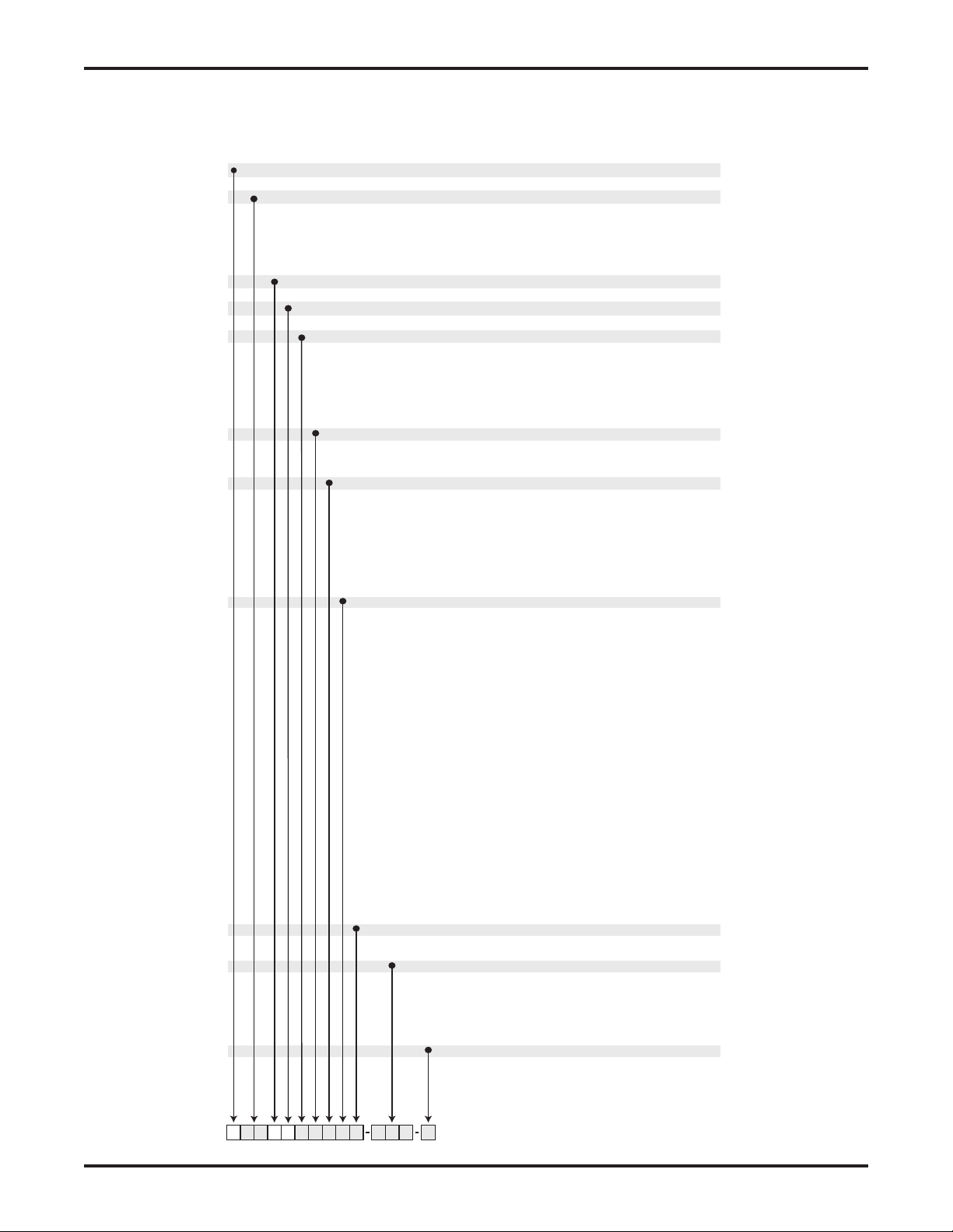
U 1 0
Future Use
0 Future Use
Technology
UUniversal IV
Digital Protocols
1HART®
Measurement Type / Frequency and Phasing
P0 Pro model: Admittance, 100 KHz, 0° Phase, 1 - 45,000 pF span
P1 Pro model: Admittance, 15 KHz, 0° Phase, 1 - 45,000 pF span
P2 Pro model: Admittance, 100 KHz, 45° Phase, 1 - 45,000 pF span
P3 Pro model: Admittance, 15 KHz, 45° Phase, 1 - 45,000 pF span
L0 Lite model: Capacitance, 100 KHz, 0 Phase, 20 - 7,000 pF span
L1 Lite model: Capacitance, 15 KHz, 0° Phase, 20 - 7,000 pF span
Approvals
0Unapproved
1FM/FMc IS
2FM/FMc XP
3ATEX ia
4ATEX d [ia]
5IECEx ia
6IECEx d [ia]
Electrical Connection
03/4" NPT without external ground lug
1M20 with external ground lug
23/4" NPT with external ground lug
Surge / Noise Suppression
0No additional filtering required
1Signal filtering RFI and Surge protection (Integral or Remote)
2Probe RFI (Remote only)
3Signal filtering and Probe RFI (Remote only)
4Probe HDSP (Heavy Duty Spark Protector) - Remote only
5Signal filtering and Probe HDSP (Remote only)
6Probe RFI and Probe HDSP (Remote only)
7Signal filtering and Probe RFI and Probe HDSP (Remote only)
DDesalter Filter (Remote only)
Integral / Remote options
0Integral configuration
1Remote configuration without cable
2Remote configuration with 10 ft General Purpose Cable
3Remote configuration with 25 ft. General Purpose Cable
4Remote configuration with 35 Ft. General Purpose Cable
5Remote configuration with 50 ft. General Purpose Cable
6Remote configuration with 75 ft. General Purpose Cable
7Remote configuration with 100 ft. General Purpose Cable
8Remote configuration with 10 ft. Triax Cable
9Remote configuration with 25 ft. Triax Cable
ARemote configuration with 35 ft. Triax Cable
BRemote configuration with 50 ft. Triax Cable
CRemote configuration with 75 ft. Triax Cable
DRemote configuration with 100 ft Triax Cable
ERemote configuration with 10 ft Hi Temp Cable
FRemote configuration with 25 ft. Hi Temp Cable
GRemote configuration with 35 ft. Hi Temp Cable
HRemote configuration with 50 ft. Hi Temp Cable
JRemote configuration with 75 ft. Hi Temp Cable
KRemote configuration with 100 ft Hi Temp Cable
LRemote configuration with 10 ft Hi Temp Composite Cable
MRemote configuration with 25 ft. Hi Temp Composite Cable
NRemote configuration with 35 ft. Hi Temp Composite Cable
ORemote configuration with 50 ft. Hi Temp Composite Cable
PRemote configuration with 75 ft. Hi Temp Composite Cable
QRemote configuration with 100 ft Hi Temp Composite Cable
ZRemote configuration with custom cable
Dual seal option
0Without Dual Seal option
1With Dual Seal option
Special Software
0None
ZSpecial Software
Sensing Element Code
### Sensing element 3-digit code (Refer to probe selection table)
000 Remote System without a probe
ZZZ Special sensing element
R00 Universal retrofit kit upgrade with all adapters for all probes
R## Retrofit kit upgrade with probe dependent adapters
R09 Remote only retrofit kit upgrade
Process gland wetted part (X)
ACarbon Steel
B316/316L SS
CHast C-276
PPFA
EMonel
UTitanium
X* Upon request
Sensing Element Selected From Table
Process connection (XX)
A0 3/4" NPT
B0 1" NPT
BA 1" 150# RF Carbon Steel
BB 1" 150# RF 316/316L Stainless Steel
CB 1" 300# RF 316/316L Stainless Steel
BD 1" 150# RF 316/316L SS TFE
C2 1 1/2" Tri-Clamp
E2 2" Tri-Clamp
FA 2" 150# RF Carbon Steel
FB 2" 150# RF 316/316L Stainless Steel
GB 2" 300# RF 316/316L Stainless Steel
FC 2" 150# RF CS TFE Face
FD 2" 150# RF 316/316L SS TFE
FE 2" 150# RF CS Inserted TFE
FH 2" 150# RF 316L SS Seal-Tyte
G0 1/2" NPT
IA 3" 150# RF Carbon Steel
IB 3" 150# RF 316/316L Stainless Steel
J2 3" Tri-Clamp
JB 3" 300# RF 316/316L Stainless Steel
KB 4" 150# RF 316/316L SS
KC 4" 150# RF CS TFE Face
KD 4" 150# RF 316/316L SS TFE
KG 4" 150# RF CS Seal-Tyte
LA 4" 300# RF Carbon Steel
LB 4" 300# RF 316/316L Stainless Steel
2B 8" 600# RF 316/316L Stainless Steel
XX* Many more options available upon request (ANSI, DIN, JIS)
Insertion Length in MM
XXXXXX Length of the probe in millimeters from process connection to the bottom of the probe
Cote-Shield™ Length in MM
XXXXXX Length of the Cote-Shield in millimeters for 3-terminal probes. Not applicable for 2-terminal probes
Inactive Length in MM
XXXXXX Length of the inactive part of the probe that is not measured.
This option is primarily used in Interface measurement and Desalters
Inactive Material
ACarbon Steel
B316/316L SS
CHast C-276
TTeflon Covered
NNot Applicable
X* Many more options are available upon request

Introduction
5
U 1 0
Future Use
0 Future Use
Technology
UUniversal IV
Digital Protocols
1HART®
Measurement Type / Frequency and Phasing
P0 Pro model: Admittance, 100 KHz, 0° Phase, 1 - 45,000 pF span
P1 Pro model: Admittance, 15 KHz, 0° Phase, 1 - 45,000 pF span
P2 Pro model: Admittance, 100 KHz, 45° Phase, 1 - 45,000 pF span
P3 Pro model: Admittance, 15 KHz, 45° Phase, 1 - 45,000 pF span
L0 Lite model: Capacitance, 100 KHz, 0 Phase, 20 - 7,000 pF span
L1 Lite model: Capacitance, 15 KHz, 0° Phase, 20 - 7,000 pF span
Approvals
0Unapproved
1FM/FMc IS
2FM/FMc XP
3ATEX ia
4ATEX d [ia]
5IECEx ia
6IECEx d [ia]
Electrical Connection
03/4" NPT without external ground lug
1M20 with external ground lug
23/4" NPT with external ground lug
Surge / Noise Suppression
0No additional filtering required
1Signal filtering RFI and Surge protection (Integral or Remote)
2Probe RFI (Remote only)
3Signal filtering and Probe RFI (Remote only)
4Probe HDSP (Heavy Duty Spark Protector) - Remote only
5Signal filtering and Probe HDSP (Remote only)
6Probe RFI and Probe HDSP (Remote only)
7Signal filtering and Probe RFI and Probe HDSP (Remote only)
DDesalter Filter (Remote only)
Integral / Remote options
0Integral configuration
1Remote configuration without cable
2Remote configuration with 10 ft General Purpose Cable
3Remote configuration with 25 ft. General Purpose Cable
4Remote configuration with 35 Ft. General Purpose Cable
5Remote configuration with 50 ft. General Purpose Cable
6Remote configuration with 75 ft. General Purpose Cable
7Remote configuration with 100 ft. General Purpose Cable
8Remote configuration with 10 ft. Triax Cable
9Remote configuration with 25 ft. Triax Cable
ARemote configuration with 35 ft. Triax Cable
BRemote configuration with 50 ft. Triax Cable
CRemote configuration with 75 ft. Triax Cable
DRemote configuration with 100 ft Triax Cable
ERemote configuration with 10 ft Hi Temp Cable
FRemote configuration with 25 ft. Hi Temp Cable
GRemote configuration with 35 ft. Hi Temp Cable
HRemote configuration with 50 ft. Hi Temp Cable
JRemote configuration with 75 ft. Hi Temp Cable
KRemote configuration with 100 ft Hi Temp Cable
LRemote configuration with 10 ft Hi Temp Composite Cable
MRemote configuration with 25 ft. Hi Temp Composite Cable
NRemote configuration with 35 ft. Hi Temp Composite Cable
ORemote configuration with 50 ft. Hi Temp Composite Cable
PRemote configuration with 75 ft. Hi Temp Composite Cable
QRemote configuration with 100 ft Hi Temp Composite Cable
ZRemote configuration with custom cable
Dual seal option
0Without Dual Seal option
1With Dual Seal option
Special Software
0None
ZSpecial Software
Sensing Element Code
### Sensing element 3-digit code (Refer to probe selection table)
000 Remote System without a probe
ZZZ Special sensing element
R00 Universal retrofit kit upgrade with all adapters for all probes
R## Retrofit kit upgrade with probe dependent adapters
R09 Remote only retrofit kit upgrade
Process gland wetted part (X)
ACarbon Steel
B316/316L SS
CHast C-276
PPFA
EMonel
UTitanium
X* Upon request
Sensing Element Selected From Table
Process connection (XX)
A0 3/4" NPT
B0 1" NPT
BA 1" 150# RF Carbon Steel
BB 1" 150# RF 316/316L Stainless Steel
CB 1" 300# RF 316/316L Stainless Steel
BD 1" 150# RF 316/316L SS TFE
C2 1 1/2" Tri-Clamp
E2 2" Tri-Clamp
FA 2" 150# RF Carbon Steel
FB 2" 150# RF 316/316L Stainless Steel
GB 2" 300# RF 316/316L Stainless Steel
FC 2" 150# RF CS TFE Face
FD 2" 150# RF 316/316L SS TFE
FE 2" 150# RF CS Inserted TFE
FH 2" 150# RF 316L SS Seal-Tyte
G0 1/2" NPT
IA 3" 150# RF Carbon Steel
IB 3" 150# RF 316/316L Stainless Steel
J2 3" Tri-Clamp
JB 3" 300# RF 316/316L Stainless Steel
KB 4" 150# RF 316/316L SS
KC 4" 150# RF CS TFE Face
KD 4" 150# RF 316/316L SS TFE
KG 4" 150# RF CS Seal-Tyte
LA 4" 300# RF Carbon Steel
LB 4" 300# RF 316/316L Stainless Steel
2B 8" 600# RF 316/316L Stainless Steel
XX* Many more options available upon request (ANSI, DIN, JIS)
Insertion Length in MM
XXXXXX Length of the probe in millimeters from process connection to the bottom of the probe
Cote-Shield™ Length in MM
XXXXXX Length of the Cote-Shield in millimeters for 3-terminal probes. Not applicable for 2-terminal probes
Inactive Length in MM
XXXXXX Length of the inactive part of the probe that is not measured.
This option is primarily used in Interface measurement and Desalters
Inactive Material
ACarbon Steel
B316/316L SS
CHast C-276
TTeflon Covered
NNot Applicable
X* Many more options are available upon request

Universal IV - Installation and Operating Instructions
6
301 Low Viscosity
conductive liquids
700-0001-022 TFE-covered rod Rod 3/8" OD
3/4" NPT
100oF @ 1000 PSI
300oF @ 500 PSI
303 Low Viscosity
insulating liquids
700-0001-026 TFE-covered
rod with 316
SS perforated
concentric shield
Concentric Shield
1.66" OD
1 1/2" NPT
100oF @ 1000 PSI
300oF @ 500 PSI
311 Low viscosity
conducting liquids
700-0002-024 TFE-covered rod Rod
3/4" OD
3/4" NPT
100oF @ 1000 PSI
450oF @ 500 PSI
312 Interface of liquids
containing ketones
and esters
700-0002-027 FEP-covered rod Rod
.56" OD
3/4" NPT
100oF @ 1000 PSI
300oF @ 500 PSI
603 Heavy Coating,
Highly Conductive
liquids
700-0002-037 “PVDF”-covered
rod
Rod
.54" OD
3/4" NPT
100oF @ 1000 PSI
250oF @ 500 PSI
606 Conducting liquids
and interfaces
700-0002-057 “PVDF”-covered
rod
Rod
.84" OD
1" NPT
100oF @ 1000 PSI
250oF @ 500 PSI
713 Agitated
conducting liquids
and granulars
700-0005-018 “PVDF”-covered
cable
Cable
5/16" OD
3/4" NPT
100oF @ 1000 PSI
250oF @ 500 PSI
716 Heavy-duty for
abrasive granulars
700-0005-019 Urethane-
covered
cable
Cable
3/4" OD
2" NPT
150oF @ 5 PSI
318 Long lengths of
conducting liquids
700-005-054 PFA-covered
cable
Cable
.093" OD
3/4" NPT
100oF @ 1000 PSI
300oF @ 500 PSI
747 Insulating liquids
and granulars
700-0205-078 PVDF covered
cable
Cable
5/16" OD
1" NPT
250oF @ 5 PSI
101 Insulating liquids 700-1202-001 316 SS PEEK Bare Rod
3/8" OD
3/4" NPT
450oF @ 200 PSI
1.4 Probe Selection Table
1.5 Area Classications
The standard electronic unit mounted in the durable housing is
dual-rated and meets the following conditions:
• Type NEMA 4X Waterproof / Corrosion
• IP 66
See Section 1.4 for detailed specifications of sensing elements
that are most often recommended with a Universal IV system.
Contact the factory or your local representative if additional
information is required.
The electronic unit and sensing element are connected by a
three-terminal coaxial cable. Drexelbrook cables are available in
• General Purpose
• Triax
• Composite (first 10 feet high temperature)
See Section 6.2 for Specifications

Installation
7
Section 2: Installation
2.1 Unpacking
Carefully remove the contents of the carton and check each item
against the packing list before destroying any packing material.
If there is any shortage or damage, report it immediately to the
factory.
2.2 Hazardous Location Installations
Installation in hazardous areas must comply with the control
drawings See Section 7.4. Always install to the NEC and/
or local requirements/ codes/ directives as mandated by the
authority having jurisdiction. Before using Intrinsic Safety
Barriers, read manufacturer's instruction for barrier operation.
The electronic unit is rated T4 and may not be used with
materials with an auto ignition temperature of less than 135Cº.
Substitution of components may impair intrinsic safety. To
prevent ignition of flammable or combustible atmospheres,
disconnect power before servicing.

Universal IV - Installation and Operating Instructions
8
2.3 Mounting the Electronic Unit
The Universal IV Series system was designed for field mounting,
but it should be mounted in a location as free as possible
from vibration, corrosive atmospheres, and any possibility
of mechanical damage. For convenience at start-up, mount
the instrument in a reasonably accessible location. Ambient
temperatures should be between -40°F and 167°F (-40°C and
75°C).
The mounting location for the sensing element is often
determined by whether there is a suitable location inside a
vessel. An external side arm or stilling well can be considered.
The following sensing element mounting and installation
instructions should be followed so that the equipment will
operate properly and accurately:
Figure 2-1
Recommended Conduit Installation

Installation
9
2.3 Mounting the Electronic Unit (Continued)
A. When Installing an insulated sensing element, use
caution during installation to avoid damaging the
insulation. Puncturing the insulation can render the
system inoperable.
B. Sensing elements should be mounted so they are not in
the direct stream of a filling nozzle / chute. If this is
not possible, a direct baffle should be installed.
C. Do not take the sensing element apart or loosen the
packing glands. Follow instructions in Figure 2-3.
D. Avoid installing the sensing element with any of the
common mistakes shown in Figure 2-4.
E. If a stilling well is used, ensure that "vent" holes
are large enough to allow free passage of both air and
process material. The holes should be 5/8" or larger,
120° apart, and every 2-3 feet along the length of the
stilling well.
F. Sensing elements that are mounted in agitated vessels
may require brackets and supports to protect the
sensing element from mechanical fatigue and ultimate
failure. See Figure 2-5.
G. For non-metallic vessels without Drexelbrook self-
grounding sensing elements, choose one of the grounding
recommendations shown in Figure 2-6.

Universal IV - Installation and Operating Instructions
10
SENSING
ELEMENT
DEPENDENT
2.3 Mounting the Electronic Unit (Continued)
Integral System Mounting
Figure 2-2
Integral Mounting Dimensions

Installation
11
2.3 Mounting the Electronic Unit (Continued)
Remote System Mounting
SENSING
ELEMENT
DEPENDENT
Figure 2-2-1
Remote Mounting Dimensions

Universal IV - Installation and Operating Instructions
12
Figure 2-4
Common Installation
Mistakes
PROBE
CONTACTS
SIDE OF STILLING
WELL
SLUDGE
SLUDGE
MAY CLOG
PIPE
LACK OF PROPER GROUND
(EARTH) CONNECTION
BETWEEN SENSOR MOUNTING
AND VESSEL WALL
NOZZLE DIAMETER
TOO SMALL
OR
LENGTH TOO LONG
DAMAGE
MAY
OCCUR
HERE
DAMAGE
MAY
OCCUR
HERE
PROBE
MAY
FLEX
INSIDE
PIPE
FILL LINE
AVOID
FILL
STREAM
WALL BUILD-UP
TOUCHES SENSOR
STILLING
WELL
LACKS
VENT
HOLES
Figure 2-3
Installing Sensing Element

Installation
13
FLEXIBLE
BOTTOM
ANCHOR
PART# 727-XX-X
CUSTOMER
SUPPLIED
SUPPORT
RECOMMENDED FLEXIBLE
SENSOR INSTALLATION
FLEXIBLE
CABLE TYPE
SENSOR
ROD
STYLE
SENSOR
CUSTOMER
SUPPLIED
SUPPORT
BRACKET
INSULATED
SUPPORT
BUSHINGS
PART # 713-XX-X
RECOMMENDED RIGID
SENSOR INSTALLATION
AVOID WEIGHTED
FLEXIBLE SENSORS IN
AGITATED VESSELS
Figure 2-5
Installing Sensing
Element
in Agitated Vessel
Figure 2-6
Providing Ground
Reference*
*This is a sensing
element ground
reference and possibly
different from an
electrical power
ground.
GROUND
CLAMP
PLASTIC
TANK
SENSOR
A B
C
CLAMP CLAMP
E
D
WEIGHT
PUMP
F
RUN 14 AWG. WIRE FROM FABRICATED
GROUND TO GREEN SENSOR GROUND
SCREW
METAL
C
MOUNT SENSOR IN METAL PIPE
Mounting the level sensor inside a metal
pipe provides an excellent ground
reference.
Use only if the process material is
greater than 1000 uMHOS/cm such as acids
and caustic.
A
GROUND ROD
A ground rod can be fabricated out of any
metal compatible with the process. Use
material that is at least 3/8inch dia. such as
pipe, All-Thread, or tubing. The ground rod
must be parallel and relatively close to the
sensor for insulating and low conductivity
materials.
B
GROUND WIRE
1/4 inch or larger dia. stainless steel rope
that is anchored or weighted can be used.
E
SUBMERGED METAL STRUCTURE
Use any constantly submerged metal
object such as: pumps, agitators, or
thermowells.
F
METAL FLANGE
A submerged metal flange or orifice plate
can be used.
Use only if the process material is greater
thatn 1000 uMHOS/Cm. such as acids and
caustic.
D
METAL PIPING
Metal piping that connects to the tank
bottom can be used as a ground
reference. Use only if the process material
is greter than 1000 uMHOS/cm such as
acids and caustic.
If the vessel is non metallic see grounding sketch below. sensors
with factory supplied concentric shield or ground rod do not need
additional grounding.
In metal vessels measure continuity from housing ground screw to
metal wall of vessel. A good ground will measure less than 5 ohms.
Ground element must be equal to or below the bottom of the
sensing element
2.3 Mounting the Electronic Unit (Continued)

Universal IV - Installation and Operating Instructions
14
CAUTION!
Before using Intrinsic Safety Barriers, read manufacturer's
instruction for barrier operation.
The Universal IV has a built-in current limiter which holds the
signal current to a maximum of 28 mA.
The signal connections are made to the three-terminal block on
the front of the chassis. Due to the low power consumption of the
instrument, the wiring need only be light gauge (e.g. 20 AWG).
Shielded twisted pair cables are recommended.
Integral units are pre-wired to the sensing element at the
factory. Figure 2-7 shows the wiring of the integral unit.
See Figure 2-8 for wiring connections of the remote unit. The
cable from the sensing element is connected to the terminal strip
below the instrument chassis. The cable connections are sensing
element (prb) or center wire (cw), ground (gnd), and shield (shd).
2.4 Wiring the Electronic Unit
Figure 2-6.1
Universal IV Wiring Connections
This manual suits for next models
1
Table of contents
Other Metek Transmitter manuals


