AFRISO DMU 10 D User manual

Copyright 2021 AFRISO-EURO-INDEX GmbH. All rights reserved.
Lindenstraße 20
74363 Güglingen
Telefon +49 7135 102-0
Service +49 7135 102-211
Telefax +49 7135 102-147
info@afriso.com
www.afriso.com
Version: 10.2021.0
ID: 900.100.0865
Operating instrucions
Differential pressure transmitter
DMU 10 D
DMU 11 D
DMU 10 D
DMU 11 D

2
1. General
1.1 Information on the intended use
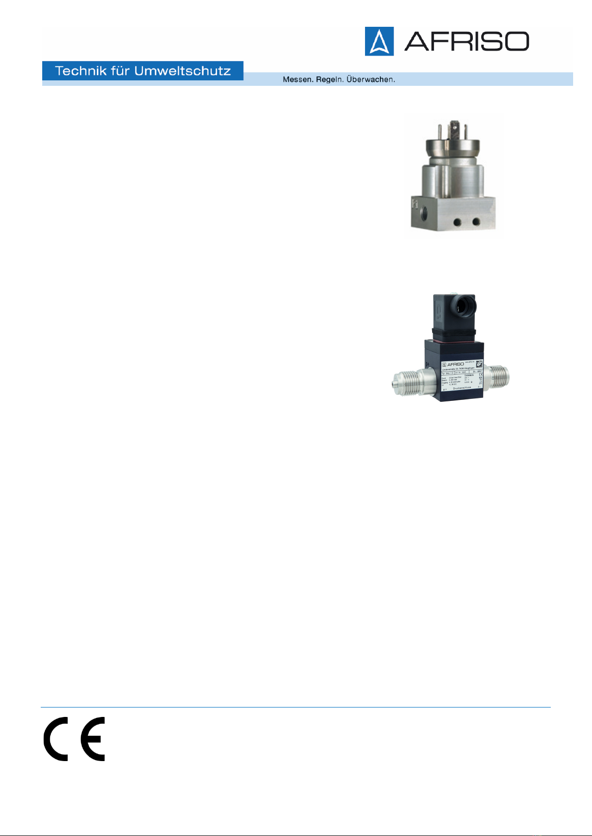
•The differential pressure transmitters DMU 10 D and DMU 11 D are intended for
industrial applications. The compact design allows a simple integration even in
constructions and machines with restricted space conditions.
•Base elements of DMU 10 D are 2 piezoresistive stainless steel sensors. DMU 11 D is
based on a piezoresistive silicon pressure sensor.
•For both sided pressure admission, the difference of the pressure between positive and
negative side is established and converted into a proportional electrical signal.
•DMU 10 D comes into operation e. g. in engineering and plant construction for filter
controlling and flow measurement as well as in hydraulic applications. As media, fluids
and gases are suitable, which are compatible with the sealing material as well as with
stainless steel 1.4571 and 1.4435.
•DMU 11 D is intended for the application in the filter controlling and air conditioning
technology. As media, non-aggressive gases and pressured air are suitable.
•The application of both differential pressure transmitters DMU 10 D and DMU 11 D is
summarized in this operating instruction, but the devices differ in the technical data
which can be taken out of the current data sheet.
•Use the device according to the area of application specified above! Furthermore,
compatibility with the medium to be measured has to be assumed.
•No liability is assumed and warranty claims are excluded in case of improper applica-
tion, modification of or damage to the device.
1.2 Target group
This operating instructions are intended for qualified technical personnel.
1.3 Symbols used
:: Caution! : Note
1.4 Safety notes
Observe the following notes:
The device may only be installed, used and serviced by persons who are familiar
with this operating manual!
Observe the applicable laws regarding occupational safety, accident prevention and
national installation standards!
The device must only be used within the specifications! (Compare the technical data
in the current data sheet)
Install the device in the depressurized and mechanical tension condition!

DMU 10 / DMU 11
3
2. Product identification
The device can be identified by its type plate. It provides the most important data. By the or-
dering code, the product can be clearly identified.
Fig. 1: type plate DMU 11 D
3. Installation
3.1 Assembly information
•Keep in mind that this device is an electronic precision measuring device. Handle the de-vice
carefully and properly to avoid any damages!
•Do not throw the device!
•Remove the packaging and, if necessary, the protective cap of the device only shortly before
installation in order to prevent damage to the diaphragm!
•Keep the protective cap!
•After disassembling, reattach this protective cap over the diaphragm.
•Handle an unprotected membrane with extreme care; This can be easily damaged.
•Do not use any force when installing the devices!
•Make sure that no mechanical stresses occur at the pressure port with low pressure ranges
during installation, as this may cause a shifting of the characteristic curve..
•For the connection of the pressure lines, a sealing has to be installed by the operator.
•For the pipe assembly, an installation as zero-potential as possible must be observed.
•Consider for the installation of a DMU 10 D, that the pressure ports must not be turned
against the housing!
3.2 General installation steps
1. Remove the pressure measuring device from the package carefully.
2. Connect the reference pressures according to the following installation steps
and to your mechanical connections. Therefore, you will have to observe that:
- The higher pressure must be connected with the input "+" (DMU 10 D) or
"P1" (DMU 11 D)
- The lower pressure must be connected with the input "-" (DMU 10 D) or
"P2" (DMU 11 D)
Typ
designation
Serial
number
Signal
Suppy
Diff. Pressure range
Ordering
code
Connector
pinout

4
3. Fix the device according to their demands on the holder or holding angle intended
for it.
- For mounting the device, four mounting threads (M4) are provided.
- For DMU 11 D in addition, the possibility is given to mount the device by using the
two holes (∅4,5 mm).
Fig. 2 Mounting possibilities
3.3 Installation steps for DMU 10 D with G 1/8" internal thread
•Check to ensure that the O-rings fit properly into the grooves.
(O-rings are not included in the scope of delivery.)
•Make sure that the sealing surfaces of the fittings are perfectly smooth and clean.
•Screw the fittings into the threads by hand.
•To tighten the fittings properly, hold the DMD 331 on the spanner flat SW 22 of the
respective pressure port with one hand and then tighten it (max. 20 Nm).
3.4 Installation steps for DMU 11 D with G 1/8" internal thread
•Seal the pressure ports of the differential pressure transmitter in a way that is suitable for
your application. (Seals are not included in the scope of delivery.)
•Screw the fittings into the threads as far as possible.
•Tighten the fittings properly (max. 10 Nm).
3.5 Installation steps for DMU 11 D with tube nozzle ∅6,6 x 11
•Slip your flexible tubes (∅6 mm) onto the tube nozzles as far as possible.
3.6 Electrical connection
Establish the electrical connection of the device complying with your plug according to the
pin configuration shown on the type plate and in the following table.
For devices with cable gland as well as cable socket, you have to make sure that the ex-
ternal diameter of the used cable is within the allowed clamping range. Moreover you
have to ensure that it lies in the cable gland firmly and cleftlessly.
mounting threads holes

DMU 10 / DMU 11
5
Please note for devices with ISO 4400 plug and cable socket, that the socket has to be
mounted properly to ensure the ingress protection, mentioned in the data sheet. Please
check if the delivered seal is placed between plug and cable socket. Fasten the cable
socket on the device by using the screw, after connecting the cable.
Pin configuration:
DMU 10 D
DMU 11 D
Electrical connection
ISO 4400
IP 65
Brad
Harrison
Mini Change
IP 67
ISO 4400
IP 65
M12x1
(4-pin)
IP 67
cable gland
IP 67
2-wire-system
Supply +
Supply –
1
2
A
B
1
2
1
2
wh (white)
bn (brown)
Ground ground
contact C ground
contact 4
gnye
(green-yel-
low)
(shield)
3-wire-system
Supply +
Supply –
Signal +
1
2
3
-
-
-
1
2
3
1
2
3
wh (white)
bn (brown)
gn (green)
Ground ground
contact - ground
contact 4
gnye
(green-yel-
low) (shield)
Wiring diagrams
2-wire-system (current) 3-wire-system (current / voltage)
For the electrical connection, use a shielded cable.
supply +
signal +
VS
A/V
p
I/U
supply –
P supply +
supply –
VS
I

6
4. Commissioning
Please note that for starting up, the device has to be stressed by pressure simultaneously at
both pressure ports. Otherwise the sensor could be damaged. For one-sided pressure
admission, the permissible static pressure (one-sided) must be attended. Please take this out
of the current data sheet.
5. Troubleshooting
Problem
Problem reason
Error detection / corrective
no output signal
- connected incorrectly
- line break
- defective amperemeter
(signal input)
- inspect the connection
- inspect all line connections nec-
essary to supply the device (in-
cluding the connector plugs)
- Inspect the amperemeter (fine-
wire fuse) or the analog input of
your PLC
analog output signal
too low
- load resistance too high
- supply voltage too low
- defective energy supply
- verify the value of the load
resistance
- verify the output voltage of the
power supply
- inspect the power supply and the
applied supply voltage at the
device
shifting of the output
signal
- diaphragm is contaminated or
damaged
- please return the device to us for
repair
wrong or no output
signal
- electrical connection is dam-
aged
- reverse polarity of the pres-
sure ranges
-
check the connections
- check if the higher pressure is
connected with the input "+" (DMU
10 D) or "P1" (DMU 11 D)
If you detect an error, please try to eliminate it by this table or send the device to our service
address for repair.
Repairs on the device may only be performed by the manufacturer!

DMU 10 / DMU 11
7
6. Decommissioning
When dismantling the device, it must always be done in the depressurized and
currentless condition!
7. Maintenance
In principle, the device requires no maintenance.
If necessary, clean the housing of the device using a moist cloth and a non-aggressive cleaning
solution.
8. Recalibration
The offset value or range value may shift during the life of the device. In this case, a devia-
ting signal value in relation to the set lower or upper measuring range value is output. If one
of these two phenomena occurs after extended use, a recalibration in the factory is recom-
mended. Please note the chapter “Service/Repair” with regard to this.
9. Returning the device
Get in touch with us before returning your product (service@afriso.de).
A declaration of decontamination must be enclosed with the device for every return, regar-
dless of whether it is for recalibration, decalcification, conversion or repair. Corresponding
templates can be found on our homepage.
Devices without a declaration of decontamination will only be examined after receipt of a
corresponding declaration in case of doubt regarding the medium used!
10. Decommissioning, diposall
Dispose of the product in compliance with all applicable directives, standards and safety
regulations.
1. Disconnect the product from mains.
2.
Dismount the product (see chapter "Mounting", reverse sequence of
steps).
3. Dispose of the product.
11. Warranty
See our terms and conditions at www.afriso.com or your purchase contract for information on
warranty.

8
12. EU Declaration of Conformity
This manual suits for next models
15
Table of contents
Other AFRISO Transmitter manuals
Popular Transmitter manuals by other brands

Endress+Hauser
Endress+Hauser Liquiline CM42 Brief operating instructions

Vega
Vega VEGABAR 86 Quick setup guide

AirLink Communications
AirLink Communications Raven X HSDPA user guide

Emergency Caller Products
Emergency Caller Products XP-5-300 user manual

Conrad Electronic
Conrad Electronic FS20 FMS operating instructions

Emerson
Emerson Fisher FIELDVUE 4400 instruction manual