PR 6337 User manual

SIGNALS THE BEST
6337
2-wire HART®
Transmitter
No. 6337V100-UK
From ser. no. 110944345

1236
PR electronics A/S tilbyder et bredt program af analoge og digitale
signalbehandlingsmoduler til industriel automation. Programmet
består af Isolatorer, Displays, Ex-barrierer, Temperaturtransmittere,
Universaltransmittere m. Vi har modulerne, du kan stole på i selv
barske miljøer med elektrisk støj, vibrationer og temperaturud-
sving, og alle produkter opfylder de strengeste internationale stan-
darder. Vores motto »Signals the Best« er indbegrebet af denne
loso – og din garanti for kvalitet.
PR electronics A/S offers a wide range of analogue and digital
signal conditioning devices for industrial automation. The product
range includes Isolators, Displays, Ex Interfaces, Temperature
Transmitters, and Universal Devices. You can trust our products
in the most extreme environments with electrical noise, vibrations
and temperature uctuations, and all products comply with the
most exacting international standards. »Signals the Best« is the
epitome of our philosophy – and your guarantee for quality.
PR electronics A/S offre une large gamme de produits pour le
traitement des signaux analogiques et numériques dans tous
les domaines industriels. La gamme de produits s’étend des
transmetteurs de température aux afcheurs, des isolateurs aux
interfaces SI, jusqu’aux modules universels. Vous pouvez compter
sur nos produits même dans les conditions d’utilisation sévères,
p.ex. bruit électrique, vibrations et uctuations de température.
Tous nos produits sont conformes aux normes internationales les
plus strictes. Notre devise »SIGNALS the BEST« c’est notre ligne
de conduite - et pour vous l’assurance de la meilleure qualité.
PR electronics A/S verfügt über ein breites Produktprogramm
an analogen und digitalen Signalverarbeitungsmodule für die in-
dustrielle Automatisierung. Dieses Programm umfasst Displays,
Temperaturtransmitter, Ex- und galvanische Signaltrenner, und
Universalgeräte. Sie können unsere Geräte auch unter extremen
Einsatzbedingungen wie elektrisches Rauschen, Erschütterungen
und Temperaturschwingungen vertrauen, und alle Produkte von
PR electronics werden in Übereinstimmung mit den strengsten
internationalen Normen produziert. »Signals the Best« ist Ihre
Garantie für Qualität!
DK
UK
FR
DE

6337V100-IN 1
2-WIRE HART®TRANSMITTER
PRETRANS 6337
CONTENTS
EC declaration of conformity ............................................. 2
Application ......................................................................... 3
Technical characteristics.................................................... 3
Mounting / installation / programming............................... 4
Applications........................................................................ 5
Accessories........................................................................ 6
Ordering codes for 6337 .................................................... 6
Technical data .................................................................... 6
Switching HART®protocol revision.................................... 9
Connections ....................................................................... 11
Block diagram .................................................................... 13
Programming...................................................................... 14
Connection of transmitters in multidrop mode.................. 16
Appendix ............................................................................ 17
ATEX Installation Drawing - 6337A.................................. 18
IECEx Installation Drawing - 6337A ................................ 20
ATEX Installation Drawing - 6337D ................................. 22
IECEx Installation Drawing - 6337D................................ 24
FM Installation Drawing - 6337D..................................... 26
CSA Installation Drawing - 6337D................................... 27

2 6337V100-IN
EC DECLARATION OF CONFORMITY
As manufacturer
PR electronics A/S
Lerbakken 10
DK-8410 Rønde
hereby declares that the following product:
Type: 6337
Name: 2-wire HART®transmitter
is in conformity with the following directives and standards:
The EMC Directive 2004/108/EC and later amendments
EN 61326-1 : 2006
For specification of the acceptable EMC performance level, refer to the
electrical specifications for the device.
The ATEX Directive 94/9/EC and later amendments
EN 60079-0 : 2009, EN 60079-11 : 2007,
EN 60079-15 : 2010, EN 60079-26 : 2007
and EN 61241-11 : 2006
ATEX certificate: KEMA 10ATEX0006 X (6337A)
ATEX certificate: KEMA 09ATEX0148 (6337D)
Notified body
DEKRA Certification B.V. (0344)
Utrechtseweg 310, 6812 AR Arnhem
P.O. Box 5185, 6802 ED Arnhem
The Netherlands
Rønde, 23 March 2012 Kim Rasmussen
Manufacturer’s signature

6337V100-IN 3
PRETRANS 6337
2-WIRE HART®TRANSMITTER
• RTD, TC, Ohm, or mV input
• 2 analogue inputs and 5 device variables with status
available
• HART® protocol revision selectable from HART® 5 or
HART® 7
• Hardware assessed for use in SIL applications
• Mounting on a DIN rail in safe area or hazardous gas
and dust area
Application
• LinearisedtemperaturemeasurementwithTCandRTDsensorse.gPt100
and Ni100.
• HART®communication and 4...20 mA analogue PV output for individual,
difference or average temperature measurement of up to two RTD or
TC input sensors.
• Conversionoflinearresistancetoastandardanaloguecurrentsignal,e.g
from valves or Ohmic level sensors.
• AmplificationofbipolarmVsignalstostandard4...20mAcurrentsignals.
• Upto63transmitters(HART®7) can be connected in a multidrop
communication setup.

4 6337V100-IN
Technical characteristics
• HART®protocol revision can be changed by user configuration to either
HART®5 or HART®7 protocol.
• TheHART®7 protocol offers:
∙ Long Tag numbers of up to 32 characters.
∙ Enhanced Burst Mode and Event notification with time stamping.
∙ Device variable and status mapping to any dynamic variable PV, SV, TV or QV.
∙ Process signal trend measurement with logs and summary data.
∙ Automatic event notification with time stamps.
∙ Command aggregation for higher communication efficiency.
• 6337isdesignedaccordingtostrictsafetyrequirementsandisthereforesuit
able for applications in SIL installations.
• Continuouscheckofvitalstoreddata.
• MeetingtheNAMURNE21recommendations,the6337HARTtransmit-
ter ensures top measurement performance in harsh EMC environments.
Additionally, the 6337 meets NAMUR NE 43 and NE 89 recommendations.
Mounting / installation / programming
• DINrailmountingwithupto84channelspermetre.
• ConfigurationviastandardHART®communication interfaces or by PR 5909
Loop Link.
• NB:AsExbarrierfor6337Dwerecommend5106Band9106B.

6337V100-IN 5
APPLICATIONS
V+
mA
V+
mA
V+
mA
V+
mA
V+
mA
12
2
12
1
RTD to 4...20 mA
TC to 4...20 mA
Resistance
to 4...20 mA
Difference or average
RTD, TC or mV
2-wire installation
in control room
2-wire installation
in control room
2-wire installation
in control room
2-wire installation
in control room
mV to 4...20 mA 2-wire installation
in control room

6 6337V100-IN
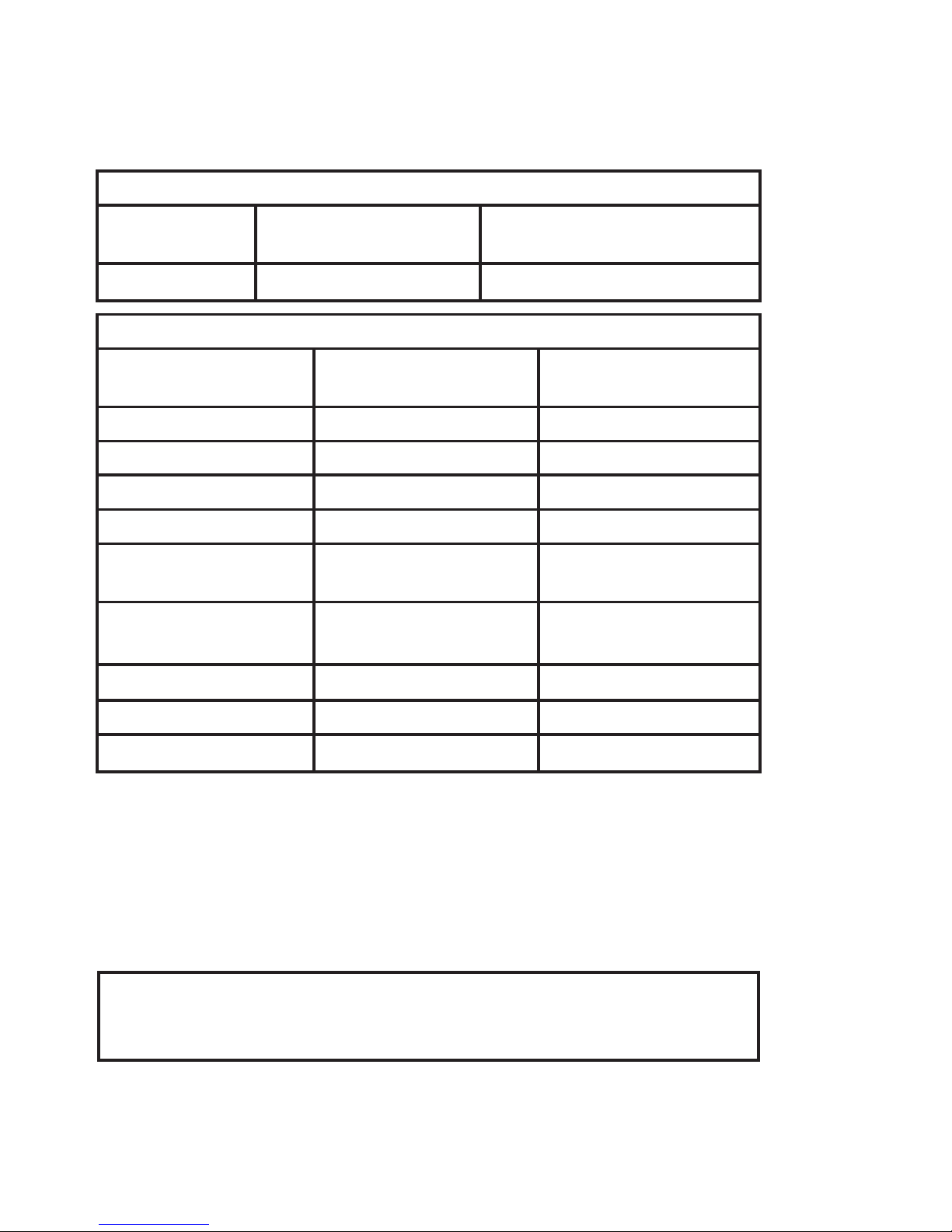
Technical data
Environmental conditions:
Specifications range.................................... -40°C to +60°C
Storage temperature ................................... -40°C to +85°C
Calibration temperature............................... 20...28°C
Relative humidity......................................... <95%RH(noncond.)
Protection degree........................................ IP20
Mechanical specifications:
Dimensions(HxWxD)................................... 109 x 23.5 x 104 mm
Weightapprox.,1/2ch.version .............. 150 / 200 g
DIN rail type................................................. DIN EN 60715 - 35mm
Wiresize ...................................................... 0.13...2.08 mm2/AWG
26...14 stranded wire
Screw terminal torque................................. 0.5 Nm
Common electrical specifications:
Supply voltage, DC:
Standard............................................... 8.0...35 V
ATEX, CSA, FM & IECEx...................... 8.0...30 V
Voltage drop ................................................ 8.0 V
Isolation voltage, test / operation................ 1.5 kVAC / 50 VAC
Isolation voltage, channel 1 / channel 2:
Standard............................................... 3.75 kVAC
ATEX, CSA, FM & IECEx...................... 1.5 kVAC
Ordering codes for 6337
5909 = Loop Link USB interface and PReset Software
5910 / 5910Ex = CJC connector for channel 1
5913 / 5913Ex = CJC connector for channel 2
Accessories
Type Version Galvanic
isolation Channels
6337 Standard : A
ATEX, CSA, FM & IECEx : D
1500 VAC : 2 Single : A
Double : B
6337V100-IN 7
Signal / noise ratio ...................................... > 60 dB
Communications interface .......................... Loop Link & HART®
Responsetime(programmable).. ................ 1...60 s
Accuracy, the greater of general and basic values:
TC
B1accuracy specification range.......... > 400°C
TC
B2accuracy specification range.......... > 160°C < 400°C
TC B3accuracy specification range ......... > 85°C < 160°C
TC B4accuracy specification range ......... < 85°C
TC cold junction compensation .................. < ±1.0°C
Max. offset on input signal.......................... 50% of selec. max. value
Basic values
Input type Basic
accuracy Temperature
coefficient
Pt50 - Pt1000 ≤ ±0.1°C ≤ ±0.005°C/°C
Ni50 - Ni1000 ≤ ±0.2°C ≤ ±0.005°C/°C
Lin. R ≤ ±0.1 Ω ≤±5mW/°C
Volt ≤ ±10 µV ≤ ±0.5 µV / °C
TC type:
E, J, K, L, N, T, U
≤ ±0.5°C
≤ ±0.025°C / °C
TC type:
B1,Lr,R,S,W3,W5
≤ ±1°C
≤ ±0.1°C / °C
TC type:B2≤ ±3°C ≤ ±0.3°C / °C
TC type:B3≤ ±8°C ≤ ±0.8°C / °C
TC type:B4not specified not specified
General values
Input type Absolute
accuracy Temperature
coefficient
All ≤ ±0.05% of span ≤ ±0.005% of span / °C
EMC immunity influence ..................................... < ±0.1% of span
Extended EMC immunity:
NAMUR NE 21, A criterion, burst ....................... < ±1% of span

8 6337V100-IN
Input specifications:
RTD input types:
Pt50, Pt100, Pt200, Pt500, Pt1000, Ni50, Ni100, Ni120, Ni1000
Cableresistanceperwire(max.)................. 50 Ω
Sensor current............................................. Nom. 0.2 mA
TC input types:
Coldjunctioncompensation(CJC):
Constant, internal or external via a Pt100 or Ni100 sensor
mV input:
Voltage input range ..................................... -800...+800 mV
Min. span..................................................... 2.5 mV
Input resistance........................................... 10 MΩ
RTD
type Min.
value Max.
values Min.
span Standard
Pt100
Ni100
Lin. R
-200°C
-60°C
0 Ω
+850°C
+250°C
7000 Ω
10°C
10°C
25 Ω
IEC 60751
DIN 43760
-----
Type Min.
temperature Max.
temperature Min.
span
Standard
B
E
J
K
L
Lr
N
R
S
T
U
W3
W5
0°C
-100°C
-100°C
-180°C
-200°C
-200°C
-180°C
-50°C
-50°C
-200°C
-200°C
0°C
0°C
+1820°C
+1000°C
+1200°C
+1372°C
+900°C
+800°C
+1300°C
+1760°C
+1760°C
+400°C
+600°C
+2300°C
+2300°C
100°C
50°C
50°C
50°C
50°C
50°C
50°C
100°C
100°C
50°C
50°C
100°C
100°C
IEC584
IEC584
IEC584
IEC584
DIN 43710
GOST 3044-84
IEC584
IEC584
IEC584
IEC584
DIN 43710
ASTM E988-90
ASTM E988-90

6337V100-IN 9
Output specifications and HART®:
Signal range ................................................ 4...20 mA
Min. signal range......................................... 16 mA
Updating time.............................................. 440 ms
Load resistance........................................... ≤(Vsupply - 8) / 0.023 [Ω]
Sensor error detection, programmable....... 3.5...23mA
NAMUR NE43 Upscale ............................... 23 mA
NAMUR NE43 Downscale........................... 3.5 mA
HART®protocol revisions ........................... HART® 5 and HART® 7
Switching HART®protocol revision
It is possible to change the HART®protocol revision by using the PReset
software and a PR 5909 Loop Link interface or a HART®compatible modem.
Other HART®configuration tools like a handheld terminal can also be used.
Switching protocol from HART®7 to HART®5:
Procedure when using the PR PReset Software:
Enter the 6337 PReset tab ”HART” and open the folder ”Methods”.
Click ”Device Password / Write Protection / Protocol...” and select ”Change
protocol to HART 5” in the pop-up window - acknowledge by pressing OK.
Please note that this action will change the 6337 into a 6335 device.
Switching from HART®5 to HART®7:
Please note that this is only possible if the transmitter is label marked as ”6337”!
Enter the 6335 PReset tab ”OPTIONS” and click ”Protect”.
WriteprotectionmustbesetONandselectChange Password.
Type in the New Password ”HARTREV7” and Re-enter ”HARTREV7”. Press OK.
Switch Write protection OFF and write enable the device by typing in the
Password ”-CHANGE-” in the top menu - acknowledge by pressing OK.
Theaboveactionwillresetthepasswordtothedefaultactivepassword(”********”)
and restart the device in the updated HART 7 mode with write protection disabled.
Please note that the configuration changed flags and configuration changed
counter are not updated by this command.

10 6337V100-IN
Approvals:
EMC 2004/108/EC ...................................... EN 61326-1
GOST R
Ex / I.S.:
6337A:
ATEX 94/9/EC....................................... KEMA 10ATEX0006 X
IECEx ................................................... KEM 10.0084 X
6337D:
ATEX 94/9/EC....................................... KEMA 09ATEX0148 X
IECEx ................................................... KEM 10.0083 X
FM certificate ....................................... 2D5A7
CSA certificate ..................................... 1125003
GOST Ex
Functional Safety:
Hardware assessed for use in SIL applications
FMEDA report - www.prelectronics.com

6337V100-IN 11
51 52 54
53
51 52 54
53 51 52 54
53
41 42 44
43
42 44
43
41 41 42 44
43
41 42 44
43
+
-
41 42 44
43 41 42 44
43 41 42 44
43
51 52 54
53
+
-
51 52 54
53 51 52 54
53 51 52 54
53
51 54
CJC
52
41 42 44
CJC
+
-
+
-
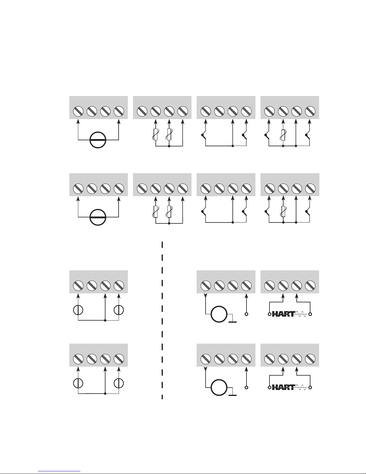
Channel 1Channel 2 Channel 2
Inputs:
Channel 1
RTD, 2-wire RTD, 3-wire RTD, 4-wire TC, internal CJC
TC, internal CJC
RTD, 2-wire RTD, 3-wire RTD, 4-wire
Resistance, 2-wire Resistance, 3-wire Resistance, 4-wire
TC, external CJC
Resistance, 2-wire Resistance, 3-wire Resistance, 4-wire
TC, external CJC
CONNECTIONS
12 6337V100-IN
CONNECTIONS
41 42 44
43 11 12 14
13 11 12 14
13
51 52 54
53 21 22 24
23 21 22 24
23
+
-
1
+
-
2
+
-
1
+
-
2
+
mA
+
mA
51 52 54
CJC
+
-
1
+
-
2
51 52 54
53
+
-
1
+
-
2
41 42 44
43
+
-
51 52 54
53
+
-
41 42 44
43
1
2
51 52 54
53
1
2
41 42 44
+
-
1
+
-
2
41 42 44
43
+
-
1
+
-
2
CJC
Outputs:
Channel 2
Inputs:
Channel 1
mV
mV
Channel 1Channel 2
2-wire installation
2-wire installation
TC, dierence
or average,
with internal CJC
TC, dierence
or average,
with internal CJC
TC, dierence
or average,
with external CJC
TC, dierence
or average,
with external CJC
mV, dierence
or average
mV, dierence
or average
RTD, dierence
or average
RTD, dierence
or average
HART®comm.
HART®comm.
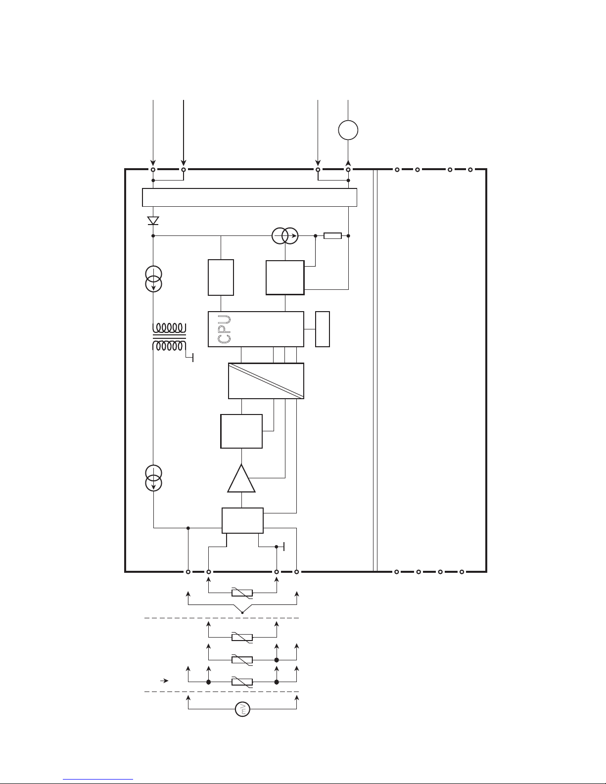
6337V100-IN 13
0...16
mA
4 3 2
*
44
14
13
11
12
43
42
41
53
54
51
52
23
24
22
21
+
-
mV
mA
MUX
4 mA
PGA
D / A
A / D
CH 1
CH 2
+
-
CPU
EEPROM
6337
6337
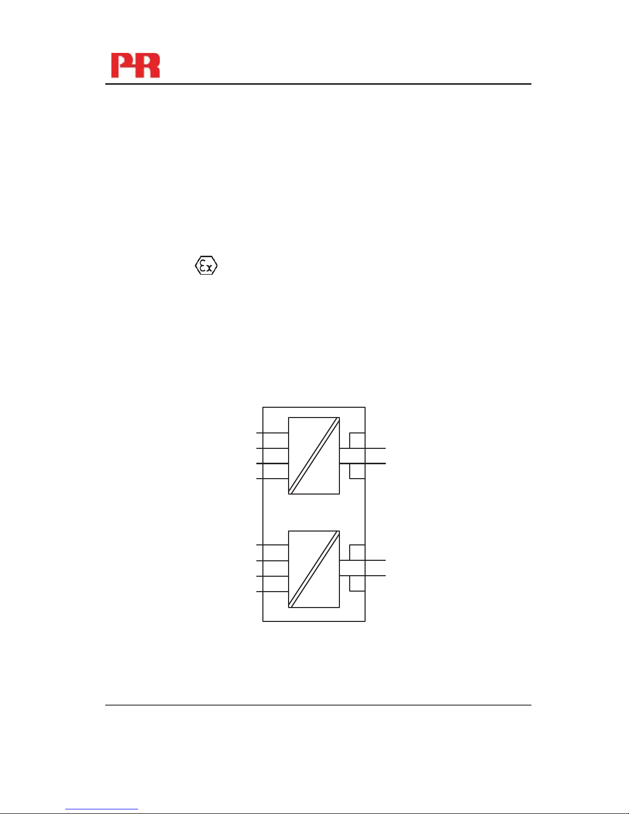
Supply -
4...20 mA
TC
mV RTD, lin. R
- wire
Ex circuit, only 6337D
*
Internal CJC connectors must be ordered separately.
Supply +
HART®comm.
HART®comm.
Comm.
BLOCK DIAGRAM
14 6337V100-IN
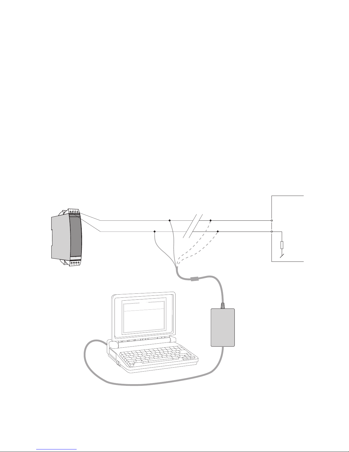
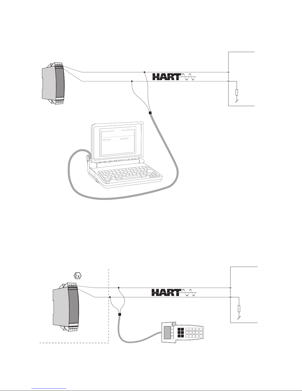
PROGRAMMING
PRetrans 6337 can be configured in the following 3 ways:
1.WithPRelectronicsA/S’communicationsinterfaceLoopLinkandPResetPC
configuration software.
2.WithaHART®modem and PReset PC configuration software.
3.WithaHART®communicator with PR electronics A/S’ DDL driver.
1: Loop Link
For programming please refer to the drawing below and the help functions in
PReset.
Whencommunicatingwithnoninstalleddevices,connectors11,12,13,14
(channel1)and21,22,23,24(channel2)canbedismantledinthesafearea
to connect the terminals of the communications interface to the pins.
Loop Link is not approved for communication with devices installed in
hazardous(Ex)area.
6337
*
*
44
43
42
41
51
12
111
2
1
3
1
4
14 (24)
11 (21)
FileProductInputOutputCommunication Language
Option08:30:00
PRetop5331
Date:2004-8-10
043201594
PRelectronics
AnaloginputAnal ogoutput
Serial no:
Inputtype:Outputtype:4 -20mA
Upscale
Sensorerror:
Pt100DIN/IEC
0.00 -50.00C
3-wire
1.00sec
------
Inputrange:
Connection:
Coldjunctioncomp:
Response time:
Tag no:
Loop
Link
5909 - USB
5905 - RS232
Disconnect
+Vsupply
* Connected only for
on-line programming
Black
Red Yellow
Green
Input
Receiving
equipment
Connector
6337V100-IN 15
13 (23)
12 (22)
F
i
l
e
P
r
o
d
u
c
t
I
n
p
u
t
O
u
t
p
u
t
C
o
m
m
u
n
i
c
a
t
i
o
n
L
a
n
g
u
a
g
e
O
p
t
i
o
n
0
8
:
3
0
:
0
0
P
R
e
t
o
p
5
3
3
1
D
a
t
e
: 1
9
9
4
-
8
-
1
0
9
4
3
2
0
1
5
9
4
P
R
e
l
e
c
t
r
o
n
i
c
s
A
n
a
l
o
g
i
n
p
u
t A
n
a
l
o
g
o
u
t
p
u
t
S
e
r
i
a
l
n
o
:
I
n
p
u
t
t
y
p
e
: O
u
t
p
u
t
t
y
p
e
: 4
-
2
0
m
A
U
p
s
c
a
l
e
S
e
n
s
o
r
e
r
r
o
r
:
P
t
1
0
0
D
I
N
/
I
E
C
0
.
0
0
-
5
0
.
0
0
C
3
-
w
i
r
e
1
.
0
0
s
e
c
-
-
-
-
-
-
I
n
p
u
t
r
a
n
g
e
:
C
o
n
n
e
c
t
i
o
n
:
C
o
l
d
j
u
n
c
t
i
o
n
c
o
m
p
:
R
e
s
p
o
n
s
e
t
i
m
e
:
T
a
g
n
o
:
4 4
4
3
4
2
41
51
12
1
1 1
2
1
3
1
4
6337
+Vsupply
Input
Receiving
equipment
Rload > 250 Ω, < 1100 Ω
HART®modem
4
4
4
3
4
2
41
51
12
1
1 1
2
1
3
1
4
13 (23)
12 (22)
6337
Safe area
+Vsupply
Input
Receiving
equipment
area
Rload > 250 Ω, < 1100 Ω
12 (22)
2: HART®modem
For programming please refer to the drawing below and the help functions in
PReset.
3: HART®communicator
For programming please refer to the drawing below. To get access to product-
specific commands, the HART®communicator must be loaded with the
PR electronics A/S DDL driver. This can be ordered either at the HART®
Communication Foundation or PR electronics A/S.

16 6337V100-IN
CONNECTION OF TRANSMITTERS
IN MULTIDROP MODE
• TheHART®communicator or a PC modem can be connected accross AB or
BC.
• Theoutputsofmax.63transmitterscanbeconectedinparallelforadigital
HART®communication on 2-wires.
• Beforeitisconnected,eachtransmittermustbeconfiguredwithaunique
number from 1 to 63. If 2 transmitters are configured with the same number,
both will be excluded. The transmitters must be programmed for multidrop
mode(withafixedoutputsignalof4mA).Maximumcurrentintheloopis
therefore 252 mA.
• ThecommunicationiseitherbymeansofaHART®communicator or a
HART®modem.
• ThePResetPCconfigurationsoftwarecanconfiguretheindividualtransmitter
for multidrop mode and provide it with a unique polling address.
R
A
B
C
PRetrans
6337
PRetrans
6337
PRetrans
6337
+
-
+
-
Power
supply
Rload >250 ohm,<1100 ohm Max. 63 channels

6337V100-IN 17
APPENDIX
ATEX INSTALLATION DRAWING - 6337A
IECEX INSTALLATION DRAWING - 6337A
ATEX INSTALLATION DRAWING - 6337D
IECEX INSTALLATION DRAWING - 6337D
FM INSTALLATION DRAWING NO. 6335QF01
CSA INSTALLATION DRAWING NO. 6335QC02
18 6337V100-IN
6335QA02
LERBAKKEN 10, 8410 RØNDE DENMARK. WWW.PRELECTRONICS.COM
Revision date:
2011-02-01
Version Revision
V3R0
Page:
1/2
ATEX Installation drawing
For safe installation of 6335A, 6336A or 6337A the following must be observed. The module shall
only be Installed by qualified personnel who are familiar with the national and international laws,
directives and standards that apply to this area.
Year of manufacture can be taken from the first two digits in the serial number.
ATEX Certificate KEMA 10ATEX 0006X
Marking
Standards EN 60079-0 : 2009, EN 60079-11:2007,
EN 60079-15: 2010, EN 61241-11:2006
II 3 G Ex nA [ic] IIC T6 Gc
II 3 G Ex ic IIC T6 Gc
II 3 D Ex ic IIIC Dc
Hazardous Area Zone 2 or Zone 22
T6: -40ºC to 60 ºC
Terminal:
41,42,43,44 /
51,52,53,54
Ex nA [ic]
Uo: 9.6 VDC
Io: 28 mA
Po: 67 mW
Lo: 35 mH
Co: 3.5μF
Terminal:
11,12,13,14
21,22,23,24
Ex nA
U ≤35 VDC
I = 4 - 20 mA
Ex ic
Ui : 35 VDC
Li : 10 μH
Ci : 2.0 nF
13
12
44
43
42
41
+
-
23
22
54
53
52
51
+
-
6335A
6336A
6337A
CH2
CH1
21
24
14
11
Table of contents
Other PR Transmitter manuals


Popular Transmitter manuals by other brands


Evikon
Evikon E2615-CO user manual

Magenta
Magenta MultiView II DVI-TX quick start guide

Emerson
Emerson Rosemount Oxymitter 4000 Reference manual

Extron electronics
Extron electronics DTP2 T 201 D Series Setup guide

Emerson
Emerson Rosemount 3051S Series quick start guide

Burkert
Burkert 8312 Series operating manual


