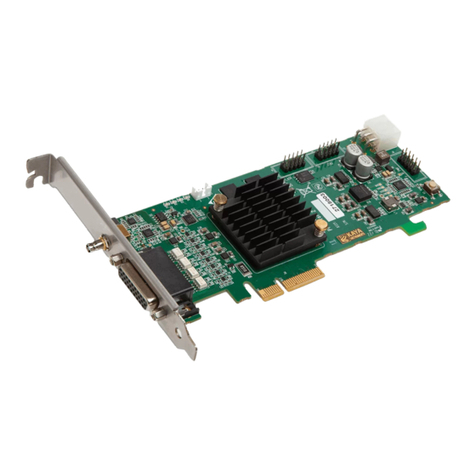
Kaya Instruments GPIO Product guide

GPIO expansion bracket for the Komodo and
Predator frame grabbers
Data Bookv1.2
Sky Blue Microsystems GmbH
Geisenhausenerstr. 18
81379 Munich, Germany
www.skyblue.de
In Great Britain:
Zerif Technologies Ltd.
Winnington House, 2 Woodberry Grove
Finchley, London N12 0DR
www.zerif.co.uk
International Distributors

GPIO expansion bracket for the Komodo and Predator frame grabbers Data
Book
1
1Figures and Tables..........................................................................................................2
2Introduction....................................................................................................................3
2.1 Safety Precautions................................................................................................3
2.2 Disclaimer............................................................................................................4
3Key Features ..................................................................................................................5
3.1 Overview ................................................................................................................. 5
3.2 Features.................................................................................................................... 5
3.3 Related documents and accessories......................................................................... 5
4System Description.........................................................................................................6
4.1 Komodo frame grabber general purpose I\O........................................................... 6
4.2 Predator frame grabber general purpose I\O (rev 3 and higher only) ..................... 8
5Connectivity...................................................................................................................9
5.1 KY_GPIO connection ............................................................................................. 9
5.2 Installation instructions ........................................................................................... 10
Contents

GPIO expansion bracket for the Komodo and Predator frame grabbers Data
Book
2
Figures
FIGURE 1:KY_GPIO CONNECTION......................................................................................................9
Tables
TABLE 1:GPIO PIN ASSIGNMENTS,SIGNAL NAME AND FUNCTIONS FOR KOMODO J1...........................6
TABLE 2:GPIO PIN ASSIGNMENTS,SIGNAL NAME AND FUNCTIONS FOR KOMODO J2...........................7
TABLE 3:GPIO PIN ASSIGNMENTS,SIGNAL NAME AND FUNCTIONS FOR PREDATOR J18......................8
TABLE 4:KY_GPIO CONNECTION.......................................................................................................9
Revision History
Version
Date
Notes
1.0
13.3.16
Initial release
1.1
6.1.17
Updated Predator (rev 3) frame grabber IO
1.2
25. 9.17
Change GPIO pin assignments Table 1 and Table 2
1Figures and Tables

GPIO expansion bracket for the Komodo and Predator frame grabbers Data
Book
3
2.1 Safety Precautions
With your GPIO expansion (KY-GPIO)connector in hand, please take a minute to read carefully
the precautions listed below in order to prevent unnecessary injuries to you or other personnel or
cause damage to property.
Before using the product, read these safety precautions carefully to assure correct use.
These precautions contain serious safety instructions that must be observed.
After reading through this manual, be sure to act upon it to prevent misuse of product.
Caution
In the event of a failure, disconnect the power supply.
If the product is used as is, a fire or electric shock may occur. Disconnect the power supply
immediately and contact our sales personnel for repair.
If an unpleasant smell or smoking occurs, disconnect the power supply.
If the product is used as is, a fire or electric shock may occur. Disconnect the power supply
immediately. After verifying that no smoking is observed, contact our sales personnel for repair.
Do not disassemble, repair or modify the product.
Otherwise, a fire or electric shock may occur due to a short circuit or heat generation. For
inspection, modification or repair, contact our sales personnel.
Do not touch a cooling fan.
As a cooling fan rotates in high speed, do not put your hand close to it. Otherwise, it may cause
injury to persons. Never touch a rotating cooling fan.
Do not place the product on unstable locations.
Otherwise, it may drop or fall, resulting in injury to persons or failure.
If the product is dropped or damaged, do not use it as is.
Otherwise, a fire or electric shock may occur.
Do not touch the product with a metallic object.
Otherwise, a fire or electric shock may occur.
Do not place the product in dusty or humid locations or where water may splash.
Otherwise, a fire or electric shock may occur.
Do not get the product wet or touch it with a wet hand.
Otherwise, the product may break down or it may cause a fire, smoking or electric shock.
Do not touch a connector on the product (gold-plated portion).
Otherwise, the surface of a connector may be contaminated with sweat or skin oil, resulting in
contact failure of a connector or it may cause a malfunction, fire or electric shock due to static
electricity.
2Introduction

GPIO expansion bracket for the Komodo and Predator frame grabbers Data
Book
4
Do not use or place the product in the following locations.
● Humid and dusty locations
● Airless locations such as closet or bookshelf
● Locations which receive oily smoke or steam
● Locations close to heating equipment
● Closed inside of a car where the temperature becomes high
● Static electricity replete locations
● Locations close to water or chemicals
Otherwise, a fire, electric shock, accident or deformation may occur due to a short circuit or heat
generation.
Do not place heavy things on the product.
Otherwise, the product may be damaged.
2.2 Disclaimer
This product should be used only with KAYA's frame grabbers, for digital input/output (GPIO)
purposes. KAYA Instruments assumes no responsibility for any damages resulting from the use of
this product for purposes other than those stated.
Even if the product is used properly, KAYA Instruments assumes no responsibility for any damages
caused by the following:
- Earthquake, thunder, natural disaster or fire resulting from the use beyond our responsibility,
acts caused by a third party or other accidents, the customer’s willful or accidental misuse or use
under other abnormal conditions.
- Secondary impact arising from use of this product or its unusable state (business interruption or
others).
- Use of this product against the instructions given in this manual or malfunctions due to
connection to other devices.
KAYA Instruments assumes no responsibility or liability for:
- Erasure or corruption of data arising from use of this product.
- Any consequences or other abnormalities arising from use of this product, or damage of this
product not due to our responsibility or failure due to modification.
Repair of this product is carried out by replacing it on a chargeable basis, not repairing the faulty
devices. However, non-chargeable replacement is offered for initial failure if such notification is
received within two weeks after delivery of the product.
Introduction

GPIO expansion bracket for the Komodo and Predator frame grabbers Data
Book
5
3.1 Overview
The KY-GPIO is used together with the Komodo and Predator frame grabbers to gain easy access to
the GPIO connectors that are present on KAYA's frame grabbers. The KY-GPIO connected on one
side to the GPIO connector of the frame grabber and on the other side it's connected to a DB25
connector that is mounted on a standard full height bracket.
3.2 Features
Interfaces:
2 deferential LVDS inputs
2 deferential LVDS outputs
12 LVTTL inputs / outputs
4 inputs (optionally opto-isolated)
4 outputs (optionally opto-isolated)
4 inputs / outputs
4 TTL inputs / outputs
0°C to 50°C operating environment temperature
3.3 Related documents and accessories
Komodo CoaXPress Reference Guide
Komodo CoaXPress HW and Installation Guide
Komodo FXP HW and Installation Guide
Komodo FXCL HW and Installation Guide
Predator HW and Installation Guide
3Key Features

GPIO expansion bracket for the Komodo and Predator frame grabbers Data
Book
6
4.1 Komodo frame grabber general purpose I\O
The following table gives a brief functionality description of the various available GPIO signals on
the Komodo frame grabber, for more details please go to the relevant documentation.
Board
reference
(J1)
Signal Name
I/O Standard
Description
1
din[0]
LVDS
Pin 1 of this header is the positive signal and pin 2
in the negative signal of this LVDS. The differential
pair is converted to a single input on the FPGA
2
3
din[1]
LVDS
Pin 3 of this header is the positive signal and pin 4
in the negative signal of this LVDS. The differential
pair is converted to a single input on the FPGA
4
5
rout[0]
LVDS
Pin 5 of this header is the positive signal and pin 6
in the negative signal of this LVDS. The differential
pair is converted to a single output on the FPGA
6
7
rout[1]
LVDS
Pin 7 of this header is the positive signal and pin 8
in the negative signal of this LVDS. The differential
pair is converted to a single output on the FPGA
8
9
io_out[0]
3.3-V LVTTL
Optically isolated outputs
10
io_out[1]
3.3-V LVTTL
Optically isolated outputs
11
io_out[2]
3.3-V LVTTL
Optically isolated outputs
12
io_out[3]
3.3-V LVTTL
Optically isolated outputs
13
io_in[0]
3.3-V LVTTL
Optically isolated inputs
14
io_in[1]
3.3-V LVTTL
Optically isolated inputs
15
io_in[2]
3.3-V LVTTL
Optically isolated inputs
16
io_in[3]
3.3-V LVTTL
Optically isolated inputs
17
OptoCoupled
GND
-
Ground signal for opto-isolated signals on this
connector
18
GND
-
Reference ground signal - Board GND
19
gpio_vt[0]
TTL
General Purpose IO
20
gpio_vt[1]
TTL
21
gpio_vt[2]
TTL
22
gpio_vt[3]
TTL
23
gpio[0]
3.3-V LVTTL
24
gpio[1]
3.3-V LVTTL
25
gpio[2]
3.3-V LVTTL
26
gpio[3]
3.3-V LVTTL
Table 1 : GPIO pin assignments, signal name and functions for Komodo J1
4System Description

GPIO expansion bracket for the Komodo and Predator frame grabbers Data
Book
7
Board
reference
(J2)
Signal Name
I/O Standard
Description
1
din[0]
LVDS
Pin 1 of this header is the positive signal and pin 2 in
the negative signal of this LVDS. The differential
pair is converted to a single input on the FPGA
2
3
din[1]
LVDS
Pin 3 of this header is the positive signal and pin 4 in
the negative signal of this LVDS. The differential
pair is converted to a single input on the FPGA
4
5
rout[0]
LVDS
Pin 5 of this header is the positive signal and pin 6 in
the negative signal of this LVDS. The differential
pair is converted to a single output on the FPGA
6
7
rout[1]
LVDS
Pin 7 of this header is the positive signal and pin 8 in
the negative signal of this LVDS. The differential
pair is converted to a single output on the FPGA
8
9
io_out[4]
3.3-V LVTTL
Optically isolated outputs
10
io_out[5]
3.3-V LVTTL
Optically isolated outputs
11
io_out[6
3.3-V LVTTL
Optically isolated outputs
12
io_out[7]
3.3-V LVTTL
Optically isolated outputs
13
io_in[4]
3.3-V LVTTL
Optically isolated inputs
14
io_in[5]
3.3-V LVTTL
Optically isolated inputs
15
io_in[6]
3.3-V LVTTL
Optically isolated inputs
16
io_in[7]
3.3-V LVTTL
Optically isolated inputs
17
OptoCoupled
GND
-
Ground signal for opto-isolated signals on this
connector
18
GND
-
Reference ground signal - Board GND
19
gpio_vt[4]
TTL
General Purpose IO
20
gpio_vt[5]
TTL
21
gpio_vt[6]
TTL
22
gpio_vt[7]
TTL
23
gpio[4]
3.3-V LVTTL
24
gpio[5]
3.3-V LVTTL
25
gpio[6]
3.3-V LVTTL
26
gpio[7]
3.3-V LVTTL
Table 2 : GPIO pin assignments, signal name and functions for Komodo J2
System Description

GPIO expansion bracket for the Komodo and Predator frame grabbers Data
Book
8
4.2 Predator frame grabber general purpose I\O (rev 3 and higher only)
The following table gives a brief functionality description of the various available GPIO signals on
the Predator frame grabber, for more details please go to the relevant documentation.
Board
reference
(J18)
Signal Name
I/O Standard
Description
1
din[0]
LVDS
Pin 1 of this header is the positive signal and pin 2
in the negative signal of this LVDS. The differential
pair is converted to a single input on the FPGA
2
3
din[1]
LVDS
Pin 3 of this header is the positive signal and pin 4
in the negative signal of this LVDS. The differential
pair is converted to a single input on the FPGA
4
5
rout[0]
LVDS
Pin 5 of this header is the positive signal and pin 6
in the negative signal of this LVDS. The differential
pair is converted to a single output on the FPGA
6
7
rout[1]
LVDS
Pin 7 of this header is the positive signal and pin 8
in the negative signal of this LVDS. The differential
pair is converted to a single output on the FPGA
8
9
io_out[0]
3.3-V LVTTL
Optically isolated outputs
10
io_out[1]
3.3-V LVTTL
Optically isolated outputs
11
io_out[2]
3.3-V LVTTL
Optically isolated outputs
12
io_out[3]
3.3-V LVTTL
Optically isolated outputs
13
io_in[0]
3.3-V LVTTL
Optically isolated inputs
14
io_in[1]
3.3-V LVTTL
Optically isolated inputs
15
io_in[2]
3.3-V LVTTL
Optically isolated inputs
16
io_in[3]
3.3-V LVTTL
Optically isolated inputs
17
OptoCoupled
GND
-
Ground signal for opto-isolated signals on this
connector
18
GND
-
Reference ground signal - Board GND
19
gpio_vt[0]
TTL
General Purpose IO
20
gpio_vt[1]
TTL
21
gpio_vt[2]
TTL
22
gpio_vt[3]
TTL
23
gpio[0]
3.3-V LVTTL
24
gpio[1]
3.3-V LVTTL
25
gpio[2]
3.3-V LVTTL
26
gpio[3]
3.3-V LVTTL
Table 3 : GPIO pin assignments, signal name and functions for Predator J18
System Description

GPIO expansion bracket for the Komodo and Predator frame grabbers Data
Book
9
5.1 KY_GPIO connection
Pin 1
Pin 14 Pin 25
Pin 13
Pin 1
Pin 2
Pin 25
Pin 26
Figure 1: KY_GPIO connection
FC26 connector
DB25 connector
FC26 connector
DB25 connector
1
1
14
20
2
14
15
8
3
2
16
21
4
15
17
9
5
3
18
22
6
16
19
10
7
4
20
23
8
17
21
11
9
5
22
24
10
18
23
12
11
6
24
25
12
19
25
13
13
7
26
-
Table 4 : KY_GPIO connection
5Connectivity

GPIO expansion bracket for the Komodo and Predator frame grabbers Data
Book
10
5.2 Installation instructions
1. Before installing, turn of the power to the computer.
2. Firmly press the FC-26P connector to the GPIO connector on the frame grabber board.
3. Anchor the PCIe bracket to the computer chassis using M3 screw.
4. Power up the computer.
Connectivity
Sky Blue Microsystems GmbH
Geisenhausenerstr. 18
81379 Munich, Germany
www.skyblue.de
In Great Britain:
Zerif Technologies Ltd.
Winnington House, 2 Woodberry Grove
Finchley, London N12 0DR
www.zerif.co.uk
International Distributors
Table of contents
Other Kaya Instruments Computer Hardware manuals
Popular Computer Hardware manuals by other brands

DarbeeVision
DarbeeVision Dablet DVP 5000 user guide

Xilinx
Xilinx ChipScope Pro user guide

Compaq
Compaq 231027-002 - ProLiant - DL320R01 reference guide

Texas Instruments
Texas Instruments MSP430x4xx Family user guide

Morrow
Morrow MDCP88 User's guide and installation instructions

Panasonic
Panasonic AJHDP2000 - 2K PROCESSOR operating instructions