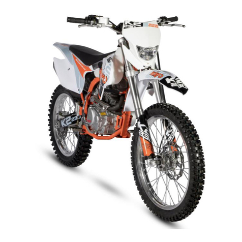
KAYO MOTOR KT250 User manual

ZHEJIANG KAYO MOTOR CO., LTD.
www.kayomoto.com
- 1 -
KAYO MOTO
KT250
USER’S MANUAL
WWW.KAYOMOTO.COM

ZHEJIANG KAYO MOTOR CO., LTD.
www.kayomoto.com
- 2 -
This service manual is edited by KAYO
No part of this publication may be reproduced without authorization.
ZHEJIANG KAYO MOTOR CO., LTD reserves the right to make changes at any time without
notice and without incurring any obligation.
The vehicle pictured in this owner’s manual may not match your actual vehicle.

ZHEJIANG KAYO MOTOR CO., LTD.
www.kayomoto.com
- 3 -
PREFACE
Congratulations on your purchase of the KT250 Dirt Bike, and we believe that this choice won’t let
you down.
This manual will give you an understanding of the better use of our product. It has specialized the
maintenance and adjustment procedures, disassembly and assembly points, inspection and repair
points, troubleshooting methods and maintenance technical data, in addition, there is a detailed
graphic information to guide the operation.
Please read this manual carefully and carry out maintenance according to the standard operation
techniques, which can effectively prolong the service life of each component, improve the engine
performance and the reliability of the vehicle.
For the sake of technical development, KAYO will reserve the right of modifying motorcycle
structure, equipment, and spare parts without notice. Due to that different markets have different
law’s requirement, we’ve adjusted model accordingly, the model image in this manual maybe not
match your actual vehicle. In addition, if there is any question concerning this manual, please visit
our website www.kayomoto.com and consult our customer service.
The contents of this manual are subject to change without prior notice due to vehicle
improvement. The actual state of the motorcycle shall prevail during maintenance.
ZHEJIANG KAYO MOTOR CO., LTD.
ENGINEERING OFFICE
MARCH. 2021

ZHEJIANG KAYO MOTOR CO., LTD.
www.kayomoto.com
- 4 -
CONTENT
MEANINGS OF REPRESENTATION ……………………………………………………………….8
SYMBOLS USED…………………………….………………………………………………….8
DEGREES OF RISK AND SYMBOLS .........…………………………………………………...8
ADVICE………….……………………………………………………………………………………9
APPEARANCE …………………………………...…………………………………………………10
KT250 COMPONENTS AND POSITIONS………………………….…………………………10
VIN CODE AND ENGINE NUMBER………………………………………………………...……12
VIN CODE………………………………………………………...…………….…12
ENGINE NUMBER………………………………………………………………….…...……12
PARAMETER……………………………………………………………………………………….13
DIMENSION AND QUALITY PARAMETER………………………………………………13
CONTROLS……………………………………………………………………….…………………15
CLUTCH LEVER………………………………………………………………………………15
FRONT DISC BRAKE………….……………………………………………………………15
THROTTLE LEVER…………………………………………………………………………16
STARTING……………………………………………………………………………………16
STOPPING……………………………………………………………………………………16
FUEL TANK SWITCH…………………………………………………………………………17
SHIFTING………………………………………………………………………………………17
REAR DISC BRAKE………………………………...…………………………………………18
PARKING SUPPORT……….……………….…………………………………………………18
HOUR COUNTER……………………………………...………………………………………19
PREPAREING FOR USE …………………………...………………………………………………20
ADVICE ON FIRST USE………………………………………………………………………20
RUNNING-IN PROCESS………………………………………………………………………20
RIDING INSTRUCTIONS………………………………………………….………………………21
PREPARATION BEFORE RIDING……………………………………………………………21
PRECAUTIONS FOR STARTING.……………………………………………………………21
PREACUSTIONS STOPPING…………………………………………………………………21
PREACUTIONS FOR TURNING...……………………………………………………………22
PRECAUTIONS FOR ACCELERATION……………………………………………………22
PRECAUTIONS FOR SHIFTING……………………………………………………………22
PRECAUTIONS FOR BRAKING……………………………………………………………22
PRECAUTIONS FOR STOPPING & PARKING…………………………………………22
SUGGESTED INSPECTION TIME FOR ALL PARTS OF THE VEHICLE……………………….23
SUSPENSION SYSTEM……………………………………………………………………………24
CHECK THE COMPRESSION AND REBOUND OF THE VEHICLE INCLUDING THE
DRIVER……………………………………………………….…….………………………24
ADJUSTING THE LOW-SPEED COMPRESSION DAMPING OF THE REAR SHOCK
ABSORBER…………………………………………………….…….………...……………….24
ADJUSTING THE HIGH-SPEED COMPRESSION DAMPING OF THE REAR SHOCK
ABSORBER……………………………………………….…….………...…………………….24

ZHEJIANG KAYO MOTOR CO., LTD.
www.kayomoto.com
- 5 -
ADJUSTING THE REBOUND DAMPING OF THE REAR SHOCK ABSORBER………….25
MEASURE THE DISTANCE BETWEEN THE CENTER OF THE REAR WHEEL AND THE
REAR FENDER IN SUSPENSION…………………….…….………...………………………25
MEASURE DISTANCE BETWEEN CENTER OF REAR WHEEL AND REAR FENDER
UNDER NO LOAD…………………….…….………...……………………………………….25
MEASURE DISTANCE BETWEEN REAR WHEEL CENTER AND REAR FENDER IN
DRIVING CONDITION…………………….…….………...………………………………….26
ADJUSTING THE SPRING PRELOAD OF REAR SHOCK ABSORBER…………………...26
CHECK FOR THE SETTING OF FRONT SHOCK ABSORBER…………….…….………....26
ADJUSTING THE COMPRESSION DAMPING OF FRONT SHOCK ABSORBER………...27
ADJUSTING THE REBOUND DAMPING OF FRONT SHOCK ABSORBER……………....27
ADJUSTING THE HANDLEBAR…………………….…….………...……………………….27
VEHICLE MAINTENANCE……… ……………………………………………………………….28
PLACEMENT…………………………………………………………………………………28
REMOVING OR INSTALLING THE DISC BRAKE COVER……………………………….28
REMOVING OR INSTALLING THE FRONT SHOCK ABSORBER GUARD PLATE…….28
REMOVING OR INSTALLING THE FRONT DISC BRAKE.………………………………29
REMOVING OR INSTALLING THE FRONT SHOCK ABSORBER………………………29
REMOVING OR INSTALLING THE LINKAGE……….……………………………………29
CHECK THE FRONT STEERING……… ………………….…………………………………30
LUBRICATION AND INSTALLATION OF STEERING HEAD BEARING....……………...30
REMOVING OR INSTALLING FRONT HEADLIGHT…………….………………………...31
REMOVING OR INSTALLING THE FRONT FENDER……………………………….…......31
REMOVING OR INSTALLING THE REAR SHOCK ABSORBER………………….….........32
REMOVING OR INSTALLING THE SEAT CUSHION………………………………………32
REMOVING OR INSTALLING THE AIR FILTER HOUSING……………………………….33
REMOVING OR INSTALLING THE AIR FILTER……………………………………………33
CLEANING AND MAINTENANCE OF AIR FILTER………………………………………...34
REMOVING OR INSTALLING THE EXHAUST PIPE…………….…………………………34
REMOVING OR INSTALLING THE MUFFLER TUBE………….………………………….35
REMOVING OR INSTALLING THE FUEL TANK………….……………………………….35
CHECK AND CLEAN THE CHAIN…………...……………………………………….……...36
REMOVING OR INSTALLING THE CHAIN……...………………………………………….36
CHECK AND ADJUST THE CHAIN TENSION...…………………………………………….37
CHECK THE STRUCTURE OF THE REAR SPROCKET, ENGINE SPROCKET AND GUIDE
CHAIN...………………………………………………………………………………………...38
CHECK THE FRAME………………………………………………………………………….38
CHECK THE FORK…………………………………………………………………………….38
CHECK THE THROTTLE CABLE…………………………………………………………….38
CHECK THE STEERING HANDLE…………………………………………………………...39
ADJUST THE CLUTCH LEVER………………………………………………………….........39
CHECK AND MAINTENANCE THE BRAKE SYSTEM………………………………................40
CHECK THE FREE-PLAY OF FRONT BRAKE LEVER…………………………..................40
CHECK THE CABLE OF FRONT BRAKE LEVER…………………………..........................40

ZHEJIANG KAYO MOTOR CO., LTD.
www.kayomoto.com
- 6 -
CHECK THE DISC BRAKE…………………………................................................................41
REFUEL THE FRONT BRAKE LIQUID LEVEL…..................................................................41
CHECK THE FRONT BRAKE PADS….....................................................................................41
CHECK THE FREE-PLAY OF FOOT BRAKE….......................................................................42
CHECK THE REAR BRAKE DISK LIQUID LEVEL................................................................43
REFUEL THE REAR BRAKE DISK LIQUID LEVEL..............................................................43
CHECK THE REAR BRAKE PADS............................................................................................44
TIRE INSPECTION AND MAINTENANCE.....................................................................................45
REMOVING OR INSTALLING THE FRONT WHEEL.............................................................45
REMOVING OR INSTALLING THE REAR WHEEL...............................................................45
TIRE INSPECTION......................................................................................................................45
CHECK TIRE PRESSURE...........................................................................................................46
CHECK SPOKE............................................................................................................................46
ELECTRICAL SYSTEM.....................................................................................................................47
REMOVING OR INSTALLING THE BATTERY.......................................................................47
CHANGING THE BATTERY.......................................................................................................47
MAIN CABLE
KT250 VEHICLE WIRING DIAGRAM......................................................................................48
COOLING SYSTEM...........................................................................................................................49
COOLING SYSTEM PROFILE...................................................................................................49
REMOVING OR INSTALLING THE COWLING AND HOSE.................................................49
CHECK ANTIFREEZE LEVEL...................................................................................................50
DRAIN OUT THE COOLANT.....................................................................................................50
FILLING THE COOLING SYSTEM...........................................................................................51
INTRODUCING ABOUT THE ENGINE STRUCTURE ...........................................................52
INSTALLING THE ENGINE.......................................................................................................52
ENGINE MAINTENANCE AND ADJUSTMENT......................................................................52
CHECK THE VALVE CLEARANCE..........................................................................................52
COMPRESSION PRESSURE CHECK........................................................................................53
ADJUSTMENT OF CLUTCH CONTROL SYSTEM.................................................................53
THE ENGINE ADJUSTMENT...........................................................................................................54
IDLE SPEED ADJUSTMENT OF CARBURETOR...................................................................54
CLEAN THE CARBURETOR.....................................................................................................54
CHECK THE SHIFT LEVER POSITION....................................................................................55
ADJUST THE SHIFT LEVER POSITION..................................................................................55
INSPECTION OR REPLACEMENT OF SPARK PLUGS..........................................................55
ENGINE LUCRICATION SYSTEM...................................................................................................56
LUBRICANT SELECTION……………………………………………….................................56
LUBRICANT INSPECTION………………………………………............................................56
LUBRICANT REPLACEMENT……………………………………………..............................57
REMOVAL AND INSTALLATION OF OIL PUMP....................................................................57
OIL PUMP INSPECTION………………………….……………………………………….….58
COMMON PROBLEMS AND CAUSES OF LUBRICATION SYSTEM……………………58
ENGINE TIGHTENING TORQUE TABLE………………………………………………………59

ZHEJIANG KAYO MOTOR CO., LTD.
www.kayomoto.com
- 7 -
TROUBLESHOOTING.......................................................................................................................60
SELECTION AND RATIO OF ENGINE OIL....................................................................................63
MOTORCYCLE CLEANING.............................................................................................................64
STORAGE............................................................................................................................................65
PREPARING FOR LONG STORAGE.........................................................................................65
PREPARING FOR USE AFTER LONG STORAGE...................................................................65
MAINTENANCE POINTS..................................................................................................................66
TIGHTENING TORQUE TABLE FOR THE WHOLE VEHICLE....................................................71

ZHEJIANG KAYO MOTOR CO., LTD.
www.kayomoto.com
- 8 -
MEANINGS OF REPRESENTATION
SYMBOLS USED
The meaning of specific symbols is described below
* All work marked with this symbol requires specialist knowledge and technical understanding. If
you do not have the confidence to perform that, you can go to an authorized KAYO workshop or
KAYO after-sale service point. There, your motorcycle will be optimally cared for by specially
trained experts using the specialist tools required.
→ Indicates a page reference (more information is provided on the specified page).
DEGREES OF RISKAND SYMBOLS
Your safety, and the safety of others, is very important. Operating this motorcycle safety is an
important responsibility. Please read this manual carefully.
Safety Messages preceded by a safety alert symbol and one of three signal words:
DANGER: Indicates a danger that will immediately and invariably lead to fatal or permanent injury
if the appropriate measures are not taken.
Warning: Indicates a danger that is likely to lead to fatal or serious injury if the appropriate measures
are not taken.
CAUTION: Indicates a danger that may lead to minor injuries if the appropriate measures are not
taken.
Other important information:
Please note that it is not practical or possible to warn you about all hazards associated with operating
or maintaining a motorcycle.
Therefore, you must have basic mechanical safety knowledge and use your own good judgement.
If you cannot complete the process of operating or maintaining, please consult a more experienced
senior technician before operation.

ZHEJIANG KAYO MOTOR CO., LTD.
www.kayomoto.com
- 9 -
ADVICE
Most of off-road motorcycle fatalities are caused by head injuries. Without helmets, the chances of
serious injury or death caused by head injuries are much higher. So always wear an approved
motorcycle helmet and protective apparel such as goggles, gloves and boots while riding, which will
save your life at the critical moment.
Initially, this series of vehicles were designed for off-road racing, without considering the problem of
carrying passengers, and what’s more, there is no backseat, handlebar and pedal for carrying people.
So please be sure not to use this motorcycle to carry any other people except the driver, which may
easily lead to a safety accident.
Do not use non-original parts to modify the car, and do not arbitrarily remove the original
components from the vehicle. If you need to replace any parts, please use spare parts and accessory
products that are approved and/or recommended by KAYO and have them installed by an authorized
KAYO workshop. KAYO accepts no liability for any personal modification, other products and any
resulting damage or loss.
Our KT series products are specially designed for off-road and woodland crossing, so they are not
suitable for highway or long-distance riding.
If you insist on using them in that way, the tires may be overused due to high speed rotation and
shorten its service life.
It is also not suitable for urban use, as long waiting time at traffic lights may cause the engine to
overheat and shorten its service life.
Please take care of your vehicle and avoid any problem caused by improper use.
Please check your motorcycle carefully before riding and do the maintenance accordingly after use.
When the motorcycle fell, check the main parts first. It would lead to a accident easily and endanger
your own safety when riding a faulty vehicle.
When using this motorcycle, the temperature of the engine and exhaust pipe is very high, so it needs
to a period to cool down after parking. During this period, do not touch or move the engine or
exhaust pipe to avoid scald.
Do not wear shorts while riding, otherwise leg injuries may happen.

ZHEJIANG KAYO MOTOR CO., LTD.
www.kayomoto.com
- 10 -
APPEARANCE
KT250 COMPONENTS AND POSITIONS
1 2 3 4 5 6 7 8
9 10 11 12 13 14 15 16 17 18
No.
Name
No.
Name
1
Front fender
10
Front brake caliper
2
Headlight
11
Front shock
3
Handlebar
12
Fuel tank
4
Vent pipe
13
Carburetor
5
Fuel tank cap
14
Gear shift lever
6
Fuel tank petcock
15
Pedal
7
Air filter cover
16
Chain
8
Chain guide cover
17
Chain guide
9
Front disc brake cover
18
Rear sprocket

ZHEJIANG KAYO MOTOR CO., LTD.
www.kayomoto.com
- 11 -
19 20 21 22 23 24 25 26
27 28 29 30 31 32 33 34 35
No.
Name
No.
Name
19
Taillight
28
Rear brake caliper
20
Rear fender
29
Aluminum swingarm
21
Exhaust pipe muffler
30
Triangle rocker arm
22
Seat
31
U-shape rocker arm
23
Rear shock
32
Rear brake oil cup
24
Upper clamp
33
Brake pedal
25
Cooling water tank
34
Exhaust pipe
26
Lower clamp
35
Front disc brake
27
Rear disc brake

ZHEJIANG KAYO MOTOR CO., LTD.
www.kayomoto.com
- 12 -
ENGINE NUMBER
The engine number of KT250 is located on the engine
box behind the cylinder block.
VIN CODE
Vin code of KT250 is located on the head pipe and
Name Plate.

ZHEJIANG KAYO MOTOR CO., LTD.
www.kayomoto.com
- 13 -
PARAMETER
DIMENSIONS AND QUALITY PARAMETER - KT250
L*W*H(mm)
2180×820×1254
Wheelbase(mm)
1488
Net weight(kg)
110
Tire size
F: 80/100-21;R: 110/100-18
Seat height(mm)
955
Min ground clearance
(mm)
344
Tank volume(L)
7.5
Engine Parameters
Engine type
Single cylinder, two stroke, water cooling, vertical
Clutch type
Wet type, Multiple disk
Cylinder
diameter×stroke
66.8×64mm
Oil
TORCO GP-7 total synthesis
Displacement
224cc
Max. Power(kw/r/min)
29/8500
Max. Torque(NM/r/min)
36/7500
Compression Ratio
6.5:1
Shift type
Usually engaged two - stage transmission six - speed transmission,
International profile 1-N-2-3-4-5-6
Starting
Electric
Fuel control system
PWK competitive carburetor
Battery
Lithium battery for high performance electric starting, very light in
weight
Chain
#520, 12T/51T
Frame/Shock/Brake/Wheel system Parameters
Frame type
Central double cradle type high-strength steel tube frame, KAYO
International patent design
Front shock
Inverted dual adjustable front shock, L=950mm, 300mm stroke
Rear shock
Compression recovery dual adjustable nitrogen airbag rear shock,
L=480mm, 110mm stroke, CRF general configuration
Swingarm
High strength aluminum alloy internal high-pressure forming structure,
improved progressive rate of forged aluminum connecting rod system

ZHEJIANG KAYO MOTOR CO., LTD.
www.kayomoto.com
- 14 -
Handlebar
Competitive high-strength aluminum alloy fat bar (imported),,material
7075 Φ28.6mm, with Kayo special ultra-soft off-road grip
F/R rims
F 1.60×21, R 2.15×18, 7050 high strength aluminum rim ,
forged CNC wheel hub
F brake system
Double piston pump hydraulic brake system, Ø240mm, CNC ergonomic
small handle bar
R brake system
Single piston pump hydraulic brake system, Ø240mm, forged internal
brake pedal
Others
Air filter type
Sponge filter core filter type
Fuel type
92# and above grade gasoline
Motorcyclists
1 person(rider)
Maximum load mass
120kg

ZHEJIANG KAYO MOTOR CO., LTD.
www.kayomoto.com
- 15 -
CONTROL
CLUTCH
clutch lever
The clutch is controlled by the clutch lever, which is
fitted on the left side of the handlebar and functioned
by pinching the lever with your left hand.
By adjusting the screw, you can change the distance
between the clutch lever and handlebar as you wish.
This adjustment will not either change the structure or
affect the normal use.
FRONT DISC BRAKE
hand brake lever
front brake calipers
The front disc brake is controlled by the hand brake
lever, which is fitted on the right side of the handlebar
and functioned by the pinching the lever with your
right hand.
By adjusting the screw, you can change the distance of
the brake lever and handlebar as you wish. This
adjustment will not either change the structure or affect
the normal use.
The front wheel adopts the floating-caliper disc brake,
which is installed under the left front shock and fixed
by two bolts.

ZHEJIANG KAYO MOTOR CO., LTD.
www.kayomoto.com
- 16 -
THROTTLE LEVER
throttle lever
The throttle lever is located on the right side of the
handlebar and is controlled by turning with the right
hand.
Turn the handle counterclockwise to increasing the
engine. It will back to normal smoothly once you lease
the handle.
STARTING
start button
The start button is a square gray one and fitted on the
right side of the handlebars, near the throttle grip.
It needs long press on the button when starting.
Attention:When starting, you should pinch the brake
with your left hand to prevent sudden starting when the
transmission is I gear.
ATTENTION:There should have fuel in the fuel tank
before starting the engine, and the fuel tank switch
should be in the open position.
STOPPING
stopping button
The stopping button is square red one and fitted on the
left side of the handlebar near the grip.
It needs long press on the button when stopping.

ZHEJIANG KAYO MOTOR CO., LTD.
www.kayomoto.com
- 17 -
FUELTANK SWITCH
fuel tank switch
The fuel tank switch is located on the bottom left side
of the fuel tank. By turning the switch, you can control
the entrance of the fuel into into the carburetor, so as to
achieve the control purpose.
The meaning of symbols on the oil tank switch is
shown as the left picture.
“ON”: indicates that the switch is opened for oil
discharge.
“OFF”: indicates that the switch is closed, and the
oil discharge is stopped.
“RES”: indicates that the reserve oil is activated.
CAUTION: Reserve oil is only used in emergency
situations, so it needs to be replenished in time when
the fuel is insufficient.
SHIFTING
gearshift
The gearshift is located on the left side of the engine,
which is functioned by stepping on and hooking on the
shift lever.

ZHEJIANG KAYO MOTOR CO., LTD.
www.kayomoto.com
- 18 -
The KT250 engine has six gear as International
Standard, and you can find the illustration on the left.
REAR DISC BRAKE
foot brake pedal
The foot brake pedal is located on the right side of the
engine and is functioned by stepping.
Note:In actual use, the brake operation should be
mainly through foot brake, use hand brake as a
supplement.
rear brake caliper
The rear brake adopts a floating clamp disc brake,
which one is located on the right side of the rear wheel
and fixed by a disc brake bracket.
PARKING SUPPORT

ZHEJIANG KAYO MOTOR CO., LTD.
www.kayomoto.com
- 19 -
The KT250 uses a single side stand for parking.
It is located on the left side of the vehicle.
When in use, the vehicle is centered, and the single
support is kicked to expand it, and the entire vehicle is
tilted to the left to make the single support contact the
ground and support the motorcycle.
HOUR COUNTER
The KT250 hour meter is located on the main beam
tube at the front end of the fuel tank of the frame.

ZHEJIANG KAYO MOTOR CO., LTD.
www.kayomoto.com
- 20 -
PREPARING FOR USE
ADVICE ON FIRST USE
1. Before your first trip, read the entire operating instructions carefully, especially the section of
“Controls” and “Riding Instructions”.
2. When driving, please carry out a standardized run-in first.
3. If any parts problems are found during using, you can repair that according to this manual or
contact KAYO Dealers for professional aid.
4. After each use, clean the vehicle with running water.
5. Do not drive in inclement weather (e.g. rainstorm, blizzard, etc.) unless necessary.
6. KAYO is not responsible for any vehicle problems caused by malicious acts.
RUN-IN PROCESS
Motorcycle engines have a lot of relative moving parts, such as pistons, piston rings, cylinder
blocks, meshing transmission gears, etc. Therefore, in the initial stage of use, the engine must be
standardized. The running-in can make the moving parts adapt to each other, correct the working
gap, and form a good smooth friction surface that can withstand larger loads. Only after standard
running-in can the engine have excellent performance and reliability.
The recommended running-in steps are as follows:
1. 0-2.5h stage: Using under the throttle level of 50% ~ 75%, the speed should be changed
frequently to avoid the motorcycle working at the same condition for a long time,
Let the engine rest and cool down for 5 ~ 10 minutes after each 1-hour work.
Do not accelerate suddenly to protect your throttle.
2. 2.5-4h stage: Using under the throttle level of 50% ~ 75% throttle and work for a long time at
the same condition.
In actual working, the throttle can be up to full level, but not more than 5 ~ 10 seconds;
3. 4-5h stage: Using under the throttle level of 75% ~ 100%
4. More than 5h: increase the speed to 60 ~ 80km/h, until the engine performance can be fully
played.
DANGER:When riding a motorcycle, please do not speed up regardless of the consequences, this
behavior is easy to cause engine damage and causing safety accidents therewith.
So, please ride the vehicle properly.
Table of contents
Other KAYO MOTOR Motorcycle manuals

KAYO MOTOR
KAYO MOTOR K6-R User manual

KAYO MOTOR
KAYO MOTOR KMB60 2021 User manual

KAYO MOTOR
KAYO MOTOR TS90 User manual

KAYO MOTOR
KAYO MOTOR T2 User manual

KAYO MOTOR
KAYO MOTOR T4 User manual

KAYO MOTOR
KAYO MOTOR TT 125 User manual

KAYO MOTOR
KAYO MOTOR K4 User manual

KAYO MOTOR
KAYO MOTOR K2 User manual

KAYO MOTOR
KAYO MOTOR TD125 User manual