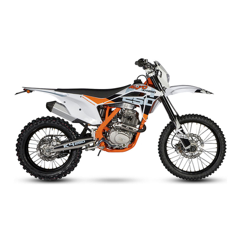
KAYO MOTOR TT 125 User manual

KAYO MOTO
TT 125
SERVICE MANUAL
www.kayomoto.com

This service manual is edited by KAYO.
Please do not modify the content without authorization.
Manufacturer has the right to improve and update the model’s structure and spare parts without notice.
The model in the image may be different from the real model.
PREFACE
Thank you for choosing the 21 TD125 of KAYO MOTO as your choice for off-road recreation. I believe you will
not be disappointed with this choice.
This manual is designed to help you better use our products. This manual describes in detail the maintenance and
adjustment procedures, disassembly and assembly essentials, inspection and maintenance points, troubleshooting
methods and maintenance technical data of TD125, with detailed graphic data to guide the operation.
Please read this manual carefully and carry out maintenance according to the standard operation techniques, which
can effectively prolong the service life of each component, improve the engine performance and the reliability of

the vehicle.
For the sake of technological development, KAYO reserves the right to modify the construction, equipment and
parts of the motorcycle without prior notice. Due to the different regulations and requirements in different markets,
we have made appropriate adjustments to the models, so the images in the manual may be different from the
standard motorcycle. In addition, if you have any questions, please go to our official website
www.kayomoto.com and contact our service staff. We must accept with humility.
The contents of this manual are subject to change without prior notice due to vehicle improvement. The actual state
of the vehicle shall prevail during maintenance.
ZHEJIANG KAYO MOTOR CO., LTD.
ENGINEERING OFFICE
AUGUST. 2021

Content
Meaning of Symbols and Technical Terms 6
Suggestions for Daily Use 7
Parts and Position 8
21 TT 125 Parts and Position 8
Steel chassis 9
VIN and Engine Number 10
VIN Number 10
Engine Number 10
Specification 11
Manipulation 12
Front disc brake 12
Throttle 12
Ignition 13
Stall 13
Fuel tank switch 13
Gear Shifting 14
Rear disc brake 14
Parking stand 15
Notes before use 16
Suggestions for first-time users 16
Running-in process 16
Riding guide 17
Checking items before riding 17
Notes when ignition 17
Notes when starting 17
Notes when cornering 18
Notes when acceleration 18
Notes when gear shifting 18
Notes when braking 18
Notes when parking 18
Maintenance Periodic Table 19
Suspension system setup 20
Check the compression and rebound of the motorcycle when riding 20
Measure distance from center of rear wheel to rear fender in suspension 20
Measure distance from center of rear wheel to rear fender under no load 20
Measure distance from center of rear wheel to rear fender in riding condition 21
Adjust the spring preload of the rear shock 22
Check the setup of the front shock 22
Adjust handlebar 22
Maintenance 23
Placement of motorcycle 23
Disassembly and assembly of front shock protector 23
Disassembly and assembly of front disc brake 23
Disassembly and assembly of front shock 24
Disassembly and assembly of clamp 24
Check the head steering 24
Lubrication and installation of steering head bearing 25
Disassembly and assembly of front fender 25
Disassembly and assembly of rear shock 26
Disassembly and assembly of seat 26
Disassembly and assembly of air filter 26
Cleaning and maintenance of air filters 26
Disassembly and assembly of exhaust pipe 27
Disassembly and assembly of muffler 27
Disassembly and assembly of fuel tank 28
Check the chain and clean 28

Disassembly and assembly of the chain 28
Check and adjust the chain tension 28
Inspect rear sprocket, engine sprocket and chain guide structure 29
Inspection of the frame 30
Inspection of the swing arm 30
Inspection of the throttle cable 30
Inspection of the handle bar 30
Check and maintain the brake system 31
Check the free stroke of the front brake handle 31
Inspection of the disc brake 31
Check the fluid level of front brake disc 32
Refill the front brake disc fluid oil 32
Inspection of the disc brake 32
Check the free movement of the foot brake 33
Check the rear disc brake fluid level 33
Refill rear disc brake fluid 34
Tire inspection and maintenance 35
Removal and installation of front wheel 35
Removal and installation of rear wheel 35
Check the outside surface of the tire 35
Check tire pressure 36
Check the wheel spokes 36
Engine installation 37
Engine maintenance and adjustment 37
Inspection of bolts and nuts of cylinder and cylinder body 37
Check valve clearance 37
Inspection of compression pressure 38
Adjustment of clutch control system 38
Adjustment around the engine 39
Idle speed adjustment of carburetor 39
Clean the carburetor 39
Check shift lever position 40
Adjust the position of the shift lever 40
Check and replace spark plug 41
Lubrication system of engines 42
Selection of lubrication oil 42
Lubricating oil inspection 42
Lubricating oil replacement 42
Engine repair 43
Cylinder and valves 43
Main parameters and maintenance standards of cylinder parts 44
Fault symptom and cause analysis 44
Removal of left cover of cylinder head 45
Timing check 45
Removal of valve cover 46
Check valve clearance 46
Removal of cylinder head 46
Disassembly of cylinder head 47
Inspection of valves and valve springs 48
Inspection of rocker arm and rocker arm shaft 48
Inspection of camshaft components 49
Inspection of cylinder head 49
Check and grind valve seats 49
Inspection of valve guide 50
Replacement of valve guide 50
Measure width of valve seat contact area 50
Assembly of cylinder head 51
Installation of cylinder head 52

Cylinder block and piston 53
Main parameters and maintenance standards of cylinder block and piston 53
Fault symptom and cause analysis 54
Inspection of cylinder block 55
Removal of piston and piston ring 56
Inspection of piston and piston ring 56
Installation of piston ring 57
Installation of piston 57
Installation of cylinder block 58
Clutch, driving gear, driven gear, oil pump, shifting mechanism 58
Main parameters and maintenance standards 59
Fault symptom and cause analysis 59
Removal of right trim cover 60
Adjustment of clutch stroke 60
Removal of right crankcase cover 60
Clutch disassembly 61
Disassembly of driving and driven gears 61
Removal of engine oil pump 61
Disassemble shift mechanism 62
Inspection of right crankcase cover 62
Inspection of driving and driven tooth 63
Check the oil pump 63
Check shift mechanism 64
Assembly of shift mechanism 64
Assembly of oil pump 64
Assembly of driving and driven teeth 65
Clutch assembly 65
Installation of clutch 66
Assembly of right crankcase cover 66
Assembly of right crankcase cover 67
Right trim cover for installation 67
Magneto, timing chain 67
Removal of left rear cover 68
Removal of left front cover 68
Removal of magneto stator 68
Removal of magneto rotor 69
Removal of starting motor and starting sprocket 69
Removal of transition plate 70
Removal of timing chain 70
Removal of tensioning arm, tensioning rod and tensioning roller 70
Inspection of left front cover and left back cover 70
Transition plate, starting motor, starting sprocket inspection 71
Magneto stator, rotor inspection 71
Installation of tensioning arm, tensioning rod and tensioning roller 72
Transition plate installation 72
Installation of starting motor and starting sprocket 73
Installation of magneto stator 73
Installation of magneto rotor 74
Installation of left cover 74
Crankcase, crankshaft, main and auxiliary shafts and speed drum 74
Main parameters and maintenance standards 75
Fault symptom and cause analysis 75
Decomposition of crankcase 75
Disassembly of crankshaft, main and auxiliary shaft 76
Decomposition of variable speed drum 76
Inspection of crankshaft 76
Left and right crankshaft box bearing inspection 77
Check shift fork, fork shaft and shift drum 77
Check the combination of main and auxiliary shafts 78
Inspection of starting shaft 78
Assembly of variable speed drum 78
Installation of variable speed drum, main and auxiliary shaft, crankshaft and starting shaft 79
Installation of crankcase 79
Engine troubleshooting 81
Motorcycle cleaning 84
Storage of motorcycles 85
The preparation of the motorcycle before long unused 85
The main points of maintenance 86
Vehicle tightening torque meter 91
Meaning of Symbols and Technical Terms
The symbol "*" indicates that the operation requires professional knowledge and technical understanding of the
operator. If you do not have confidence to complete this operation, you can go to a professional maintenance shop
or KAYO after-sale service, to operate by professionals.
The symbol "→" indicates that the specific information is on the following page number.
DANGER/WARNING/CAUTION
In this manual, the words "DANGER/WARNING/CAUTION" will appear. Please read their following words
carefully to protect yourself and your vehicle. The meanings of "DANGER", "WARNING" and "CAUTION" are
as follows:
DANGER: Be alert to a high level of danger
WARNING: Be vigilant to moderate risk
CAUTION: Be alert to minor danger
Please note that in this manual, we only enumerate the main safety issues related to vehicle maintenance and repair,
so the contents of warning symbols cannot cover all the potential dangers during the use and repair of the vehicle.

Therefore, in addition to the related matters that "DANGER", "WARNING" and "CAUTION" indicate, users must
also have a basic knowledge of mechanical safety. If you are not sure to complete the entire maintenance and repair
operation, please consult a more experienced senior technician before operation.
Suggestions for Daily Use
The vast majority of off-road motorcycle fatalities are caused by head injuries. Without helmets, the chances of
serious injury or death from a head-hit will be much higher. Therefore, we strongly recommend that you wear a full
set of safety equipment such as helmet, goggles, gloves and boots when driving, which will save your life at the
critical moment.
The purpose of this series of models at the beginning of the design is off-road racing, without considering the
purpose of carrying passengers, and this bike does not have a rear seat, handles and pedals for carrying people, so
please be sure not to use this bike to carry other people except the driver, this behavior can easily lead to safety
accidents.
Try to avoid using non-original parts to modify the bike, and do not arbitrarily delete the original parts of the bike,
if you need to replace the parts of the bike, please choose the original parts produced by KAYO or parts from
authorized manufacturers by KAYO. In addition, KAYO is not responsible for any vehicle problems caused by
personal modification and the use of unauthorized parts.
Please check your motorcycle carefully before each use and maintain it according to the maintenance manual after
use. After the vehicle falls, please first check whether the main parts are damaged, because driving a motorcycle
with a fault is very easy to lead to the occurrence of accidents, endanger riders’ own safety.
When in use, the temperature of the engine and exhaust pipe is very high, so it will take some time to cool down
after parking. During this period, please do not touch or move the engine and exhaust pipe to avoid burns.

Parts and Position
21 TT 125 Parts and Position
1 2 3 4 5 6 7
8 9 10 11 12 13 14 15 16 17 18
No.
Name
No.
Name
1
Front fender
10
Front fork
2
Headlight
11
Fuel tank
3
Handlebar
12
Carburetor
4
Vent pipe
13
Gear shift lever
5
Fuel tank cap
14
Pedal
6
Fuel tank petcock
15
Side stand
7
Chain slider
16
Chain
8
Front brake disc
17
Chain guide
9
Front brake caliper
18
Rear sprocket
19 20 21 22 23 24

25 26 27 28 29 30 31
No.
Name
No.
Name
19
Rear fender
26
Rear brake caliper
20
Muffler
27
Swing arm
21
Seat
28
Rear brake oil cup
22
Rear shock
29
Brake pedal
23
Upper clamp
30
Steel chassis
24
Lower clamp
31
Muffler pipe
25
Rear brake disc
VIN and Engine Number
VIN Number

VIN Number of 21 TT 125 is carved on the frame of head pipe.
Engine Number
Engine Number of 21 TT125 is carved on the engine crankcase
body behind gear lever.
Specification
TT125 size and quality parameters
Length*Width*Height
(mm)
1780×750×1120
Wheelbase (mm)
1220
Weight (kg)
72
Tyre size
Front 70/100-17; Rear90/100-14
Seat height (mm)
855
Ground clearance (mm)
290
Fuel tank capacity (L)
5.5

Engine parameter
Engine type
Single cylinder, four stroke, air - cooled, manual clutch
Displacement
119.6cc
Max power (kw/r/min)
5.6/8000
Max torque (N•m/r/min)
8.5/5000
Compression ratio
9.3:1
Gear shift type
Constant mesh 4 speed gears
Start method
Kick
Ignition system
CDI
Chain
#428;15T/41T
Frame/shock/Braking/Wheel parameters
Frame type
Steel pipe suspension frame,Kayo patent
Front shock absorber
Inverted front shock nonadjustable absorber, L=735mm
Rear shock absorber
Normal rear shock nonadjustable absorber, L=360mm
Rear swing arm
Steel swing arm
Handlebar
Steel handlebar
Front&rear rim
Front: 1.60×17, Rear: 1.85×14; steel rim
Front brake system
Hydraulic brake system, brake discΦ210mm
Rear brake system
Hydraulic brake system, brake discΦ200mm
Other
Air filter
Sponge filter
Manipulation
Front disc brake
Hand brake handle
The front disc brake is controlled by the hand brake handle,
which is located at the right end of the handlebar and operated
by the pinching of the handle by the right hand.
The front wheel brake adopts the floating clamp disc brake,
which is installed at the lower end of the left front shock and
fixed by 2 bolts.

Front brake caliper
Throttle
Throttle
The throttle is located on the right side of the handlebar and is
controlled by right hand rotation. Turn the throttle up when
turning the handle counterclockwise, then turn the handle back
to the position after releasing the handle.
Ignition
Starting lever
The vehicle starting lever is located on the right side of the
engine, and the motorcycle engine can be started by stepping on
the starting lever.
Note:The brake should be pinched when starting to prevent the
engine from starting with the gear.
Note: there should be fuel in the fuel tank before starting the
engine, and the fuel tank switch should be in the open position.
Stall
Stall switch
The stall switch of the engine is located on the left side of the
handlebar near the handle cover. It is a round red button. Long
press it to turn off the engine and make it stall.
Fuel tank switch
The fuel tank switch is located on the bottom left side of the
tank. By rotating the switch, you can control the fuel to flow

Fuel tank switch
into the carburetor, so as to achieve control effect.
Gear Shifting
Gearshift lever
The shift lever is located on the left side of the engine, which is
operated by stepping on and lifting the shift lever. The 21
TT125 engines are in four-gear gear with constant meshing.
Rear disc brake
Foot brake pedal
The foot brake pedal is located on the right side of the engine
and is operated by stepping.
Note: when brake, the foot brake should be the main brake,
hand brake as a supplement.
Rear brake caliper
The rear brake adopts a floating clamp disc brake, whose clamp
body is located on the right side of the rear wheel and is fixed
by a disc brake bracket.
Parking stand

The 21 TT125 uses a single stand for parking. The single stand
is on the left side of the motorcycle. When in use, straighten the
motorcycle, kick the single stand to expand it, and tilt the
motorcycle to the left so that the single stand touches the
ground and supports the motorcycle.
Notes before use
Suggestions for first-time users
1.Please read this manual before driving, especially sections "complete vehicle handling" and "riding
instructions".
2.Please perform Normative running-in before riding.
3.If any parts problems are found in use, please refer to this manual for repair or contact the dealer.
4.After each use, the motorcycle needs to be cleaned with water.
5.Do not drive in inclement weather (e.g. rainstorm, blizzard, etc.) unless necessary.
6.The company is not responsible for any vehicle problems caused by malicious acts.
Running-in process
Motorcycle engines have many parts that make relative movements, such as pistons, piston rings, cylinder blocks,
and meshing transmission gears. Therefore, in the initial stage of use, the engine must be regularly run-in. The
running-in can adapt the moving parts to each other, correct the working gap, and form a good smooth friction
surface that can withstand large loads. Only after the running-in engine is standardized can it have excellent
performance and reliability.
The recommended running-in steps are as follows:
1. 0 ~ 2.5h stage: when using a motorcycle at 50% ~ 75% throttle, the speed should be changed frequently to

avoid the motorcycle running at the same throttle for a long time; after each hour of work, let the engine cool for 5
~ 10 minutes; Avoid rapid acceleration, and the throttle cannot be either too large nor too small.
2. 2.5 ~ 4h stage: work under 50% ~ 75% throttle, at this time, the motorcycle can run at the same throttle for a
long time. During the work, the throttle can reach 100%, but the duration is not higher than 5-10 seconds;
3.4 ~ 5h stage: Use motorcycles at 75% ~ 100% throttle.
4. Above 5h: Increase the speed to 60 ~ 80km / h, knowing that the engine performance can be fully exerted.
DANGER: When driving a motorcycle, please do not accelerate at all costs. This behavior can easily lead to
engine damage and safety accidents. Therefore, please pay attention to certain driving skills when using a
motorcycle.
Riding guide
Checking items before riding
1.Check the fuel level in the tank
2.Check the oil level in the oil cup of hand brake
3.Check the oil level in the oil cup of foot brake
4.Check the foot brake clamp pad
5.Check the hand brake clamp pad
6.Check braking effect of braking system
7.Check the chain
8.Check rear sprocket, engine sprocket and chain guide
9.Check the chain adjuster
10.Check the surface of tires
11.Check tire pressure
12.Check the battery power
13.Check the thickness of the front disc brake
14.Check the thickness of the rear disc brake
15.Check the torque of each fastener
16.Check the engine gear
17.Check the cover
18.Check the fuel tank switch
19.Check protective gear if it is fully worn

Notes when ignition
Kick starting steps are as follows:
1.Turn the oil tank switch to the "ON" position;
2.Pinch the brake handle with the right hand;
3.Step the right foot on the starting lever vigorously;
4.The engine starts and process ends.
Notes when starting
1.Before starting, inspection should be carried out first, including the state of the vehicle and the driver's clothing.
2.When starting the vehicle speed should not be too fast.
3.For safety, please start in gear 1.
Notes when cornering
1.Slow down in advance when cornering.
2.When cornering, lower center of gravity to reduce side-way.
3.When cornering, do not shift gears.
Notes when acceleration
1.Do not accelerate on the corners.
2.After acceleration, shift gears in time.
Notes when gear shifting
1.Do not increase the throttle while shifting gears
2.Do not shift gears on the corners.
Notes when braking
1.When braking, the foot brake should be the main; hand brake as a supplement.
2.The level of the brake fluid in the brake fluid cup should be checked frequently.
3.When the brake fluid is insufficient, appropriate brake fluid should be added according to the maintenance
manual in time.
Notes when parking
1.When parking, slow down first and then stop.Do not brake in a sudden
2.When parking, expand the side stand and tilt the motorcycle to the left for parking.
3.Please put the gear in neutral before stopping.
Maintenance Periodic Table
Every 30 hours
Every 20 hours
Every 10 hours/after racing
Once after 1 hour riding

Check and charge the battery
●
●
●
Check the front disc brake pads
●
●
●
Check the rear disc brake pads
●
●
●
Check the front and rear disc brakes
●
●
●
Check the brake hose for damage or leaks
●
●
●
Check the rear disc brake fluid level
●
●
●
Checking the free stroke of the brake pedal
●
●
●
Checking the frame
●
●
●
Check shock top
●
●
●
Check shock connecting rod
●
●
●
Check the surface of the tires
○
●
●
●
Check tire pressure
○
●
●
●
Check if the rim bearing is loose
●
●
●
Check the rim
●
●
●
Check for rim edge runout
○
●
●
●
Check spoke tension
○
●
●
●
Check the chain, rear sprocket, engine sprocket, chain guide and chain cover
●
●
●
Check chain tension
○
●
●
●
Oil all moving parts (such as chains, handles, etc.) and check for smooth operation
●
●
●
Check the front disc brake fluid level
●
●
●
Checking the free stroke of the hand brake lever
●
●
●
Check if the steering head bearing is loose
○
●
●
●
Check valve clearance
○
●
Check clutch
●
Change the gear oil
○
●
●
●
Check all hoses (such as fuel, exhaust, etc.) and bushings for cracks, leaks, and incorrect wiring
○
●
●
●
Check cables for damage and sharp bends
●
●
●
Clean the air cleaner and air cleaner case
●
●
●
Check if the screws and nuts are tight
○
●
●
●
Replace the air filter
●
Check the carburetor idle speed
○
●
●
●

Final inspection: check if the vehicle is running safely and test run
○
●
●
●
○One time interval
●Periodic interval
Note: This table is for reference only. Please adjust the specific cycle according to the use of the motorcycle.
Warning: For inspection, adjustment and replacement of engine parts, please consult Kayo
Suspension system setup
Check the compression and rebound of the motorcycle when riding
To ensure the best riding characteristics and avoid damage to
the awing arm, shocks, rocker arms and frame, the basic setting
of the suspension components must match the rider's weight.
The standard weight of rider for 21 TD125 off-road
motorcycles is shown in the table below.
21 TT125
30~50kg
If the rider's weight is above or below the standard range, the
basic setting of these sections must be adjusted accordingly.
Measure distance from center of rear wheel to rear fender in suspension
The measurement procedure is as follows:
1.Set up the whole motorcycle, so that the rear wheel is
completely suspended.
2.Select a fixed point on the side of the rear mud-guard and
mark it as "Point 1".
3.Measure the distance from "Point 1" to the center of the rear
axle and record it as "A1".
4.Lower the motorcycle from the rack
Measure distance from center of rear wheel to rear fender under no load
The measurement procedure is as follows:
1.Righten the motorcycle so that the center of the tire is
perpendicular to the ground.
2.Measure the distance from the center of the rear axle of the
motorcycle to "Point 1" and record it as "A2".
3.Use side stand to support the whole motorcycle
4.Calculate the difference between "A1" and "A2" and denote it
as "D1".

The D1 value of 21 TT125 is shown as follows,
D1
TT125
10~40mm
Measure distance from center of rear wheel to rear fender in riding condition
The measurement procedure is as follows:
1.The rider rides the motorcycle (engine does not start)
2.Righten the motorcycle so that the center of the tire is
perpendicular to the ground.
3.Measure the distance from the center of the rear axle of the
motorcycle to "point 1" and record it as "A3".
4.The rider uses side stand to support the motorcycle and leave
the seat cushion.
Calculate the difference between "A1" and "A2" and denote it
as "D2".
The D2 value of 21 TT125 is shown as follows,
D2
TT125
55~110mm
If "D2" measured by the customer is lower than the factory
value, the spring preload can be lowered appropriately; If
measured "D2" is higher than the factory value, the spring
preload can be adjusted higher; If "D2" is far less than the
factory value, it is necessary to replace the spring with a lower
hardness; If "D2" is much greater than the factory value, it is
necessary to replace the spring with a greater hardness.
Adjust the spring preload of the rear shock
Table of contents
Other KAYO MOTOR Motorcycle manuals

KAYO MOTOR
KAYO MOTOR T4 User manual

KAYO MOTOR
KAYO MOTOR K6-R User manual

KAYO MOTOR
KAYO MOTOR KMB60 2021 User manual

KAYO MOTOR
KAYO MOTOR KT250 User manual

KAYO MOTOR
KAYO MOTOR TD125 User manual

KAYO MOTOR
KAYO MOTOR K2 User manual

KAYO MOTOR
KAYO MOTOR T2 User manual

KAYO MOTOR
KAYO MOTOR K4 User manual

KAYO MOTOR
KAYO MOTOR TS90 User manual